battery capacity Hyundai Ioniq Electric 2017 Owner's Manual
[x] Cancel search | Manufacturer: HYUNDAI, Model Year: 2017, Model line: Ioniq Electric, Model: Hyundai Ioniq Electric 2017Pages: 582, PDF Size: 37.73 MB
Page 12 of 582
H5
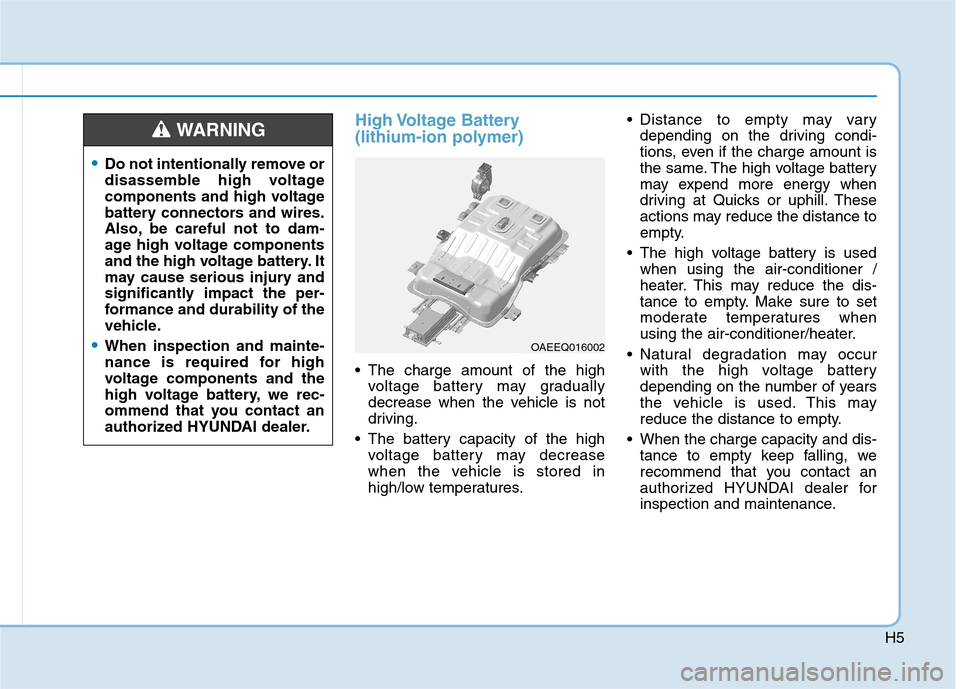
High Voltage Battery
(lithium-ion polymer)
The charge amount of the highvoltage battery may gradually
decrease when the vehicle is not
driving.
The battery capacity of the high voltage battery may decrease
when the vehicle is stored in
high/low temperatures. Distance to empty may vary
depending on the driving condi-
tions, even if the charge amount is
the same. The high voltage battery
may expend more energy when
driving at Quicks or uphill. These
actions may reduce the distance to
empty.
The high voltage battery is used when using the air-conditioner /
heater. This may reduce the dis-
tance to empty. Make sure to set
moderate temperatures when
using the air-conditioner/heater.
Natural degradation may occur with the high voltage battery
depending on the number of years
the vehicle is used. This may
reduce the distance to empty.
When the charge capacity and dis- tance to empty keep falling, we
recommend that you contact an
authorized HYUNDAI dealer for
inspection and maintenance.
•Do not intentionally remove or
disassemble high voltage
components and high voltage
battery connectors and wires.
Also, be careful not to dam-
age high voltage components
and the high voltage battery. It
may cause serious injury and
significantly impact the per-
formance and durability of the
vehicle.
When inspection and mainte-
nance is required for high
voltage components and the
high voltage battery, we rec-
ommend that you contact an
authorized HYUNDAI dealer.
WARNING
OAEEQ016002
Page 290 of 582
3-121
Convenient features of your vehicle
3
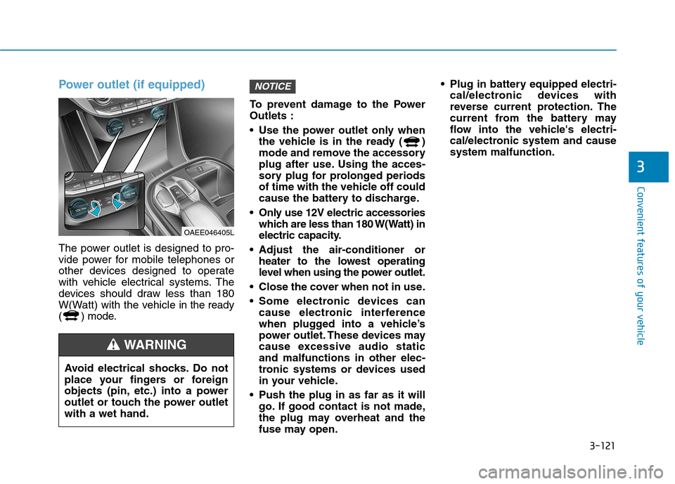
Power outlet (if equipped)
The power outlet is designed to pro-
vide power for mobile telephones or
other devices designed to operate
with vehicle electrical systems. The
devices should draw less than 180
W(Watt) with the vehicle in the ready
( ) mode. To prevent damage to the PowerOutlets :
Use the power outlet only when
the vehicle is in the ready ( )
mode and remove the accessory
plug after use. Using the acces-
sory plug for prolonged periods
of time with the vehicle off could
cause the battery to discharge.
Only use 12V electric accessories which are less than 180 W(Watt) in
electric capacity.
Adjust the air-conditioner or heater to the lowest operating
level when using the power outlet.
Close the cover when not in use.
Some electronic devices can cause electronic interference
when plugged into a vehicle’s
power outlet. These devices may
cause excessive audio staticand malfunctions in other elec-
tronic systems or devices used
in your vehicle.
Push the plug in as far as it will go. If good contact is not made,
the plug may overheat and the
fuse may open. Plug in battery equipped electri-
cal/electronic devices with
reverse current protection. The
current from the battery may
flow into the vehicle's electri-
cal/electronic system and causesystem malfunction.
NOTICE
OAEE046405L
Avoid electrical shocks. Do not
place your fingers or foreign
objects (pin, etc.) into a power
outlet or touch the power outletwith a wet hand.
WARNING
Page 467 of 582
7
Maintenance
7
Maintenance
Motor compartment...............................................7-3
Maintenance services ...........................................7-4Owner's responsibility ......................................................7-4
Owner maintenance precautions ..................................7-4
Owner maintenance ...............................................7-5 Owner maintenance schedule ........................................7-5
Scheduled maintenance services.........................7-7 Normal maintenance schedule - For Europe.............7-8
Maintenance under severe usage conditions -
For Europe ........................................................................7-10 Normal maintenance schedule - Except Europe ....7-12
Maintenance under severe usage conditions -
Except Europe..................................................................7-14
Explanation of scheduled maintenance items .7-16 Coolant...................................................................7-17 Checking the coolant level ...........................................7-17 Changing coolant.............................................................7-20
Brake fluid ............................................................7-21 Checking the brake fluid level .....................................7-21
Washer fluid .........................................................7-22 Checking the washer fluid level ..................................7-22
Climate control air filter .....................................7-23 Filter inspection ...............................................................7-23 Wiper blades .........................................................7-25
Blade inspection ..............................................................7-25
Blade replacement ..........................................................7-25
Battery (12 Volt) ..................................................7-27 For best battery service................................................7-28
Battery capacity label ....................................................7-28
Battery recharging .........................................................7-29
Reset features .................................................................7-30
Tires and wheels ..................................................7-31 Tire care ............................................................................7-31
Recommended cold tire inflation pressures.............7-32
Check tire inflation pressure........................................7-33
Tire rotation .....................................................................7-34
Wheel alignment and tire balance ..............................7-35
Tire replacement ............................................................7-35
Wheel replacement .........................................................7-36
Tire traction ....................................................................7-36
Tire maintenance ............................................................7-36
Tire sidewall labeling ......................................................7-36
Low aspect ratio tires ....................................................7-40
Fuses ......................................................................7-42 Instrument panel fuse replacement ...........................7-43
Motor compartment panel fuse replacement ..........7-44
Fuse/relay panel description .......................................7-45
7
Page 494 of 582
7-28
Maintenance
When you do not use the vehiclefor a long time in a low tempera-
ture area, disconnect the battery
and keep it indoors.
Always charge the battery fully to prevent battery case damage
in low temperature areas.
For best battery service
Keep the battery securely mounted.
Keep the battery top clean and dry.
Keep the terminals and connec-tions clean, tight, and coated with
petroleum jelly or terminal grease.
Rinse any spilled acid from the bat- tery immediately with a solution of
water and baking soda.
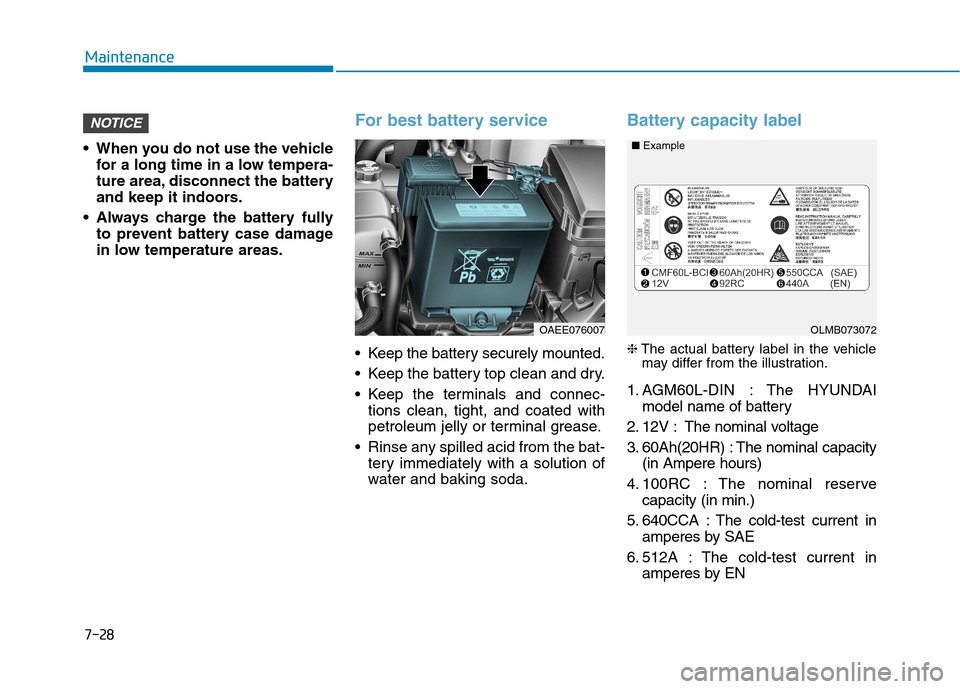
Battery capacity label
❈ The actual battery label in the vehicle
may differ from the illustration.
1. AGM60L-DIN : The HYUNDAI model name of battery
2. 12V : The nominal voltage
3. 60Ah(20HR) : The nominal capacity (in Ampere hours)
4. 100RC : The nominal reserve capacity (in min.)
5. 640CCA : The cold-test current in amperes by SAE
6. 512A : The cold-test current in amperes by EN
NOTICE
OAEE076007OLMB073072
■
Example
Page 508 of 582
7-42
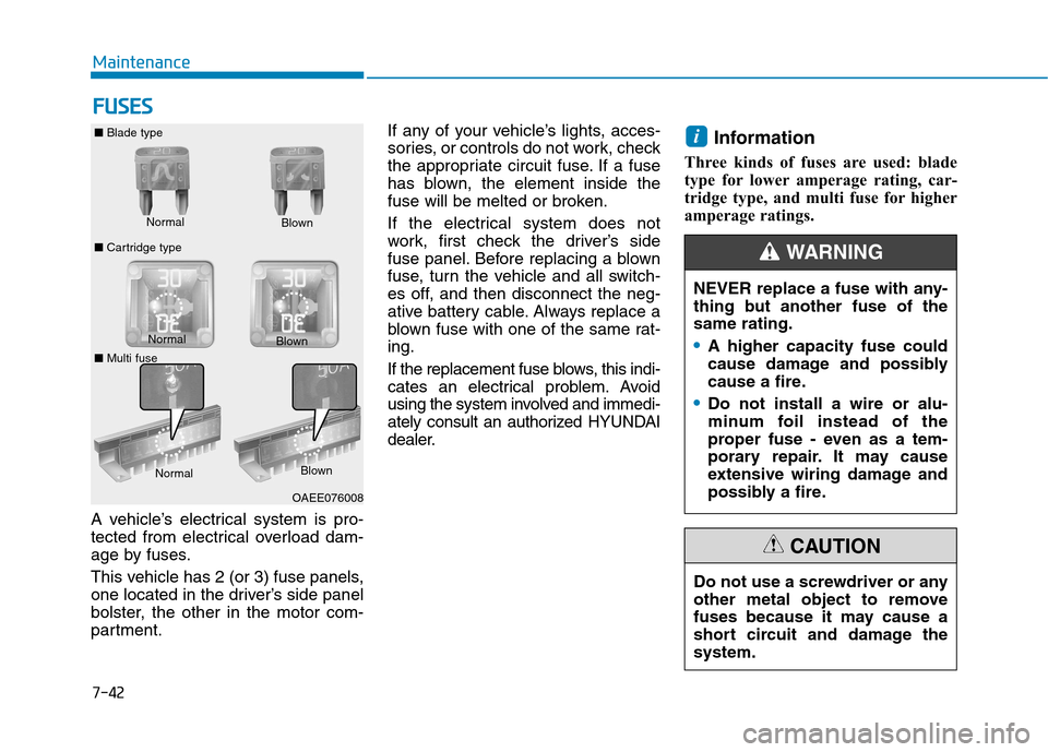
MaintenanceF
F UU SSEE SS
A vehicle’s electrical system is pro-
tected from electrical overload dam-
age by fuses.
This vehicle has 2 (or 3) fuse panels,
one located in the driver’s side panel
bolster, the other in the motor com-
partment. If any of your vehicle’s lights, acces-
sories, or controls do not work, check
the appropriate circuit fuse. If a fuse
has blown, the element inside the
fuse will be melted or broken.
If the electrical system does not
work, first check the driver’s side
fuse panel. Before replacing a blown
fuse, turn the vehicle and all switch-
es off, and then disconnect the neg-
ative battery cable. Always replace a
blown fuse with one of the same rat-ing.
If the replacement fuse blows, this indi-
cates an electrical problem. Avoid
using the system involved and immedi-
ately consult an authorized HYUNDAI
dealer.
Information
Three kinds of fuses are used: blade
type for lower amperage rating, car-
tridge type, and multi fuse for higher
amperage ratings.
i
Normal
■
Blade type
■ Cartridge type Blown
Normal Blown
OAEE076008
Do not use a screwdriver or any
other metal object to remove
fuses because it may cause a
short circuit and damage thesystem.
CAUTION
NEVER replace a fuse with any-
thing but another fuse of thesame rating.
A higher capacity fuse could
cause damage and possibly
cause a fire.
Do not install a wire or alu-
minum foil instead of the
proper fuse - even as a tem-
porary repair. It may cause
extensive wiring damage and
possibly a fire.
WARNING
NormalBlown
■ Multi fuse
Page 511 of 582
7-45
7
Maintenance
4. Check the removed fuse; replace itif it is blown. To remove or insert
the fuse, use the fuse puller in the
motor compartment fuse panel.
5. Push in a new fuse of the same rating, and make sure it fits tightly
in the clips. If it fits loosely, consult
an authorized HYUNDAI dealer.
After checking the fuse panel in
the motor compartment, securely
install the fuse panel cover. You
may hear a clicking sound if the
cover is securely latched. If it is
not securely latched, electrical
failure may occur from water con-tact.Multi fuse
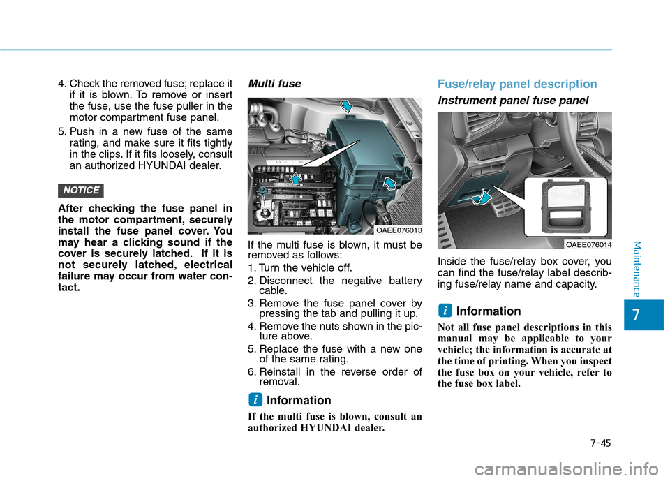
If the multi fuse is blown, it must be
removed as follows:
1. Turn the vehicle off.
2. Disconnect the negative battery cable.
3. Remove the fuse panel cover by pressing the tab and pulling it up.
4. Remove the nuts shown in the pic- ture above.
5. Replace the fuse with a new one of the same rating.
6. Reinstall in the reverse order of removal.
Information
If the multi fuse is blown, consult an
authorized HYUNDAI dealer.
Fuse/relay panel description
Instrument panel fuse panel
Inside the fuse/relay box cover, you
can find the fuse/relay label describ-
ing fuse/relay name and capacity.
Information
Not all fuse panel descriptions in this
manual may be applicable to your
vehicle; the information is accurate at
the time of printing. When you inspect
the fuse box on your vehicle, refer to
the fuse box label.
i
i
NOTICE
OAEE076013
OAEE076014
Page 522 of 582
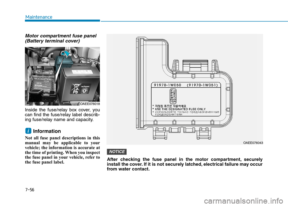
Motor compartment fuse panel(Battery terminal cover)
Inside the fuse/relay box cover, you
can find the fuse/relay label describ-
ing fuse/relay name and capacity.
Information
Not all fuse panel descriptions in this
manual may be applicable to your
vehicle; the information is accurate at
the time of printing. When you inspect
the fuse panel in your vehicle, refer to
the fuse panel label.
i
7-56
Maintenance
OAEE076018
OAEE076043
After checking the fuse panel in the motor compartment, securely
install the cover. If it is not securely latched, electrical failure may occur
from water contact.
NOTICE
Page 545 of 582
8-2
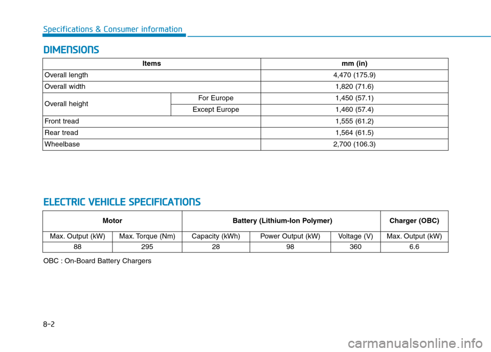
Specifications & Consumer informationD
D IIMM EENN SSIIOO NNSS
E
E LLEE CCTT RR IICC VV EEHH IICC LLEE SS PP EECCIIFF IICC AA TTIIOO NNSS
Motor Battery (Lithium-Ion Polymer)Charger (OBC)
Max. Output (kW)
Max. Torque (Nm) Capacity (kWh)Power Output (kW)Voltage (V)Max. Output (kW)
88
295 28983606.6
Itemsmm (in)
Overall length4,470 (175.9)
Overall width1,820 (71.6)
Overall heightFor Europe1,450 (57.1)
Except Europe1,460 (57.4)
Front tread1,555 (61.2)
Rear tread 1,564 (61.5)
Wheelbase2,700 (106.3)
OBC : On-Board Battery Chargers