break Hyundai Kona EV 2019 Owner's Manual
[x] Cancel search | Manufacturer: HYUNDAI, Model Year: 2019, Model line: Kona EV, Model: Hyundai Kona EV 2019Pages: 540, PDF Size: 21.84 MB
Page 56 of 540
2-41
Safety system of your vehicle
2
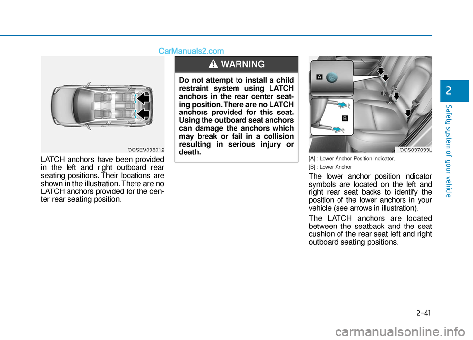
LATCH anchors have been provided
in the left and right outboard rear
seating positions. Their locations are
shown in the illustration. There are no
LATCH anchors provided for the cen-
ter rear seating position.[A] : Lower Anchor Position Indicator,
[B] : Lower Anchor
The lower anchor position indicator
symbols are located on the left and
right rear seat backs to identify the
position of the lower anchors in your
vehicle (see arrows in illustration).
The LATCH anchors are located
between the seatback and the seat
cushion of the rear seat left and right
outboard seating positions.
Do not attempt to install a child
restraint system using LATCH
anchors in the rear center seat-
ing position. There are no LATCH
anchors provided for this seat.
Using the outboard seat anchors
can damage the anchors which
may break or fail in a collision
resulting in serious injury or
death.
WARNING
OOSEV038012OOS037033L
Page 57 of 540
2-42
Safety system of your vehicle
Securing a child restraint withthe LATCH anchors system
To install a LATCH-compatible child
restraint in either of the rear outboard
seating positions:
1. Move the seat belt buckle away from
the lower anchors.
2. Move any other objects away from the anchors that could prevent a
secure connection between the child
restraint and the lower anchors.
3. Place the child restraint on the vehi- cle seat, then attach the seat to the
lower anchors according to the
instructions provided by the child
restraint manufacturer.
4. Follow the child restraint instructions for properly adjusting and tightening
the lower attachments on the child
restraint to the lower anchors. The recommended weight for the
LATCH system is under 65 lb (30
kg).
How to determine an appropriate
child restraint weight:
Child weight + Child restraint
weight < 65 lb (30kg)
NOTICE
Take the following precautions
when using the LATCH system:
Read and follow all installation
instructions provided with
your child restraint system.
To prevent the child from
reaching and taking hold of
unretracted seat belts, buckle
all unused rear seat belts and
retract the seat belt webbing
behind the child. Children can
be strangled if a shoulder belt
becomes wrapped around
their neck and the seat belt
tightens.
NEVER attach more than one
child restraint to a single
anchor. This could cause the
anchor or attachment to come
loose or break.
Always have the LATCH sys-
tem inspected by your author-
ized HYUNDAI dealer after an
accident. An accident can
damage the LATCH system
and may not properly secure
the child restraint.
WARNING
Page 58 of 540
2-43
Safety system of your vehicle
2
Securing a child restraint seatwith "Tether Anchor" system
First secure the child restraint with
the LATCH lower anchors or the seat
belt. If the child restraint manufactur-
er recommends that the top tether
strap be attached, attach and tighten
the top tether strap to the top tether
strap anchor.
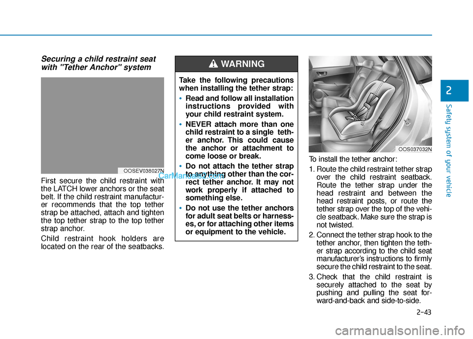
Child restraint hook holders are
located on the rear of the seatbacks. To install the tether anchor:
1. Route the child restraint tether strap
over the child restraint seatback.
Route the tether strap under the
head restraint and between the
head restraint posts, or route the
tether strap over the top of the vehi-
cle seatback. Make sure the strap is
not twisted.
2. Connect the tether strap hook to the tether anchor, then tighten the teth-
er strap according to the child seat
manufacturer’s instructions to firmly
secure the child restraint to the seat.
3. Check that the child restraint is securely attached to the seat by
pushing and pulling the seat for-
ward-and-back and side-to-side.
Take the following precautions
when installing the tether strap:
Read and follow all installation
instructions provided with
your child restraint system.
NEVER attach more than one
child restraint to a single teth-
er anchor. This could cause
the anchor or attachment to
come loose or break.
Do not attach the tether strap
to anything other than the cor-
rect tether anchor. It may not
work properly if attached to
something else.
Do not use the tether anchors
for adult seat belts or harness-
es, or for attaching other items
or equipment to the vehicle.
WARNING
OOS037032N
OOSEV038027N
Page 67 of 540
2-52
Safety system of your vehicle
They are designed to help protect the
heads of the front seat occupants
and the rear outboard seat occupants
in certain side impact collisions.
The curtain air bags are designed to
deploy during certain side impact
collisions, depending on the crash
severity.
The side and curtain air bags on
both sides of the vehicle may deploy
if a rollover or possible rollover is
detected.
The curtain air bags are not designed
to deploy in all side impact or rollover
situations.
How Does the Air Bag System
Operate?
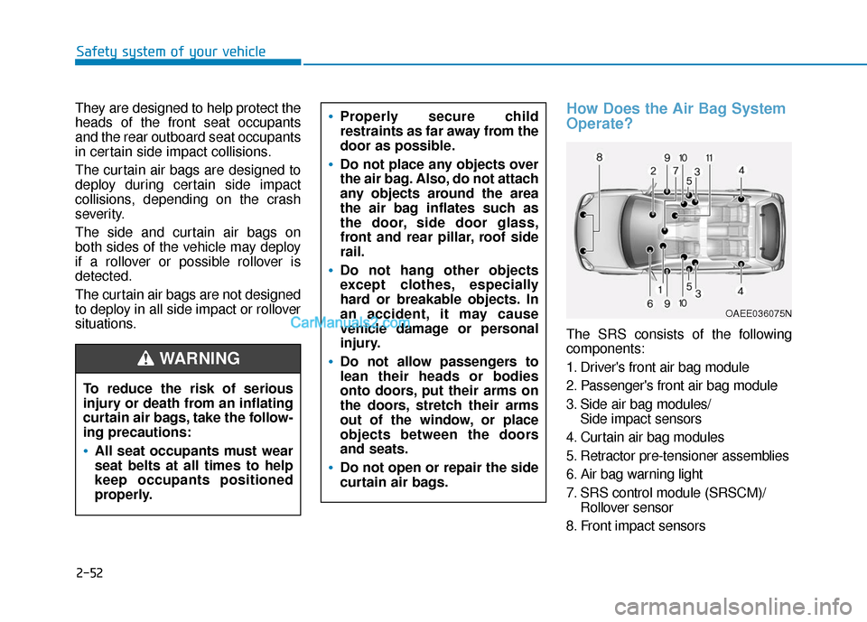
The SRS consists of the following
components:
1. Driver's front air bag module
2. Passenger's front air bag module
3. Side air bag modules/ Side impact sensors
4. Curtain air bag modules
5. Retractor pre-tensioner assemblies
6. Air bag warning light
7. SRS control module (SRSCM)/ Rollover sensor
8. Front impact sensors
To reduce the risk of serious
injury or death from an inflating
curtain air bags, take the follow-
ing precautions:
All seat occupants must wear
seat belts at all times to help
keep occupants positioned
properly.
Properly secure child
restraints as far away from the
door as possible.
Do not place any objects over
the air bag. Also, do not attach
any objects around the area
the air bag inflates such as
the door, side door glass,
front and rear pillar, roof side
rail.
Do not hang other objects
except clothes, especially
hard or breakable objects. In
an accident, it may cause
vehicle damage or personal
injury.
Do not allow passengers to
lean their heads or bodies
onto doors, put their arms on
the doors, stretch their arms
out of the window, or place
objects between the doors
and seats.
Do not open or repair the side
curtain air bags.
WARNING
OAEE036075N
Page 227 of 540
3-143
Convenient features of your vehicle
3
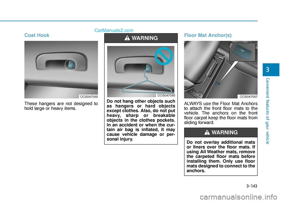
Coat Hook
These hangers are not designed to
hold large or heavy items.
Floor Mat Anchor(s)
ALWAYS use the Floor Mat Anchors
to attach the front floor mats to the
vehicle. The anchors on the front
floor carpet keep the floor mats from
sliding forward.
Do not hang other objects such
as hangers or hard objects
except clothes. Also, do not put
heavy, sharp or breakable
objects in the clothes pockets.
In an accident or when the cur-
tain air bag is inflated, it may
cause vehicle damage or per-
sonal injury.
WARNING
OOS047066
Do not overlay additional mats
or liners over the floor mats. If
using All Weather mats, remove
the carpeted floor mats before
installing them. Only use floor
mats designed to connect to the
anchors.
WARNING
OOS047065OOS047067
Page 317 of 540
5-84
Driving your vehicle
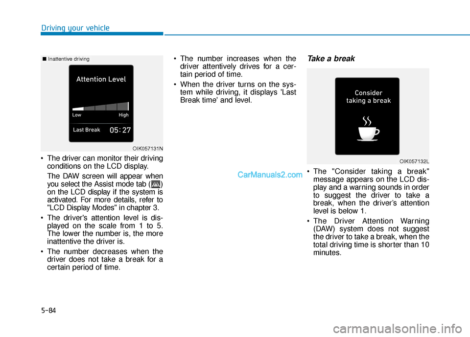
The driver can monitor their driving conditions on the LCD display.
The DAW screen will appear when
you select the Assist mode tab ( )
on the LCD display if the system is
activated. For more details, refer to
"LCD Display Modes" in chapter 3.
The driver's attention level is dis- played on the scale from 1 to 5.
The lower the number is, the more
inattentive the driver is.
The number decreases when the driver does not take a break for a
certain period of time. The number increases when the
driver attentively drives for a cer-
tain period of time.
When the driver turns on the sys- tem while driving, it displays 'Last
Break time' and level.
Take a break
The "Consider taking a break"message appears on the LCD dis-
play and a warning sounds in order
to suggest the driver to take a
break, when the driver’s attention
level is below 1.
The Driver Attention Warning (DAW) system does not suggest
the driver to take a break, when the
total driving time is shorter than 10
minutes.
OIK057131N
OIK057132L
■ Inattentive driving
Page 318 of 540
5-85
Driving your vehicle
5
Resetting the System
The last break time is set to 00:00and the driver's attention level is
set to 5 (very attentive) when the
driver resets the Driver Attention
Warning (DAW) system.
The Driver Attention Warning (DAW) system resets in the follow-
ing situations.
- The vehicle is turned OFF.
- The driver unfastens the seat beltand then opens the driver's door.
- The vehicle is stopped for more than 10 minutes.
The Driver Attention Warning (DAW) system operates again,
when the driver restarts driving.
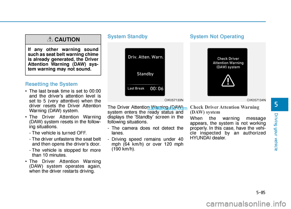
System Standby
The Driver Attention Warning (DAW)
system enters the ready status and
displays the 'Standby' screen in the
following situations.
- The camera does not detect thelanes.
- Driving speed remains under 40 mph (64 km/h) or over 120 mph
(190 km/h).
System Not Operating
Check Driver Attention Warning
(DAW) system
When the warning message
appears, the system is not working
properly. In this case, have the vehi-
cle inspected by an authorized
HYUNDAI dealer.
OIK057133NOIK057134N
If any other warning sound
such as seat belt warning chime
is already generated, the Driver
Attention Warning (DAW) sys-
tem warning may not sound.
CAUTION
Page 319 of 540
5-86
Driving your vehicleThe Driver Attention Warning sys-
tem utilizes the camera sensor on
the front windshield for its opera-
tion. To keep the camera sensor in
the best condition, you should
observe the followings:
Do not disassemble the cameratemporarily to tint the window or
to attach any types of coatings
and accessories. If you disas-
semble a camera and assemble
it again, take your vehicle to an
authorized HYUNDAI dealer and
have the system checked for cal-
ibration.
NEVER locate any reflective objects (i.e. white paper, mirror)
over the dashboard. Any light
reflection may cause a malfunc-
tion of the Driver Attention Alert
(DAW) system.
Pay extreme caution to keep the camera sensor out of water.
NEVER arbitrarily disassemble the camera assembly, nor apply
any impact on the camera
assembly.
NOTICE
The Driver Attention Warning
(DAW) system is not a substi-
tute for safe driving practices,
but a convenience function
only. It is the responsibility of
the driver to always drive cau-
tiously to prevent unexpected
and sudden situations from
occurring. Pay attention to the
road conditions at all times.
The system may suggest a
break according to the dri-
ver's driving pattern or habits
even if the driver doesn't feel
fatigue.
The driver, who feels fatigued,
should take a break, even
though there is no break sug-
gestion by the Driver Attention
Warning (DAW) system.
WARNING
The Driver Attention Warning
(DAW) system may not properly
operate with limited alerting in
the following situations:
The lane detection perform-
ance is limited. (For more infor-
mation, refer to "Lane Keeping
Assist (LKA) system" in this
chapter.)
The vehicle is driven erratical-
ly or is abruptly turned for
obstacle avoidance (e.g. con-
struction area, other vehicles,
fallen objects, bumpy road).
Forward drivability of the vehi-
cle is severely undermined
(possibly due to wide variation
in tire pressures, uneven tire
wear-out, toe-in/toe-out align-
ment).
The vehicle drives on a curvy
road.
The vehicle drives on a bumpy
road.
CAUTION
Page 353 of 540
5-120
Driving your vehicle
Vehicle capacity weight
860 lbs. (390 kg)
Vehicle capacity weight is the maxi-
mum combined weight of occupants
and cargo. If your vehicle is equipped
with a trailer, the combined weight
includes the tongue load.
Seating capacity
Total : 5 persons (Front seat : 2 persons,
Rear seat : 3 persons)
Seating capacity is the maximum
number of occupants including a
driver, your vehicle may carry.
However, the seating capacity may
be reduced based upon the weight of
all of the occupants, and the weight
of the cargo being carried or towed.
Do not overload the vehicle as there
is a limit to the total weight, or load
limit including occupants and cargo,
the vehicle can carry.
Towing capacity
We do not recommend using this
vehicle for trailer towing.
Cargo capacity
The cargo capacity of your vehicle
will increase or decrease depending
on the weight and the number of
occupants and the tongue load, if
your vehicle is equipped with a trailer.
Steps for determining correct load limit
1. Locate the statement "The com-
bined weight of occupants and
cargo should never exceed XXX
kg or XXX lbs." on your vehicle's
placard.
2. Determine the combined weight of the driver and passengers that will
be riding in your vehicle.
3. Subtract the combined weight of the driver and passengers from
XXX kg or XXX lbs.
4. The resulting figure equals the available amount of cargo and lug-
gage load capacity. For example, if
the "XXX" amount equals 1400
lbs. and there will be five 150 lb
passengers in your vehicle, the
amount of available cargo and lug-
gage load capacity is 650 lbs.
(1400 - 750 (5 x 150) = 650 lbs.) 5. Determine the combined weight of
luggage and cargo being loaded
on the vehicle. That weight may
not safely exceed the available
cargo and luggage load capacity
calculated in Step 4.
6. If your vehicle will be towing a trail- er, load from your trailer will be
transferred to your vehicle. Consult
this manual to determine how this
reduces the available cargo and
luggage load capacity of your vehi-
cle.
Do not overload the vehicle as
there is a limit to the total
weight, or load limit, including
occupants and cargo, the vehi-
cle can carry. Overloading can
shorten the life of the vehicle. If
the GVWR or the GAWR is
exceeded, parts on the vehicle
can break, and it can change the
handling of your vehicle. These
could cause you to lose control
and result in an accident.
WARNING
Page 417 of 540
7-37
7
Maintenance
Maximum Inflation Pressure
The maximum air pressure to which
a cold tire may be inflated. The max-
imum air pressure is molded onto the
sidewall.
Maximum Load Rating
The load rating for a tire at the maxi-
mum permissible inflation pressure
for that tire.
Maximum Loaded VehicleWeight
The sum of curb weight; accessory
weight; vehicle capacity weight; and
production options weight.
Normal Occupant Weight
The number of occupants a vehicle
is designed to seat multiplied by 150
pounds (68 kg).
Occupant Distribution
Designated seating positions.
Outward Facing Sidewall
An asymmetrical tire has a particular
side that faces outward when mount-
ed on a vehicle. The outward facing
sidewall bears white lettering or
bears manufacturer, brand, and/or
model name molding that is higher or
deeper than the same moldings on
the inner facing sidewall.
Passenger (P-Metric) tire
A tire used on passenger cars and
some light duty trucks and multipur-
pose vehicles.
Ply
A layer of rubber-coated parallel
cords.
Pneumatic tire
A mechanical device made of rubber,
chemicals, fabric and steel or other
materials, that, when mounted on an
automotive wheel provides the trac-
tion and contains the gas or fluid that
sustains the load.
Pneumatic options weight
The combined weight of installed
regular production options weighing
over 5 lb. (2.3 kg) in excess of the
standard items which they replace,
not previously considered in curb
weight or accessory weight, includ-
ing heavy duty breaks, ride levelers,
roof rack, heavy duty battery, and
special trim.
Recommended InflationPressure
Vehicle manufacturer's recommend-
ed tire inflation pressure as shown
on the tire placard.