charger Hyundai Kona EV 2019 Owner's Manual
[x] Cancel search | Manufacturer: HYUNDAI, Model Year: 2019, Model line: Kona EV, Model: Hyundai Kona EV 2019Pages: 540, PDF Size: 21.84 MB
Page 76 of 540
2-61
Safety system of your vehicle
2
ODH035900K
ODH035901K
OOS037066
OOS037067
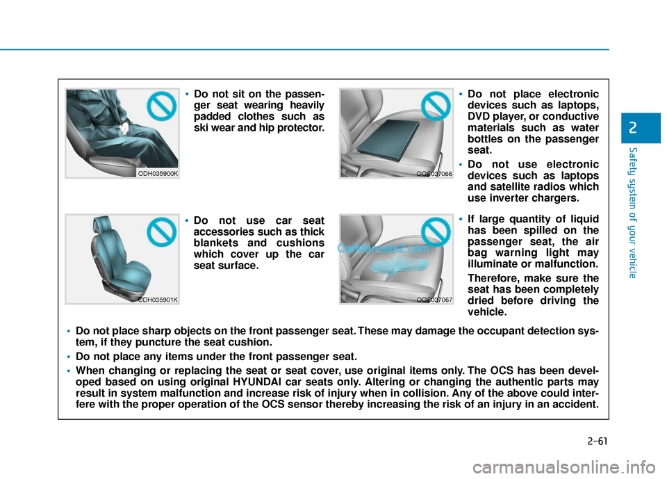
Do not sit on the passen-
ger seat wearing heavily
padded clothes such as
ski wear and hip protector.
Do not use car seat
accessories such as thick
blankets and cushions
which cover up the car
seat surface.
Do not place electronic
devices such as laptops,
DVD player, or conductive
materials such as water
bottles on the passenger
seat.
Do not use electronic
devices such as laptops
and satellite radios which
use inverter chargers.
If large quantity of liquid
has been spilled on the
passenger seat, the air
bag warning light may
illuminate or malfunction.
Therefore, make sure the
seat has been completely
dried before driving the
vehicle.
Do not place sharp objects on the front passenger seat. These may damage the occupant detection sys-
tem, if they puncture the seat cushion.
Do not place any items under the front passenger seat.
When changing or replacing the seat or seat cover, use original items only. The OCS has been devel-
oped based on using original HYUNDAI car seats only. Altering or changing the authentic parts may
result in system malfunction and increase risk of injury when in collision. Any of the above could inter-
fere with the proper operation of the OCS sensor thereby increasing the risk of an injury in an accident.
Page 86 of 540
Driver Assist System .........................................3-112
Rear View Monitor ......................................................3-112
Parking Distance Warning (Reverse) System ........3-113
Automatic Climate Control System ..................3-117
Automatic Temperature Control Mode ....................3-118
Manual Temperature Control Mode .........................3-119
System Operation .........................................................3-126
System Maintenance....................................................3-128
Windshield Defrosting and Defogging ............3-130
To Defog Inside Windshield .....................................3-130
To Defrost Outside Windshield ..................................3-131
Defogging logic ............................................................3-131
Auto Defogging System ..............................................3-131
Rear Window Defroster ..............................................3-133
Climate Control Additional Features ...............3-134
Cluster ionizer ..............................................................3-134
Automatic Ventilation ...................................................3-134
Sunroof Inside Air Recirculation ...............................3-134
Storage Compartment .......................................3-135
Center Console Storage ..............................................3-135
Glove Box ........................................................................\
3-135
Sunglass Holder ...........................................................3-135
Interior Features ................................................3-137
Cup Holder ......................................................................3-\
137
Sunvisor ........................................................................\
...3-138
Power Outlet ..................................................................3-139
USB Charger .................................................................3-140
Wireless Cellular Phone Charging System..............3-140
Clock ........................................................................\
.........3-142
Coat Hook .......................................................................3\
-143
Floor Mat Anchor(s).....................................................3-143
Luggage Net Holder .....................................................3-144
Cargo Area Cover..........................................................3-145
3
Page 154 of 540
3-70
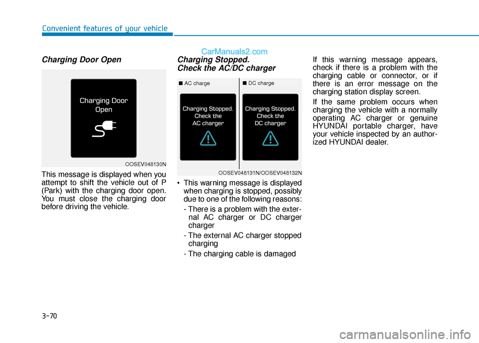
Charging Door Open
This message is displayed when you
attempt to shift the vehicle out of P
(Park) with the charging door open.
You must close the charging door
before driving the vehicle.
Charging Stopped.Check the AC/DC charger
This warning message is displayed
when charging is stopped, possibly
due to one of the following reasons:
- There is a problem with the exter-nal AC charger or DC charger
charger
- The external AC charger stopped charging
- The charging cable is damaged If this warning message appears,
check if there is a problem with the
charging cable or connector, or if
there is an error message on the
charging station display screen.
If the same problem occurs when
charging the vehicle with a normally
operating AC charger or genuine
HYUNDAI portable charger, have
your vehicle inspected by an author-
ized HYUNDAI dealer.
Convenient features of your vehicle
OOSEV048130N
OOSEV048131N/OOSEV048132N
■
AC charge■DC charge
Page 155 of 540
3-71
Convenient features of your vehicle
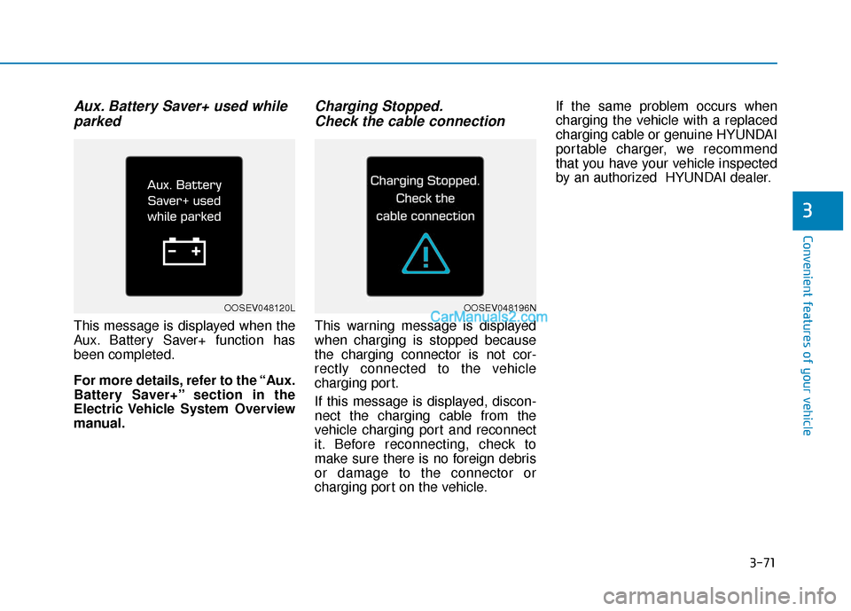
Aux. Battery Saver+ used whileparked
This message is displayed when the
Aux. Battery Saver+ function has
been completed.
For more details, refer to the “Aux.
Battery Saver+” section in the
Electric Vehicle System Overview
manual.
Charging Stopped.Check the cable connection
This warning message is displayed
when charging is stopped because
the charging connector is not cor-
rectly connected to the vehicle
charging port.
If this message is displayed, discon-
nect the charging cable from the
vehicle charging port and reconnect
it. Before reconnecting, check to
make sure there is no foreign debris
or damage to the connector or
charging port on the vehicle. If the same problem occurs when
charging the vehicle with a replaced
charging cable or genuine HYUNDAI
portable charger, we recommend
that you have your vehicle inspected
by an authorized HYUNDAI dealer.
3
OOSEV048120LOOSEV048196N
Page 224 of 540
3-140
Convenient features of your vehicle
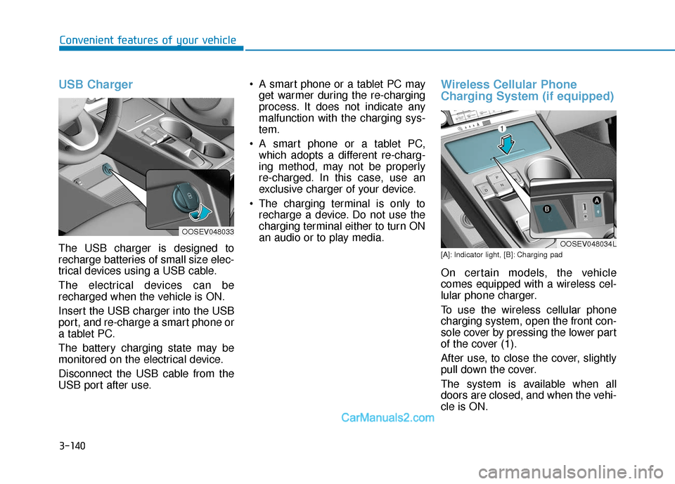
USB Charger
The USB charger is designed to
recharge batteries of small size elec-
trical devices using a USB cable.
The electrical devices can be
recharged when the vehicle is ON.
Insert the USB charger into the USB
port, and re-charge a smart phone or
a tablet PC.
The battery charging state may be
monitored on the electrical device.
Disconnect the USB cable from the
USB port after use. A smart phone or a tablet PC may
get warmer during the re-charging
process. It does not indicate any
malfunction with the charging sys-
tem.
A smart phone or a tablet PC, which adopts a different re-charg-
ing method, may not be properly
re-charged. In this case, use an
exclusive charger of your device.
The charging terminal is only to recharge a device. Do not use the
charging terminal either to turn ON
an audio or to play media.
Wireless Cellular Phone
Charging System (if equipped)
[A]: Indicator light, [B]: Charging pad
On certain models, the vehicle
comes equipped with a wireless cel-
lular phone charger.
To use the wireless cellular phone
charging system, open the front con-
sole cover by pressing the lower part
of the cover (1).
After use, to close the cover, slightly
pull down the cover.
The system is available when all
doors are closed, and when the vehi-
cle is ON.
OOSEV048033
OOSEV048034L
Page 405 of 540
7-25
7
Maintenance
By jump starting
After a jump start from a good bat-
tery, drive the vehicle for 20-30 min-
utes before it is shutoff. The vehicle
may not restart if you shut it off
before the battery had a chance to
adequately recharge. See "Jump
Starting" in chapter 6 for more infor-
mation on jump starting procedures.
Information
An inappropriately disposedbattery can be harmful to
the environment and human
health. Dispose of the bat-
tery according to your local
law(s) or regulation.
Reset Features
Some items need to be reset after
the battery has been discharged or
the battery has been disconnected.
Power Windows
Trip Computer
Climate Control System
Clock
Audio System
Sunroof
i
Watch the battery during
charging, and stop or reduce
the charging rate if the battery
cells begin boiling violently.
The negative battery cable
must be removed first and
installed last when the battery
is disconnected. Disconnect
the battery charger in the fol-
lowing order:
(1) Turn off the battery charg-
er main switch.
(2) Unhook the negative
clamp from the negative
battery terminal.
(3) Unhook the positive clamp from the positive battery
terminal.
Always use a genuine
HYUNDAI approved battery
when you replace the battery.
Page 427 of 540
7-47
7
Maintenance
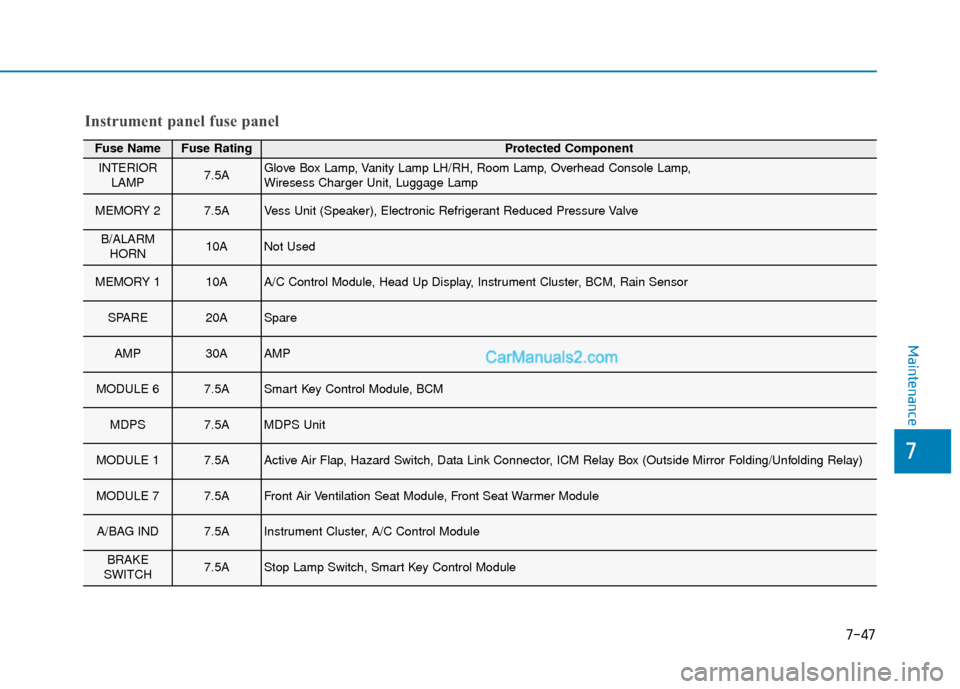
Fuse NameFuse RatingProtected Component
INTERIORLAMP7.5AGlove Box Lamp, Vanity Lamp LH/RH, Room Lamp, Overhead Console Lamp,
Wiresess Charger Unit, Luggage Lamp
MEMORY 27.5AVess Unit (Speaker), Electronic Refrigerant Reduced Pressure Valve
B/ALARMHORN10ANot Used
MEMORY 110AA/C Control Module, Head Up Display, Instrument Cluster, BCM, Rain Sensor
SPARE20ASpare
AMP30AAMP
MODULE 67.5ASmart Key Control Module, BCM
MDPS7.5AMDPS Unit
MODULE 17.5AActive Air Flap, Hazard Switch, Data Link Connector, ICM Relay Box (Outside Mirror Folding/Unfolding Relay)
MODULE 77.5AFront Air Ventilation Seat Module, Front Seat Warmer Module
A/BAG IND7.5AInstrument Cluster, A/C Control Module
BRAKE
SWITCH7.5AStop Lamp Switch, Smart Key Control Module
Instrument panel fuse panel
Page 429 of 540
7-49
7
Maintenance
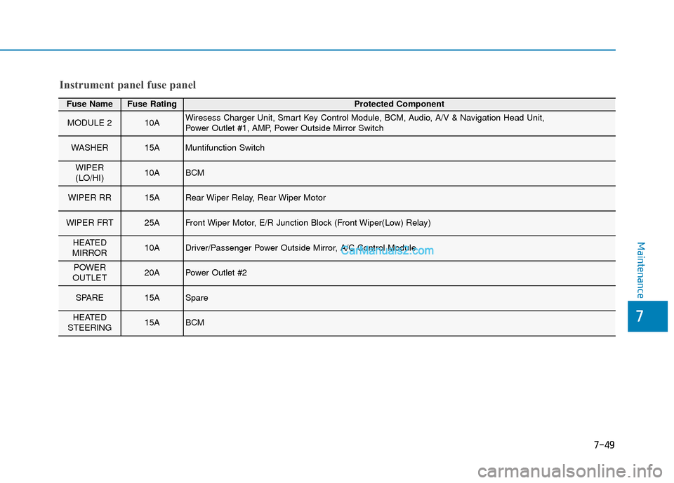
Fuse NameFuse RatingProtected Component
MODULE 210AWiresess Charger Unit, Smart Key Control Module, BCM, Audio, A/V & Navigation Head Unit,
Power Outlet #1, AMP, Power Outside Mirror Switch
WASHER15AMuntifunction Switch
WIPER
(LO/HI)10ABCM
WIPER RR15ARear Wiper Relay, Rear Wiper Motor
WIPER FRT25AFront Wiper Motor, E/R Junction Block (Front Wiper(Low) Relay)
HEATED
MIRROR10ADriver/Passenger Power Outside Mirror, A/C Control Module
POWER
OUTLET20APower Outlet #2
SPARE15ASpare
HEATED
STEERING15ABCM
Instrument panel fuse panel
Page 431 of 540
7-51
7
Maintenance
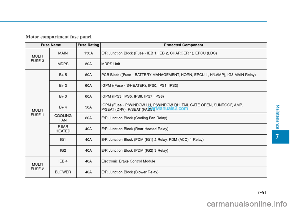
Motor compartment fuse panel
Fuse NameFuse RatingProtected Component
MULTI
FUSE-3MAIN150AE/R Junction Block (Fuse - IEB 1, IEB 2, CHARGER 1), EPCU (LDC)
MDPS80AMDPS Unit
MULTI
FUSE-1
B+ 560APCB Block ((Fuse - BATTERY MANAGEMENT, HORN, EPCU 1, H/LAMP), IG3 MAIN Relay)
B+ 260AIGPM ((Fuse - S/HEATER), IPS0, IPS1, IPS2)
B+ 360AIGPM (IPS3, IPS5, IPS6, IPS7, IPS8)
B+ 450AIGPM (Fuse - P/WINDOW LH, P/WINDOW RH, TAIL GATE OPEN, SUNROOF, AMP,
P/SEAT (DRV), P/SEAT (PASS))
COOLING FA N60AE/R Junction Block (Cooling Fan Relay)
REAR
HEATED40AE/R Junction Block (Rear Heated Relay)
IG140AE/R Junction Block (PDM (IG1) 2 Relay, PDM (ACC) 1 Relay)
IG240AE/R Junction Block (PDM (IG2) 3 Relay)
MULTI
FUSE-2IEB 440AElectronic Brake Control Module
BLOWER40AE/R Junction Block (Blower Relay)
Page 432 of 540
7-52
Maintenance
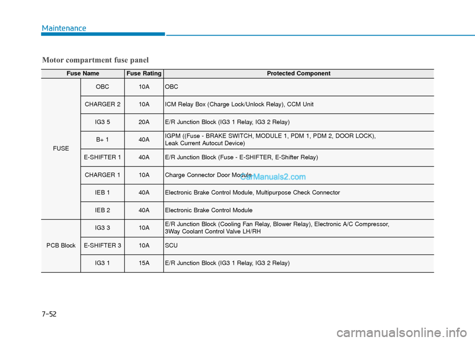
Motor compartment fuse panel
Fuse NameFuse RatingProtected Component
FUSE
OBC10AOBC
CHARGER 210AICM Relay Box (Charge Lock/Unlock Relay), CCM Unit
IG3 520AE/R Junction Block (IG3 1 Relay, IG3 2 Relay)
B+ 140AIGPM ((Fuse - BRAKE SWITCH, MODULE 1, PDM 1, PDM 2, DOOR LOCK),
Leak Current Autocut Device)
E-SHIFTER 140AE/R Junction Block (Fuse - E-SHIFTER, E-Shifter Relay)
CHARGER 110ACharge Connector Door Module
IEB 140AElectronic Brake Control Module, Multipurpose Check Connector
IEB 240AElectronic Brake Control Module
PCB Block
IG3 310AE/R Junction Block (Cooling Fan Relay, Blower Relay), Electronic A/C Compressor,
3Way Coolant Control Valve LH/RH
E-SHIFTER 310ASCU
IG3 115AE/R Junction Block (IG3 1 Relay, IG3 2 Relay)