engine coolant Hyundai Matrix 2005 User Guide
[x] Cancel search | Manufacturer: HYUNDAI, Model Year: 2005, Model line: Matrix, Model: Hyundai Matrix 2005Pages: 407, PDF Size: 10.31 MB
Page 115 of 407

OWNER MAINTENANCE
6-8 CAUTION: Slowly loosen the oil filter upper cap not to overflow the oil.
4. Remove the engine oil filler cap.
5. Slide underneath the car and loosen the oil pan drain plug by turning it counterclock- wise oil pan with a wrench of the propersize. Be sure that a drain pan is in positionto catch the oil as it drains out, then removethe drain plug.
WARNING: Be very careful when draining the engine oil as it may be hot enough to burn you!
6. When the oil has stopped draining, replace the drain plug using a new gasket andretighten by turning it clockwise. Oil pan drain plug tightening torque : 3.5 ~ 4.5 kgf.m
7. Pull out the oil filter upper cap with element from the oil filter housing.Using a clean cloth, remove any dirt or oil accumulated around the oil filter housing.
8. After mounting a new centrepipe O-ring, new oil filter element and new O-ring toupper cap, install the upper cap to oil filterhousing and retighten by turning it clock-wise. Do not over-tighten. Tightening torque : 2.5 kgf.m CAUTION: Don't use old oil filter upper cap O-ring
and centrepipe O-ring.
9. Refill the crankcase with the recommended engine oil. Refer to the specification in chapter 9 for engine oil capacity.
CAUTION: Slowly pour the recommended oil by us-
ing a funnel. Do not overfill not to damage the engine.
10.Start the engine and check to be sure no oil is leaking from the drain plug or oil filter.
11.Shut off the engine and recheck the oil level.
NOTE:
o It is recommended that the engine oil and filter should be changed by an Hyundai authorised repairer.
o Always dispose of used engine oil in an environmentally acceptable man-ner. It is suggested that it be placed ina sealed container and taken to a ser-vice station for maybe reclaimation.Do not pour the oil on the ground orput it into the household trash.
WARNING: Used motor oil may cause irritation or
cancer of the skin if left in contact with the skin for prolonged periods of time.Wash your hands thoroughly with soapand warm water as soon as possible afterhandling used oil.
Centrepipe O-ring
G040B02FC
O-ring
Oil filter housing
2. Open the bonnet and remove the engine oil level dipstick.
3. Loosen the oil filter upper cap with a proper tool from the oil filter housing until an O-ring is seen. Then, drain the oil completely.
Oil filter element
Upper cap
If the car is being driven in severe conditions,
more frequent oil and filter changes are re-quired.
The procedure for changing the oil and filter
is as follows:
1. Park the car on level ground and set the parking brake. Start the engine and let it warm up until the needle on the coolanttemperature gauge moves above the low-est mark. Turn the engine off and place thegear selector lever in "P" (automatic) orreverse gear (manual transaxle).
Page 116 of 407
OWNER MAINTENANCE 6-9
SG050A1-E
ENGINE COOLANT CHECKING
AND REPLACING WARNING: Do not remove the radiator cap when the
engine is hot, since the system is pressurised and coolant may be ejectedfrom the radiator resulting in scalding.
SG050B1-E
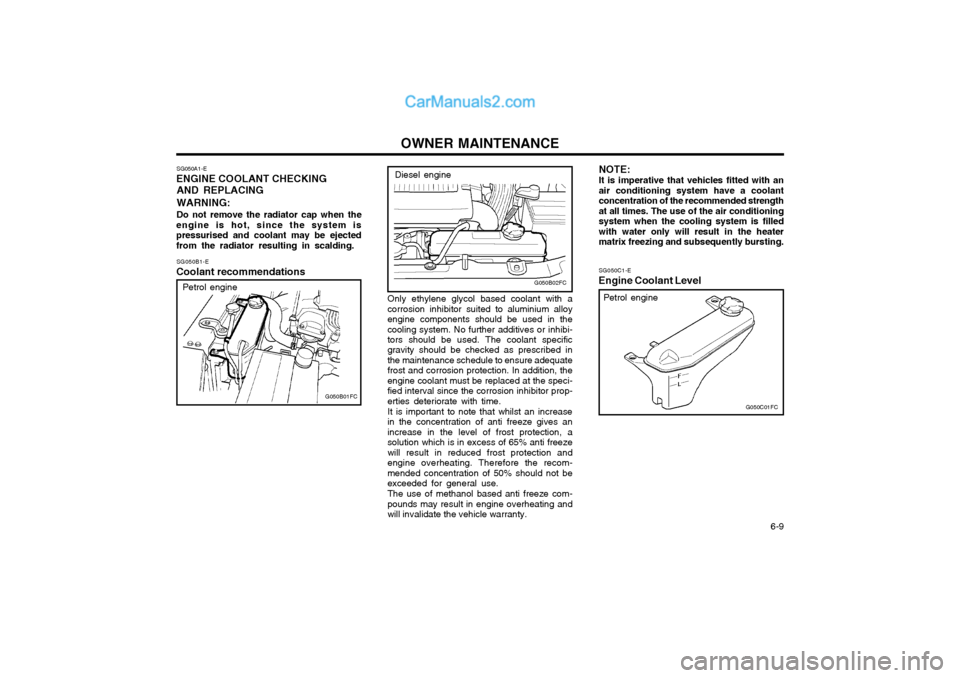
Coolant recommendations
Petrol engine
G050B01FC SG050C1-E
Engine Coolant LevelG050C01FC
Petrol engine
NOTE: It is imperative that vehicles fitted with an air conditioning system have a coolantconcentration of the recommended strengthat all times. The use of the air conditioningsystem when the cooling system is filledwith water only will result in the heatermatrix freezing and subsequently bursting.Diesel engine
Only ethylene glycol based coolant with a corrosion inhibitor suited to aluminium alloyengine components should be used in thecooling system. No further additives or inhibi- tors should be used. The coolant specific gravity should be checked as prescribed inthe maintenance schedule to ensure adequatefrost and corrosion protection. In addition, theengine coolant must be replaced at the speci-fied interval since the corrosion inhibitor prop-erties deteriorate with time. It is important to note that whilst an increase in the concentration of anti freeze gives anincrease in the level of frost protection, asolution which is in excess of 65% anti freezewill result in reduced frost protection andengine overheating. Therefore the recom-mended concentration of 50% should not beexceeded for general use. The use of methanol based anti freeze com- pounds may result in engine overheating andwill invalidate the vehicle warranty.
G050B02FC
Page 117 of 407
OWNER MAINTENANCE
6-10 SG050D1-E
To Change the Coolant
The coolant should be changed at those
intervals specified in the vehicle maintenance schedule in Section 5.
NOTE: Care should be taken to ensure that cool-
ant is not allowed to spill onto the paintwork since the finish may becomedamaged. If coolant spillage occurs, theaffected area should be rinsed thoroughlywith water.
1. Park the vehicle on level ground and en- sure that the parking brake is firmly ap- plied, and the engine allowed to cool. Do not attempt this operation whilst the engine is hot since burning or scaldingmay result.
2. Prepare a suitable receptacle to collect the displaced coolant and position this underthe radiator drain tap.
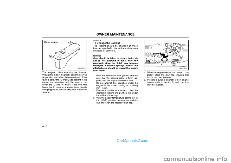
3. With the heater temperature control set to the "HOT" position, remove the radiatorcap and open the radiator drain tap. 4. When the engine coolant has drained com-
pletely, close the drain tap ensuring thatthis is not over tightened.
5. Prepare a suitable quantity of new engine coolant (refer to section 9) and pour thisinto the radiator.
G050D01FC
The engine coolant level may be observed through the side of the plastic coolant reservoir(expansion tank) when the engine is cold. If thelevel is below the "L" mark, add coolant of thecorrect concentration until the level is be-tween the "L" and "F" marks. If the level fallsbelow the "L" mark on a regular basis despitebeing topped up, consult a Hyundai authorisedrepairer.
G050C02FC
Diesel engine
Page 118 of 407
OWNER MAINTENANCE 6-11
6. Start the engine with the radiator cap still
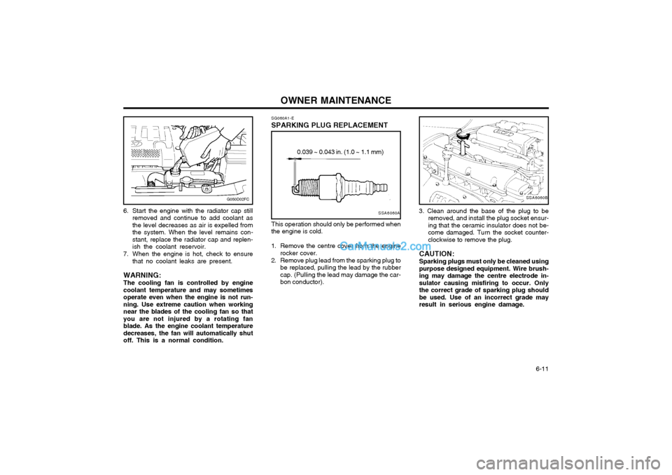
removed and continue to add coolant as the level decreases as air is expelled fromthe system. When the level remains con-stant, replace the radiator cap and replen-ish the coolant reservoir.
7. When the engine is hot, check to ensure that no coolant leaks are present.
WARNING: The cooling fan is controlled by engine coolant temperature and may sometimesoperate even when the engine is not run-ning. Use extreme caution when workingnear the blades of the cooling fan so thatyou are not injured by a rotating fanblade. As the engine coolant temperaturedecreases, the fan will automatically shutoff. This is a normal condition.
G050D02FCSSA6060B
3. Clean around the base of the plug to be removed, and install the plug socket ensur- ing that the ceramic insulator does not be-come damaged. Turn the socket counter-clockwise to remove the plug.
CAUTION: Sparking plugs must only be cleaned using purpose designed equipment. Wire brush-ing may damage the centre electrode in-sulator causing misfiring to occur. Onlythe correct grade of sparking plug shouldbe used. Use of an incorrect grade mayresult in serious engine damage.
SG060A1-E
SPARKING PLUG REPLACEMENT
SSA6060A
0.039 ~ 0.043 in. (1.0 ~ 1.1 mm)
This operation should only be performed when
the engine is cold.
1. Remove the centre cover from the engine rocker cover.
2. Remove plug lead from the sparking plug to be replaced, pulling the lead by the rubber cap. (Pulling the lead may damage the car-bon conductor).
Page 120 of 407
OWNER MAINTENANCE 6-13
G080A01A-EAT
WINDSCREEN WIPER BLADES CAUTION:
o The air flow sensor is a precision engi- neered electronic measuring device and therefore care should be exercised thatthe air flow sensor is not damagedduring replacement of the element.
o When removing the air cleaner ele- ment, be careful that dust or dirt doesnot enter the air intake. These mayresult in damage to the air cleanerelement.
To ensure maximum filtration performance
and continued engine performance, only genu-ine Hyundai replacements should be used.
HEF-119-E
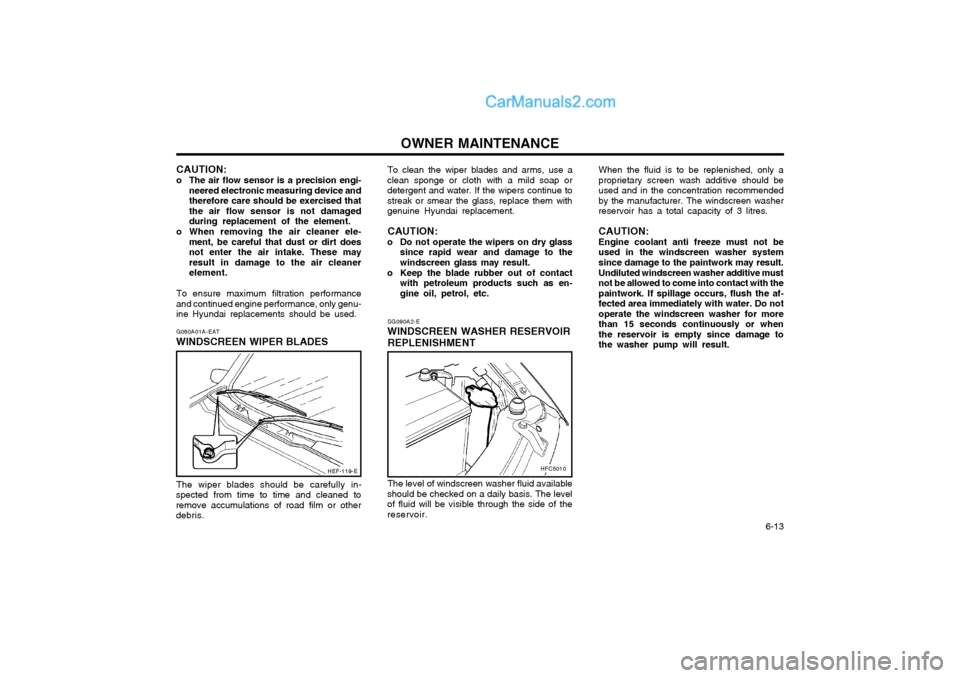
The wiper blades should be carefully in-
spected from time to time and cleaned to remove accumulations of road film or otherdebris. When the fluid is to be replenished, only aproprietary screen wash additive should beused and in the concentration recommendedby the manufacturer. The windscreen washerreservoir has a total capacity of 3 litres. CAUTION: Engine coolant anti freeze must not be used in the windscreen washer systemsince damage to the paintwork may result. Undiluted windscreen washer additive must not be allowed to come into contact with thepaintwork. If spillage occurs, flush the af-fected area immediately with water. Do notoperate the windscreen washer for morethan 15 seconds continuously or whenthe reservoir is empty since damage tothe washer pump will result.
To clean the wiper blades and arms, use a
clean sponge or cloth with a mild soap ordetergent and water. If the wipers continue tostreak or smear the glass, replace them withgenuine Hyundai replacement.
CAUTION:
o Do not operate the wipers on dry glass since rapid wear and damage to thewindscreen glass may result.
o Keep the blade rubber out of contact with petroleum products such as en-gine oil, petrol, etc.
SG090A2-E
WINDSCREEN WASHER RESERVOIR
REPLENISHMENT
The level of windscreen washer fluid available
should be checked on a daily basis. The level of fluid will be visible through the side of thereservoir.
HFC5010
Page 123 of 407
OWNER MAINTENANCE
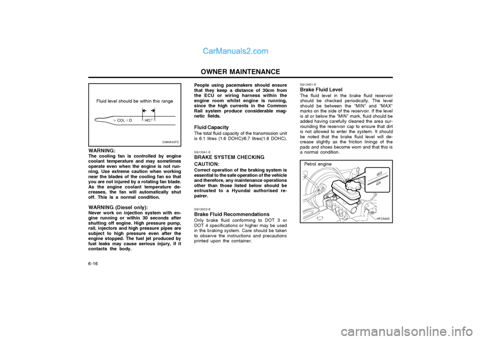
6-16 SG120D1-E Brake Fluid Level The fluid level in the brake fluid reservoir should be checked periodically. The levelshould be between the "MIN" and "MAX"marks on the side of the reservoir. If the levelis at or below the "MIN" mark, fluid should beadded having carefully cleaned the area sur-rounding the reservoir cap to ensure that dirtis not allowed to enter the system. It shouldbe noted that the brake fluid level will de-crease slightly as the friction linings of thepads and shoes become worn and that this isa normal condition.
SG120A1-E
BRAKE SYSTEM CHECKING CAUTION:
Correct operation of the braking system is
essential to the safe operation of the vehicle and therefore, any maintenance operationsother than those listed below should beentrusted to a Hyundai authorised re-pairer.
SG120C2-E
Brake Fluid Recommendations
Only brake fluid conforming to DOT 3 or
DOT 4 specifications or higher may be usedin the braking system. Care should be takento observe the instructions and precautionsprinted upon the container.
HFC5005
Petrol engine
People using pacemakers should ensure that they keep a distance of 30cm fromthe ECU or wiring harness within theengine room whilst engine is running,since the high currents in the CommonRail system produce considerable mag-netic fields. Fluid Capacity The total fluid capacity of the transmission unit is 6.1 litres (1.6 DOHC)/6.7 litres(1.8 DOHC).
Fluid level should be within this range
C090A03FC
�Î�Î
WARNING: The cooling fan is controlled by engine
coolant temperature and may sometimes operate even when the engine is not run-ning. Use extreme caution when workingnear the blades of the cooling fan so thatyou are not injured by a rotating fan blade.As the engine coolant temperature de-creases, the fan will automatically shutoff. This is a normal condition.
WARNING (Diesel only): Never work on injection system with en-
gine running or within 30 seconds after shutting off engine. High pressure pump,rail, injectors and high pressure pipes aresubject to high pressure even after theengine stopped. The fuel jet produced byfuel leaks may cause serious injury, if itcontacts the body.
Page 129 of 407

OWNER MAINTENANCE
6-22 SG230A1-E POWER STEERING FLUID LEVEL
HFC5004
G230A02FC
Petrol engine
Diesel engine
The power steering fluid level should be checked daily.
SG220A1-E ELECTRIC COOLING FANS WARNING: The cooling fan is controlled by engine coolant temperature and may sometimesoperate even when the engine is not run-ning. Use extreme caution when workingnear the blades of the cooling fan so thatyou are not injured by a rotating fan blade.As the engine coolant temperature decreas-es, the fan will automatically shut off. Thisis a normal condition. The engine cooling fan should operate before the temperature gauge reaches the upper por-tion of the scale and the condenser fan shouldoperate whenever the air conditioning is in use.
o Batteries must only be charged in well
ventilated areas from which naked lights orsources of sparks are excluded.
o Ensure that children, pets or other unauthorised persons are kept away frombatteries.
o Do not allow anything to bridge the positive (+) and negative (-) terminals of the battery.
o Never invert the battery. The battery fitted during production is of the "Maintenance Free" type.
Page 132 of 407
OWNER MAINTENANCE 6-25
5. Push the bulb spring for removing the
headlight bulb.
6. Remove the protective cap from the re- placement bulb and install the new bulb by matching the plastic base with the headlighthole. Install the dust cover after retighteningthe bulb spring and reconnect the powercord.
7. Use the protective cap and carton to dis- pose of the old bulb.
8. Check for proper headlight aim.
WARNING The halogen bulb contains gas under
pressure and if impacted could shatter, resulting in flying fragments. Always weareye protection when servicing the bulb.
G270A02FC
3. Disconnect the power cord from the bulb base in the back of the headlight.
4. Remove the dust cover.
5. Open the bonnet.
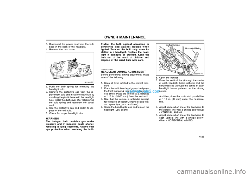
6. Draw the vertical line (through the centreof each headlight beam pattern) and the horizontal line (through the centre of eachheadlight beam pattern) on the aimingscreen. And then, draw the horizontal parallel line at 1.18 in. (30 mm) under the horizontalline.
7. Adjust each cut-off line of the low beam to the parallel line with a phillips screwdriver- VERTICAL AIMING
8. Adjust each cut-off line of the low beam to each vertical line with a phillips screw-driver - HORIZONTAL AIMING.
G290A01FC-EAT
HEADLIGHT AIMING ADJUSTMENT
Before performing aiming adjustment, makesure of the following.
1. Keep all tyres inflated to the correct pres- sure.
2. Place the vehicle on level ground and press the front bumper & rear bumper down sev-eral times. Place the vehicle at a distanceof 118 in. (3,000 mm) from the test wall.
3. See that the vehicle is unloaded (except for full levels of coolant, engine oil and fuel,and spare tyre, jack, and tools).
4. Clean the head lights lens and turn on the headlight (Low beam).
G290A01FC
Horizontal Aiming
Vertical Aiming
Protect the bulb against abrasions or scratches and against liquids whenlighted. Turn on the bulb only when in-stalled in a headlight. Replace the head-light if damaged or cracked. Keep thebulb out of the reach of children anddispose of the used bulb with care.
Page 139 of 407
EMISSION CONTROL SYSTEM 7-1
SH000A1-E
7. EMISSION
CONTROL SYSTEM
SH010A1-E EMISSION CONTROL SYSTEMS (Not all models) Depending upon the market for which the ve-hicle is destined, the emission control systemwill comprise one or more of the followingemission control devices. (1) Crankcase emission control system (2) Evaporative emission control system (3) Exhaust emission control system In order that the proper functioning of the emis- sion control systems may be ensured, it isrecommended that the vehicle is inspected andmaintained by an Hyundai authorised repairerin accordance with the maintenance schedulein this manual. SH010B1-E 1. CRANKCASE EMISSION CONTROL SYSTEM
The positive crankcase ventilation system is employed to prevent air pollution caused byblow-by gases being emitted from the crank-case by introducing fresh air to the crankcase through the air cleaner where this mixes withblow-by gases and then passes through thePCV valve into the intake manifold from whereit subsequently enters the combustion cham-ber and is burned.
SH010D1-E 3. EXHAUST EMISSION CONTROL SYSTEM The exhaust emission control system is a highlyeffective system which controls exhaust emis-sion whilst maintaining good vehicle perfor-mance.
SH010C1-E
2. EVAPORATIVE EMISSION
CONTROL SYSTEM
The Evaporative Emission Control System is designed to prevent fuel vapours from escap-ing into the atmosphere through the fuel tankventilation system.Whilst the engine is not running, fuel vapoursgenerated inside the fuel tank are absorbedand stored in a charcoal canister. When theengine is started, the vapours stored in thecanister are drawn into the induction systemthrough the purge control solenoid valve andare subsequently burned.The purge control solenoid valve is controlledby the ECU; when the engine coolant tempera-ture is low or the engine is idling, the purgecontrol valve is closed and fuel vapours remainstored in the canister. Under normal runningconditions when the engine is warm, the valveopens and the vapours are drawn into the inlettract and subsequently burned in the combus-tion chamber. SH020A1-E
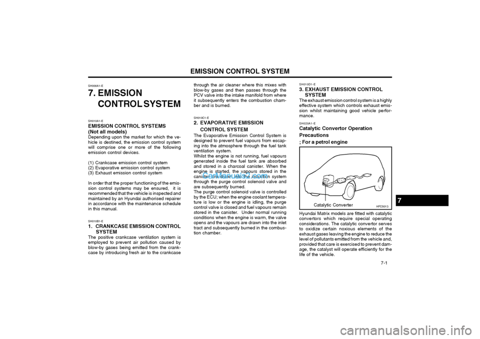
Catalytic Convertor Operation Precautions; For a petrol engine Hyundai Matrix models are fitted with catalytic convertors which require special operatingconsiderations. The catalytic convertor servesto oxidize certain noxious elements of theexhaust gases leaving the engine to reduce thelevel of pollutants emitted from the vehicle and,provided that care is exercised to prevent dam-age, the catalyst will operate efficiently for thelife of the vehicle.
7HFC5013
Catalytic Converter
Page 146 of 407

VEHICLE SPECIFICATIONS 9-3
Oil & Grease Standard
API SJ, SL SAE 5W-20, 5W-30
or ABOVE, SAE 10W-30 (ABOVE 0°F)
ILSAC GF-3 SAE 15W-40 (ABOVE 10°F)
or ABOVE SAE 20W-50 (ABOVE 20°F)
API CH-4 SAE 30 (0°C ~ 40°C)
or ABOVE, SAE 20W-40 (ABOVE -10°C)
ACEA B4 SAE 15W-40 (ABOVE -15°C)
or ABOVE SAE 10W-30 (-20°C ~ 40°C)
SAE 5W-30 (-25°C ~ 10°C) SAE 0W-30 (BELOW 10°C) *1, *2
*1. Restricted to driving condition and vehicle destination*2. Not recommended for sustained high speed vehicle operation Normal driving conditionSevere driving condition HYUNDAI GENUINE PARTS MTF 75W/85 (API GL-4) HYUNDAI GENUINE ATF SP-III, DIAMOND ATF SP-III,SK ATF SP-III or other brands approved by Hyundai Motor Co., PSF-3 or Dexron 2 DOT 3, DOT 4 or equivalent Ethylene glycol base for aluminium radiator
Item
Engine Oil (Petrol engine) Engine Oil (Diesel engine) Engine Oil Consumption Transaxle
Power Steering Brake Fluid Coolant
J080A06FC-EAT LUBRICATION CHART
Q'ty (Imp.qts) (litre)
1.6 DOHC - 2.9 (3.3) (with oil filter) 1.8 DOHC - 3.5 (4.0) (with oil filter) 1.5 CRDi - 4.7 (5.3) (with oil filter) MAX. 1L /932 Miles (1500 Km) MAX. 1L /621 Miles (1000 Km)
1.86 (2.15)/1.76 (2.0) (1.5 CRDi) 5.3 (6.1) (1.6 DOHC)/
5.8 (6.7)(1.8 DOHC)As required As required
Petol engine : 5.4 (6.2) (1.6 DOHC)/5.7 (6.5) (1.8 DOHC)Diesel engine : 5.5 (6.3)
Manual Auto