check engine Hyundai Matrix 2005 Service Manual
[x] Cancel search | Manufacturer: HYUNDAI, Model Year: 2005, Model line: Matrix, Model: Hyundai Matrix 2005Pages: 407, PDF Size: 10.31 MB
Page 127 of 407

OWNER MAINTENANCE
6-20 SG200A1-E
FUSIBLE LINKS
AS60310A
Bad
Good
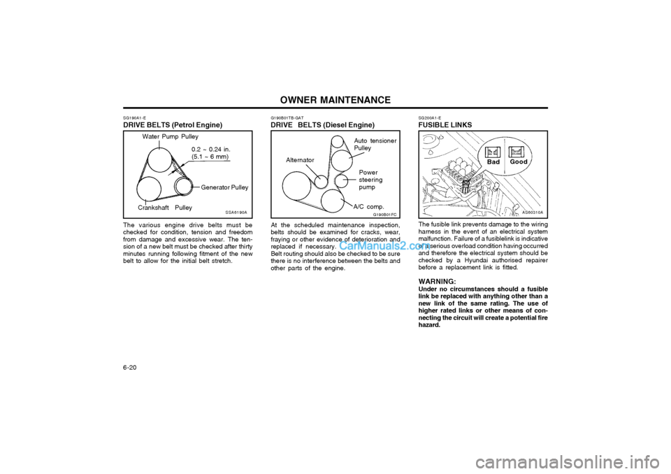
The fusible link prevents damage to the wiring harness in the event of an electrical systemmalfunction. Failure of a fusiblelink is indicativeof a serious overload condition having occurredand therefore the electrical system should bechecked by a Hyundai authorised repairerbefore a replacement link is fitted. WARNING: Under no circumstances should a fusible link be replaced with anything other than anew link of the same rating. The use ofhigher rated links or other means of con-necting the circuit will create a potential firehazard.
G190B01TB-GAT
DRIVE BELTS (Diesel Engine)
At the scheduled maintenance inspection,belts should be examined for cracks, wear,fraying or other evidence of deterioration andreplaced if necessary.Belt routing should also be checked to be surethere is no interference between the belts andother parts of the engine.G190B01FC
Auto tensioner Pulley Powersteeringpump
A/C comp.
Alternator
SG190A1-E
DRIVE BELTS (Petrol Engine)
SSA6190A
Water Pump Pulley
Generator Pulley
Crankshaft Pulley 0.2 ~ 0.24 in. (5.1 ~ 6 mm)
The various engine drive belts must be checked for condition, tension and freedomfrom damage and excessive wear. The ten-sion of a new belt must be checked after thirtyminutes running following fitment of the newbelt to allow for the initial belt stretch.
Page 129 of 407

OWNER MAINTENANCE
6-22 SG230A1-E POWER STEERING FLUID LEVEL
HFC5004
G230A02FC
Petrol engine
Diesel engine
The power steering fluid level should be checked daily.
SG220A1-E ELECTRIC COOLING FANS WARNING: The cooling fan is controlled by engine coolant temperature and may sometimesoperate even when the engine is not run-ning. Use extreme caution when workingnear the blades of the cooling fan so thatyou are not injured by a rotating fan blade.As the engine coolant temperature decreas-es, the fan will automatically shut off. Thisis a normal condition. The engine cooling fan should operate before the temperature gauge reaches the upper por-tion of the scale and the condenser fan shouldoperate whenever the air conditioning is in use.
o Batteries must only be charged in well
ventilated areas from which naked lights orsources of sparks are excluded.
o Ensure that children, pets or other unauthorised persons are kept away frombatteries.
o Do not allow anything to bridge the positive (+) and negative (-) terminals of the battery.
o Never invert the battery. The battery fitted during production is of the "Maintenance Free" type.
Page 130 of 407

OWNER MAINTENANCE 6-23
To check the power steering fluid level, be
sure the ignition is "OFF", then check to make certain that the power steering fluid level isbetween the "MAX" and "MIN" level markingson the fluid reservoir.
NOTE: Grinding noise from power steering pump
may be heard immediately after the engine is started in extremely cold condition(below -4°F). If the noise stops during warmup, there is no abnormal function in thesystem. This is due to a power steeringfluid characteristic in extremely cold con-ditions. FLUID RECOMMENDATION
Only automatic transmission fluid meeting the
specification of PSF-3 or Dexron 2 should be used in the power steering system. SG230B1-E POWER STEERING HOSES Power steering hoses should be checked for damage, deterioration and leakage at each ser-vice.
G350B01FC-GAT
BLEEDING THE FUEL SYSTEM (Diesel engine)
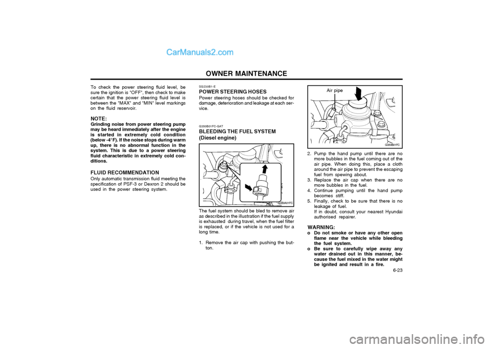
The fuel system should be bled to remove air
as described in the illustration if the fuel supply is exhausted during travel, when the fuel filteris replaced, or if the vehicle is not used for along time.
1. Remove the air cap with pushing the but- ton.
G350A01FC
G350B01FC
2. Pump the hand pump until there are no more bubbles in the fuel coming out of the air pipe. When doing this, place a clotharound the air pipe to prevent the escapingfuel from spewing about.
3. Replace the air cap when there are no more bubbles in the fuel.
4. Continue pumping until the hand pump becomes stiff.
5. Finally, check to be sure that there is no leakage of fuel. If in doubt, consult your nearest Hyundai authorised repairer.
WARNING:
o Do not smoke or have any other open flame near the vehicle while bleedingthe fuel system.
o Be sure to carefully wipe away any water drained out in this manner, be-cause the fuel mixed in the water mightbe ignited and result in a fire.
Air pipe
Page 131 of 407

OWNER MAINTENANCE
6-24 G270A02A-GAT HEADLIGHT BULB Replacement instructions:
G270A01FC
1. Allow the bulb to cool. Wear eye protection.
2. Always grasp the bulb by its plastic base, avoid touching the glass.
SG250A1-E
REPLACING LIGHT BULBS
In the event of bulb failure being experienced, ensure that the relative lighting circuit is turnedoff prior to attempting to replace the bulb. Theillustrations on the following page will assist inlocating and removing the various bulbs. En-sure that the replacement bulb has the samecap configuration and wattage as the original. CAUTION: Keep the lamps out of contact with petro- leum products, such as oil, petrol, etc.
1. Loosen the drain plug at the bottom of the
fuel filter.
2. Tighten the drain plug when water no longer comes out.
3. Check to be sure that the warning lamp illuminates when the ignition key is turnedto "ON", and that it goes off when theengine is started. If in doubt, consult your nearest Hyundai authorised repairer.
NOTE: It is recommended that water accumu- lated in the fuel filter should be removedby an authorized Hyundai authorised re-pairer. WARNING:
o Do not smoke or have any other open flame near the vehicle while bleeding the fuel system.
o Be sure to carefully wipe away any water drained out in this manner, be-cause the fuel mixed in the water mightbe ignited and result in a fire.
G300B02FC
If the fuel filter warning lamp illuminates during driving, it indicates that water has accumu-lated in the fuel filter. If this occurs, remove thewater as described.
G300A01B-GAT REMOVAL OF WATER FROM THE FUEL FILTER (Diesel engine)
G300A02FC
Page 132 of 407

OWNER MAINTENANCE 6-25
5. Push the bulb spring for removing the
headlight bulb.
6. Remove the protective cap from the re- placement bulb and install the new bulb by matching the plastic base with the headlighthole. Install the dust cover after retighteningthe bulb spring and reconnect the powercord.
7. Use the protective cap and carton to dis- pose of the old bulb.
8. Check for proper headlight aim.
WARNING The halogen bulb contains gas under
pressure and if impacted could shatter, resulting in flying fragments. Always weareye protection when servicing the bulb.
G270A02FC
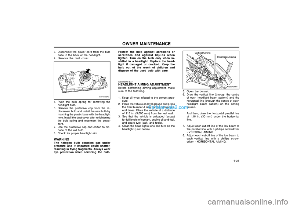
3. Disconnect the power cord from the bulb base in the back of the headlight.
4. Remove the dust cover.
5. Open the bonnet.
6. Draw the vertical line (through the centreof each headlight beam pattern) and the horizontal line (through the centre of eachheadlight beam pattern) on the aimingscreen. And then, draw the horizontal parallel line at 1.18 in. (30 mm) under the horizontalline.
7. Adjust each cut-off line of the low beam to the parallel line with a phillips screwdriver- VERTICAL AIMING
8. Adjust each cut-off line of the low beam to each vertical line with a phillips screw-driver - HORIZONTAL AIMING.
G290A01FC-EAT
HEADLIGHT AIMING ADJUSTMENT
Before performing aiming adjustment, makesure of the following.
1. Keep all tyres inflated to the correct pres- sure.
2. Place the vehicle on level ground and press the front bumper & rear bumper down sev-eral times. Place the vehicle at a distanceof 118 in. (3,000 mm) from the test wall.
3. See that the vehicle is unloaded (except for full levels of coolant, engine oil and fuel,and spare tyre, jack, and tools).
4. Clean the head lights lens and turn on the headlight (Low beam).
G290A01FC
Horizontal Aiming
Vertical Aiming
Protect the bulb against abrasions or scratches and against liquids whenlighted. Turn on the bulb only when in-stalled in a headlight. Replace the head-light if damaged or cracked. Keep thebulb out of the reach of children anddispose of the used bulb with care.
Page 141 of 407

CONSUMER INFORMATION 8-1
SI010B1-E
Engine Number
SI000A1-E
8. CONSUMER
INFORMATION
I010A01FC-EAT
VEHICLE IDENTIFICATION
NUMBER (VIN) The vehicle identification number (VIN) is
unique to each individual vehicle and is the number (sometimes referred to as chassisnumber) used upon the vehicle registrationdocument to identify the vehicle.
It can be found on the identification plate
attached to apron panel located on the driver'sside of the engine compartment. The engine number is stamped on the engine
block as shown in the drawing. I030A01FC-EAT
TYRE PRESSURES
In modern high-speed motoring, correct tyre
pressures are vitally important. Incorrect tyrepressures can affect vehicle safety by caus-ing reduced adhesion, steering response andtyre failure through overheating. The tyrepressure must only be checked when thetyres are cold. The correct tyre pressuresare indicated on the label affixed to the driver'sside "C" piller outer panel and below.
Diesel engine
I010B02B8
HFC6001
EADA010C
Petrol engine
5.5Jx14 5.5Jx15 6.0Jx15 3.5Jx153.5Jx15
TYRE
SIZE
RIM
SIZE PRESSURE, kPa (PSI)
185/65R14195/55R15 205/55R15
T115/70D15 T115/70R15 REAR
210(30)210(30)210(30)420(60)420(60) FRONT
250(36)250(36) 250(36) 420(60)420(60)
UP TO 2
PERSONS UP TO
MAX. LOAD
REAR
250(36)250(36) 250(36) 420(60)420(60)
FRONT210(30)210(30)210(30) 420(60) 420(60)
I030A01FC-D
Page 145 of 407

VEHICLE SPECIFICATIONS
9-2 DIESEL
1.5 4Cylinder in-line DOHC
740 ± 100- --
AUTO LASH
(1.6DOHC/Diesel)
AUTO LASH
(1.6DOHC/Diesel) -
1 - 3 - 2
PETROL
1.6/1.8 4Cylinder in-line DOHC
800 ± 100 (1.6L), 750 ± 100 (1.8L)800 ± 100 (1.6L), 800 ± 100 (1.8L)
BKR5ES-11RC10YC4
0.039 ~ 0.043 in. (1.0 ~ 1.1 mm)
0.0067 ~ 0.0091 in. (0.17 ~ 0.23 mm) (1.8DOHC)
0.0098 ~ 0.0122 in. (0.25 ~ 0.31 mm) (1.8 DOHC)
0.0047 ~ 0.011 in. (0.12 ~ 0.28 mm) (1.8 DOHC) 0.0079 ~ 0.015 in. (0.20 ~ 0.38 mm) (1.8 DOHC) BTDC 5° ± 5° (1.6L), BTDC 7° ± 5° (1.8L) 1 - 3 - 4 - 2
ITEMS
Engine Type Idle Speed (RPM) Spark Plug Spark Plug Gap Valve Clearance (Cold engine:20 ± 5°C) Ignition Timing Firing Order
A/CON OFF A/CON ON NGKCHAMPION
For adjusting
For checking
J070A03FC-EAT ENGINE
Intake
Exhaust
Intake
Exhaust
Page 147 of 407

INDEX10-1
A ACCESSORY TRAY
........................................................................ 1-50
AIR CONDITIONING SWITCH ........................................................ 1-60
AIR CONDITIONING SYSTEM MAINTENANCE ...........................6-18
AIR CLEANER ELEMENT REPLACEMENT ..................................6-12
ANTENNA ......................................................................................... 1-64
ANTI-THEFT ALARM SYSTEM .... .......................................... 1-5 ~ 1-7
AUTO FUEL CUT SWITCH ............................................................. 1-53
AUTOMATIC TRANSAXLE ............................................................... 2-6
AUTOMATIC TRANSAXLE FLUID ................................................ 6-14
B BATTERY MAINTENANCE ............................................................. 6-21
BEFORE STARTING THE ENGINE ................................................. 2-2
BLEEDING THE FUEL SYSTEM ....................................................6-23
BONNET RELEASE ......................................................................... 1-51
BRAKE PEDAL FREEPLAY .................................... ........................ 6-19
BRAKE TRACTION CONTROL SYSTEM ................... ................... 2-10
BRAKE SYSTEM CHECKING ........................................................ 6-16CCARE OF SEAT
BELTS ................................................................. 1-14
CARGO AREA COVER ................................................................... 1-53
CATALYTIC CONVERTOR OPERATING PRECAUTIONS ............. 7-1
CENTRE VENTILATOR ................................................................... 1-55
CENTRAL DOOR LOCKS ................................................................. 1-5
CHANGING A FLAT TYRE ............................................................... 3-4
CHECKING THE CLUTCH FLUID.................................................. 6-17
CHILD-PROOF REAR DOOR LOCK ................................................ 1-4
CHILD RESTRAINT SYSTEM ............................................. 1-17 ~ 1-22
CIGAR LIGHTER ............................................................................. 1-42
CLUTCH PEDAL FREEPLAY ......................................................... 6-19
COMBINATION IGNITION SWITCH AND STEERING LOCK ........ 2-2
COOLANT TEMPERATURE GAUGE .............................................1-35
D DAILY OPERATING CHECKS .......................................................... 6-4
DIGITAL CLOCK .............................................................................. 1-42
DOOR LOCKS ................................................................................... 1-3
DOOR WINDOWS ............................................................................. 1-7 DRINK HOLDER .............................................................................. 1-43
DRIVE BELTS .................................................................................. 6-20
DRIVING FOR ECONOMY ............................................................. 2-11
JK000A1-A 10. INDEX
10
Page 148 of 407

INDEX
10-2
E EFFECTIVE BRAKING
...................................................................... 2-9
ELECTRIC COOLING FANS ........................................................... 6-22
EMERGENCY TOWING ................... ...............................................3-10
EMISSION CONTROL SYSTEM ...................................................... 7-1
ENGINE COMPARTMENT ...................................................... 6-1 ~ 6-3
ENGINE COOLANT CHECKING AND REPLACING ....................... 6-9
ENGINE OIL AND FILTER REPLACEMENT ................................... 6-6
ENGINE OIL CONSUMPTION .......................................................... 6-6
ENGINE OIL REPLENISHMENT ...................................................... 6-5
ENGINE OIL ....................................................................................... 6-4
EXTERIOR REAR VIEW MIRR OR ................................................. 1-47
FFOLDING REAR SEATBACK AND SEAT CUSHION .......1-11 ~ 1-12
FOLD-UP TRAY ............................................................................... 1-50
FRONT ASHTRAY ........................................................................... 1-42
FRONT FOG LIGHT SWITCH ........................................................ 1-41
FUEL ECONOMY .............................................................................. 2-4
FUEL GAUGE .................................................................................. 1-35
FUEL RECOMMENDATIONS ........................................................... 1-1
FUSE PANEL DESCRIPTION ......................................................... 6-28
FUSIBLE LINKS ............................................................................... 6-20G GLOVE BOX
.................................................................................... 1-47
H HAZARD WARNING SYSTEM ........................................................ 1-40
HEADLIGHT AIMING ADJUSTEMENT ..........................................6-25
HEADLIGHT BULB ......................................................................... 6-24
HEADLIGHT LEVELING DEVICE SYSTEM ..................................1-44
HEAD RESTRAINT ADJUSTMENT ........................................ 1-9, 1-11
HEATED REAR WINDOW .............................................................. 1-41
HEATING CONTROL ....................................................................... 1-58
HEIGHT ADJUSTABLE FRONT SEAT SHOULDER BELT .......... 1-14
HORN ............................................................................................... 1-54
I
IF THE ENGINE CANNOT BE CRANKED ...................................... 3-1
IF THE ENGINE WILL NOT START ................................................ 3-1
IF THE EVENT OF A PUNCTURE ................................................... 3-4
IF YOUR VEHICLE MUST BE TOWED ........................................... 3-8
IMMOBILISER SYSTEM ......................................................... 1-2 ~ 1-3
INDIVIDUAL CIRCUIT FUSES ........................................................ 6-21
INSTRUMENT CLUSTER AND INDICATORS .............................. 1-30
INSTRUMENTS AND CONTROLS .................................................1-29
INTERIOR LIGHT ............................................................................ 1-46
INTERIOR REAR VIEW MIRROR .................................................. 1-49
Page 170 of 407

1FEATURES OF YOUR HYUNDAI
6
B880D02A-GAT Limp home procedures
The key number should be recorded and kept in a safe place in case theneed to order further keys arises. New keys are available from any Hyundai dealer by quoting the relevant keynumber. In the interest of security, the metal tag attached to the keys which bears thekey number should be removed from the key ring after you receive your new vehicle. In addition, key numbers can-not be provided by Hyundai for secu- rity reasons. If you need additional keys or if youshould lose your keys, your authorized Hyundai dealer can make new keys. In case the immobilizer warning indi-cator blinks for five seconds when the ignition key is turned to "ON" position,this indicates that the immobilizer sys- tem is out of order. And you cannot start the engine without the limp homeprocedures with ignition key. The following procedure is how to start the engine with the function of the limphome. (0, 1, 2, 3 as a sample pass- word).B880D01FCNOTE: You can get the limp home pass- word when the vehicle is first deliv- ered to you. If you do not have thepassword, consult your authorized Hyundai dealer.
1. To set the password you may turn
the ignition key "ON" and then turn it "OFF" according to the digit num-bers, then the immobilizer indicator will blink along with the operation of the ignition key. For example, turnthe ignition key once for digit num- ber "1", and twice for "2", and so on. However, for the digit number "0",you must turn the ignition key for 10 times.
2. Wait for 3~10 seconds.
3. You may set the remaining number of digits by following the same pro-cedures 1 and 2.
4. If all of four digits have been tried successfully, turn the ignition key"ON" and check that the immobi-lizer indicator illuminates. From this time, you have to start your engine within 30 seconds. If you start yourengine after 30 seconds, your en- gine will not start.