warning Hyundai Matrix 2005 Manual PDF
[x] Cancel search | Manufacturer: HYUNDAI, Model Year: 2005, Model line: Matrix, Model: Hyundai Matrix 2005Pages: 407, PDF Size: 10.31 MB
Page 131 of 407

OWNER MAINTENANCE
6-24 G270A02A-GAT HEADLIGHT BULB Replacement instructions:
G270A01FC
1. Allow the bulb to cool. Wear eye protection.
2. Always grasp the bulb by its plastic base, avoid touching the glass.
SG250A1-E
REPLACING LIGHT BULBS
In the event of bulb failure being experienced, ensure that the relative lighting circuit is turnedoff prior to attempting to replace the bulb. Theillustrations on the following page will assist inlocating and removing the various bulbs. En-sure that the replacement bulb has the samecap configuration and wattage as the original. CAUTION: Keep the lamps out of contact with petro- leum products, such as oil, petrol, etc.
1. Loosen the drain plug at the bottom of the
fuel filter.
2. Tighten the drain plug when water no longer comes out.
3. Check to be sure that the warning lamp illuminates when the ignition key is turnedto "ON", and that it goes off when theengine is started. If in doubt, consult your nearest Hyundai authorised repairer.
NOTE: It is recommended that water accumu- lated in the fuel filter should be removedby an authorized Hyundai authorised re-pairer. WARNING:
o Do not smoke or have any other open flame near the vehicle while bleeding the fuel system.
o Be sure to carefully wipe away any water drained out in this manner, be-cause the fuel mixed in the water mightbe ignited and result in a fire.
G300B02FC
If the fuel filter warning lamp illuminates during driving, it indicates that water has accumu-lated in the fuel filter. If this occurs, remove thewater as described.
G300A01B-GAT REMOVAL OF WATER FROM THE FUEL FILTER (Diesel engine)
G300A02FC
Page 132 of 407
OWNER MAINTENANCE 6-25
5. Push the bulb spring for removing the
headlight bulb.
6. Remove the protective cap from the re- placement bulb and install the new bulb by matching the plastic base with the headlighthole. Install the dust cover after retighteningthe bulb spring and reconnect the powercord.
7. Use the protective cap and carton to dis- pose of the old bulb.
8. Check for proper headlight aim.
WARNING The halogen bulb contains gas under
pressure and if impacted could shatter, resulting in flying fragments. Always weareye protection when servicing the bulb.
G270A02FC
3. Disconnect the power cord from the bulb base in the back of the headlight.
4. Remove the dust cover.
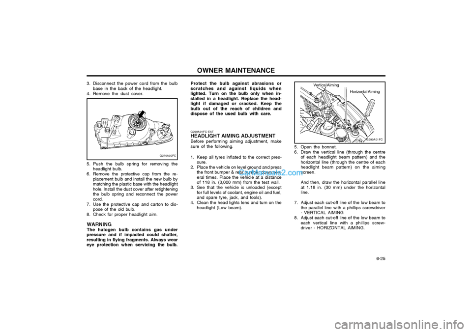
5. Open the bonnet.
6. Draw the vertical line (through the centreof each headlight beam pattern) and the horizontal line (through the centre of eachheadlight beam pattern) on the aimingscreen. And then, draw the horizontal parallel line at 1.18 in. (30 mm) under the horizontalline.
7. Adjust each cut-off line of the low beam to the parallel line with a phillips screwdriver- VERTICAL AIMING
8. Adjust each cut-off line of the low beam to each vertical line with a phillips screw-driver - HORIZONTAL AIMING.
G290A01FC-EAT
HEADLIGHT AIMING ADJUSTMENT
Before performing aiming adjustment, makesure of the following.
1. Keep all tyres inflated to the correct pres- sure.
2. Place the vehicle on level ground and press the front bumper & rear bumper down sev-eral times. Place the vehicle at a distanceof 118 in. (3,000 mm) from the test wall.
3. See that the vehicle is unloaded (except for full levels of coolant, engine oil and fuel,and spare tyre, jack, and tools).
4. Clean the head lights lens and turn on the headlight (Low beam).
G290A01FC
Horizontal Aiming
Vertical Aiming
Protect the bulb against abrasions or scratches and against liquids whenlighted. Turn on the bulb only when in-stalled in a headlight. Replace the head-light if damaged or cracked. Keep thebulb out of the reach of children anddispose of the used bulb with care.
Page 134 of 407
OWNER MAINTENANCE 6-27
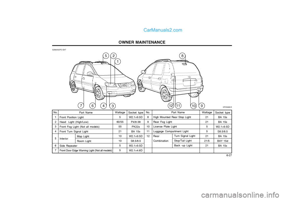
G280A02FC-EAT
HFC5006-D
58
461011129
2
1
3Socket typeW2.1×9.5D
P43t-38PK22s
BA 15s
W2.1×9.5D
S8.5/8.5
W2.1×9.5D W2.1×4.6D Part Name
High Mounted Rear Stop LightRear Fog Light License Plate Light Luggage Compartment Light Rear Combination
No.
12 3 4 5 6 7 Part Name
Front Position LightHead Light (High/Low) Front Fog Light (Not all models) Front Turn Signal Light InteriorSide Repeater Front Door Edge Warning Light (Not all models) No.
8 9
1011 12
Wattage
5
60/55 55 21 10 1055
Socket type BA 15s BA 15s
W2.1×9.5D
S8.5/8.5BA 15s
BAY 15d BA 15s
Map LightRoom Light
Turn Signal Light Stop/Tail Light Back -up Light
Wattage
21 2155
21
21/5 21
7
Page 143 of 407
CONSUMER INFORMATION 8-3
SI060B1-E
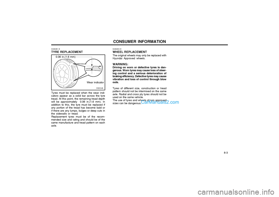
TYRE REPLACEMENT
Wear indicator
0.06 in.(1.6 mm)
HGK248SI060D2-E
WHEEL REPLACEMENT
The original wheels may only be replaced with
Hyundai Approved wheels.
WARNING: Driving on worn or defective tyres is dan-
gerous. Worn tyres may cause loss of steer- ing control and a serious deterioration ofbraking efficiency. Defective tyres may causevibration and loss of control through blowouts.
Tyres of different size, construction or tread
pattern should not be intermixed on the sameaxle. Radial and cross ply tyres should not beused on the same vehicle.
The use of tyres and wheels of non approved
sizes can be dangerous.
Tyres must be replaced when the wear indi-
cators appear as a solid bar across the tyretread. At this point, the remaining tread depthwill be approximately 0.06 in.(1.6 mm). Inaddition to this, the tyre must be replaced ifany portion of the tread has become bald orif there are any lumps, bulges or deep cuts inthe sidewalls or tread.
Replacement tyres must be of the recom-
mended size and rating and should be of thesame manufacture and tread pattern on eachaxle.
Page 148 of 407
INDEX
10-2
E EFFECTIVE BRAKING
...................................................................... 2-9
ELECTRIC COOLING FANS ........................................................... 6-22
EMERGENCY TOWING ................... ...............................................3-10
EMISSION CONTROL SYSTEM ...................................................... 7-1
ENGINE COMPARTMENT ...................................................... 6-1 ~ 6-3
ENGINE COOLANT CHECKING AND REPLACING ....................... 6-9
ENGINE OIL AND FILTER REPLACEMENT ................................... 6-6
ENGINE OIL CONSUMPTION .......................................................... 6-6
ENGINE OIL REPLENISHMENT ...................................................... 6-5
ENGINE OIL ....................................................................................... 6-4
EXTERIOR REAR VIEW MIRR OR ................................................. 1-47
FFOLDING REAR SEATBACK AND SEAT CUSHION .......1-11 ~ 1-12
FOLD-UP TRAY ............................................................................... 1-50
FRONT ASHTRAY ........................................................................... 1-42
FRONT FOG LIGHT SWITCH ........................................................ 1-41
FUEL ECONOMY .............................................................................. 2-4
FUEL GAUGE .................................................................................. 1-35
FUEL RECOMMENDATIONS ........................................................... 1-1
FUSE PANEL DESCRIPTION ......................................................... 6-28
FUSIBLE LINKS ............................................................................... 6-20G GLOVE BOX
.................................................................................... 1-47
H HAZARD WARNING SYSTEM ........................................................ 1-40
HEADLIGHT AIMING ADJUSTEMENT ..........................................6-25
HEADLIGHT BULB ......................................................................... 6-24
HEADLIGHT LEVELING DEVICE SYSTEM ..................................1-44
HEAD RESTRAINT ADJUSTMENT ........................................ 1-9, 1-11
HEATED REAR WINDOW .............................................................. 1-41
HEATING CONTROL ....................................................................... 1-58
HEIGHT ADJUSTABLE FRONT SEAT SHOULDER BELT .......... 1-14
HORN ............................................................................................... 1-54
I
IF THE ENGINE CANNOT BE CRANKED ...................................... 3-1
IF THE ENGINE WILL NOT START ................................................ 3-1
IF THE EVENT OF A PUNCTURE ................................................... 3-4
IF YOUR VEHICLE MUST BE TOWED ........................................... 3-8
IMMOBILISER SYSTEM ......................................................... 1-2 ~ 1-3
INDIVIDUAL CIRCUIT FUSES ........................................................ 6-21
INSTRUMENT CLUSTER AND INDICATORS .............................. 1-30
INSTRUMENTS AND CONTROLS .................................................1-29
INTERIOR LIGHT ............................................................................ 1-46
INTERIOR REAR VIEW MIRROR .................................................. 1-49
Page 149 of 407
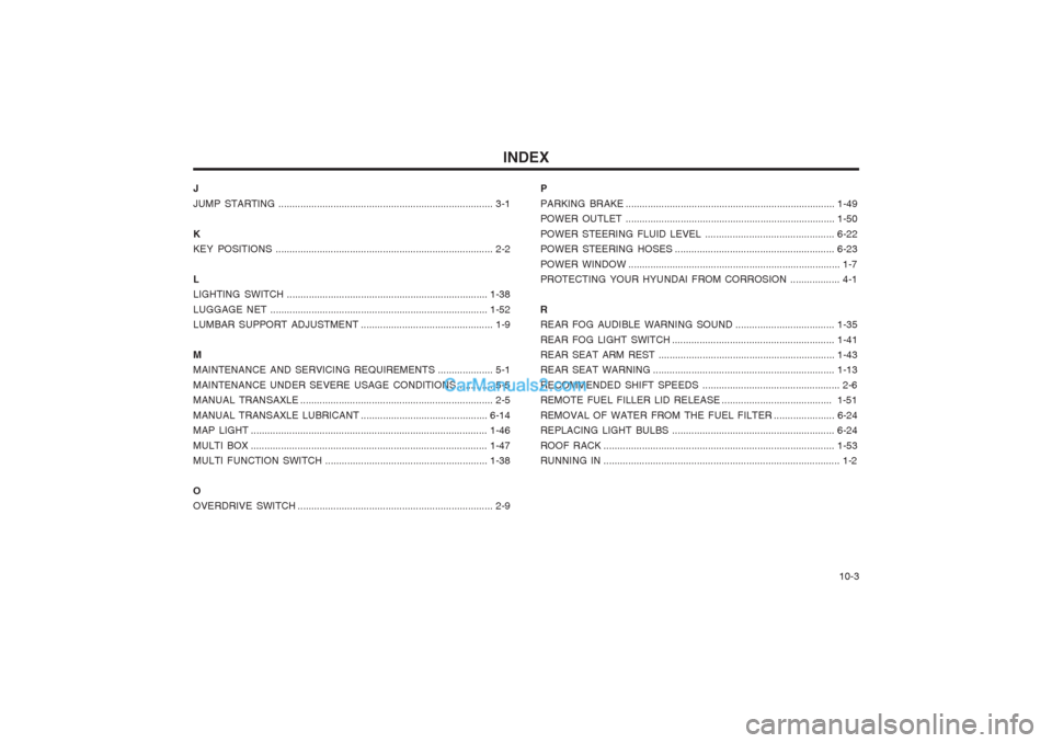
INDEX10-3
J JUMP STARTING
.............................................................................. 3-1
K KEY POSITIONS ............................................................................... 2-2
LLIGHTING SWITCH ......................................................................... 1-38
LUGGAGE NET ............................................................................... 1-52
LUMBAR SUPPORT ADJUSTMENT ................................................ 1-9
M
MAINTENANCE AND SERVICING REQUIREMENTS .................... 5-1
MAINTENANCE UNDER SEVERE USAGE CONDITIONS ............ 5-5
MANUAL TRANSAXLE ...................................................................... 2-5
MANUAL TRANSAXLE LUBRICANT ..............................................6-14
MAP LIGHT ...................................................................................... 1-46
MULTI BOX .............................. ........................................................ 1-47
MULTI FUNCTION SWITCH ........................................................... 1-38
OOVERDRIVE SWITCH ....................................................................... 2-9 P PARKING BRAKE
............................................................................ 1-49
POWER OUTLET ............................................................................ 1-50
POWER STEERING FLUID LEVEL ............................................... 6-22
POWER STEERING HOSES .......................................................... 6-23
POWER WINDOW ............................................................................. 1-7
PROTECTING YOUR HYUNDAI FROM CORROSION .................. 4-1
R
REAR FOG AUDIBLE WARNING SOUND ....................................1-35
REAR FOG LIGHT SWITCH ........................................................... 1-41
REAR SEAT ARM REST ................................................................ 1-43
REAR SEAT WARNING .................................................................. 1-13
RECOMMENDED SHIFT SPEEDS .................................................. 2-6
REMOTE FUEL FILLER LID RELEASE ........................................ 1-51
REMOVAL OF WATER FROM THE FUEL FILTER ...................... 6-24
REPLACING LIGHT BULBS ........................................................... 6-24
ROOF RACK .................................................................................... 1-53
RUNNING IN ...................................................................................... 1-2
Page 158 of 407
!
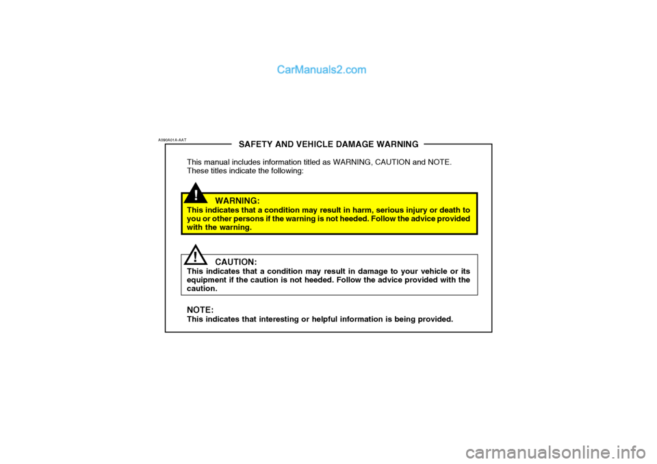
SAFETY AND VEHICLE DAMAGE WARNING
This manual includes information titled as WARNING, CAUTION and NOTE. These titles indicate the following:
WARNING:
This indicates that a condition may result in harm, serious injury or death to you or other persons if the warning is not heeded. Follow the advice provided with the warning.
CAUTION:
This indicates that a condition may result in damage to your vehicle or its equipment if the caution is not heeded. Follow the advice provided with the caution. NOTE: This indicates that interesting or helpful information is being provided.
A090A01A-AAT
!
Page 161 of 407
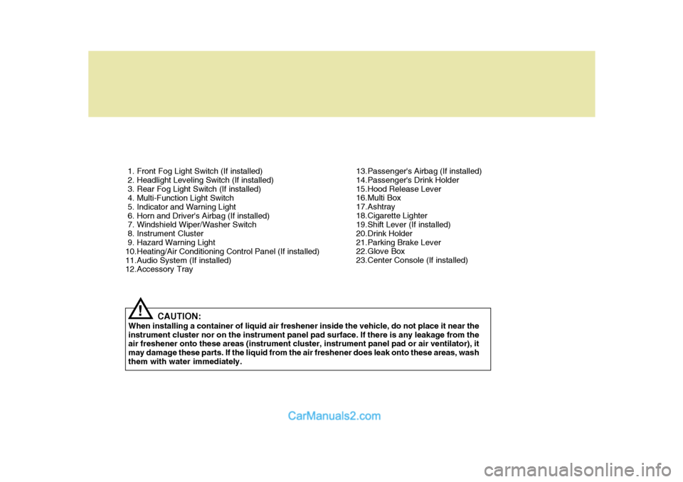
1. Front Fog Light Switch (If installed)
2. Headlight Leveling Switch (If installed)
3. Rear Fog Light Switch (If installed)
4. Multi-Function Light Switch
5. Indicator and Warning Light
6. Horn and Driver's Airbag (If installed)
7. Windshield Wiper/Washer Switch
8. Instrument Cluster
9. Hazard Warning Light
10.Heating/Air Conditioning Control Panel (If installed)
11.Audio System (If installed)
12.Accessory TrayCAUTION:
When installing a container of liquid air freshener inside the vehicle, do not place it near the instrument cluster nor on the instrument panel pad surface. If there is any leakage from the air freshener onto these areas (instrument cluster, instrument panel pad or air ventilator), it may damage these parts. If the liquid from the air freshener does leak onto these areas, washthem with water immediately.
! 13.Passenger's Airbag (If installed)
14.Passenger's Drink Holder
15.Hood Release Lever
16.Multi Box
17.Ashtray
18.Cigarette Lighter
19.Shift Lever (If installed)
20.Drink Holder
21.Parking Brake Lever
22.Glove Box
23.Center Console (If installed)
Page 163 of 407
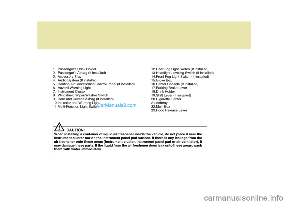
1. Passenger's Drink Holder
2. Passenger's Airbag (If installed)
3. Accessory Tray
4. Audio System (If installed)
5. Heating/Air Conditioning Control Panel (If installed)
6. Hazard Warning Light
7. Instrument Cluster
8. Windshield Wiper/Washer Switch
9. Horn and Driver's Airbag (If installed)
10.Indicator and Warning Light
11.Multi-Function Light SwitchCAUTION:
When installing a container of liquid air freshener inside the vehicle, do not place it near theinstrument cluster nor on the instrument panel pad surface. If there is any leakage from the air freshener onto these areas (instrument cluster, instrument panel pad or air ventilator), itmay damage these parts. If the liquid from the air freshener does leak onto these areas, wash them with water immediately.
! 12.Rear Fog Light Switch (If installed)
13.Headlight Leveling Switch (If installed)
14.Front Fog Light Switch (If installed)
15.Glove Box
16.Center Console (If installed)
17.Parking Brake Lever
18.Drink Holder
19.Shift Lever (If installed)
20.Cigarette Lighter
21.Ashtray
22.Multi Box
23.Hood Release Lever
Page 164 of 407
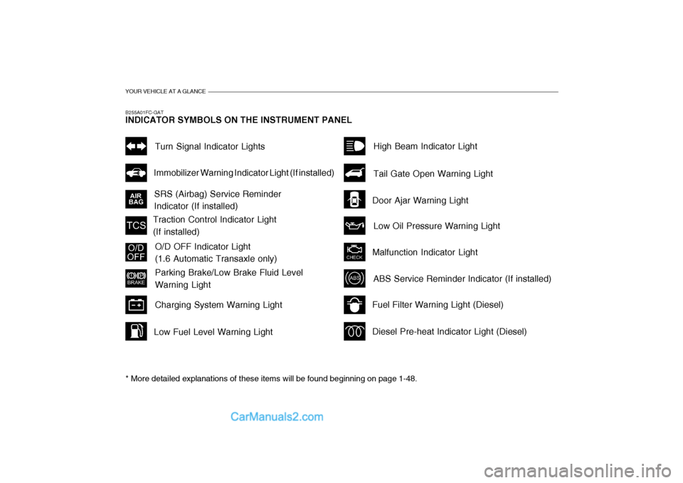
YOUR VEHICLE AT A GLANCE
B255A01FC-GAT INDICATOR SYMBOLS ON THE INSTRUMENT PANEL * More detailed explanations of these items will be found beginning on page 1-48.
SRS (Airbag) Service Reminder Indicator (If installed)Turn Signal Indicator Lights
Malfunction Indicator Light
Traction Control Indicator Light(If installed)
O/D OFF Indicator Light (1.6 Automatic Transaxle only)
Parking Brake/Low Brake Fluid Level Warning Light
Charging System Warning Light
Fuel Filter Warning Light (Diesel) Diesel Pre-heat Indicator Light (Diesel)
Immobilizer Warning Indicator Light (If installed)
ABS Service Reminder Indicator (If installed) High Beam Indicator Light Low Oil Pressure Warning Light
Tail Gate Open Warning Light
Door Ajar Warning Light
Low Fuel Level Warning Light