warning Hyundai Matrix 2005 Workshop Manual
[x] Cancel search | Manufacturer: HYUNDAI, Model Year: 2005, Model line: Matrix, Model: Hyundai Matrix 2005Pages: 407, PDF Size: 10.31 MB
Page 85 of 407
DRIVING YOUR HYUNDAI 2- 13
NOTE: Never allow undiluted screen washer fluidadditive to spill upon the paintwork or use engine coolant anti-freeze since damage to the paintwork may result.
o When driving in extreme conditions, the
windscreen wiper blades may fail to clear the screen properly due to the formation of ice upon the blade edge. It will therefore be necessary to periodically remove such ice to restore their efficiency.
o If the power operated door mirrors become frozen, attempts to adjust these may dam-age the mechanism.
o The formation of snow or ice built up inside the wheel arches may interfere with theroad wheels or steering mechanism. In such instances, unusual noises or an in- crease in steering effort may result. There- fore, ensure that the wheel arches are checked periodically and any accumulated snow or ice removed.
o It is advisable to carry emergency equip- ment including, torch, shovel, tow rope,blankets etc., if a journey is to be under- taken into areas of severe road conditions. SC200B3-E
TOWING ATTACHMENTS It is strongly recommended that only an
Hyundai Approved towing attachment is usedto ensure that the loads placed upon the body structure are correctly distributed. The use of a non approved attachment will result in the invalidation of the vehicle warranty. Hyundai towing attachments are designed and con- structed to ensure maximum towing perfor- mance and ease of fitment. A range of acces- sories including electrical kits are available through the Hyundai authorised repairer net- work.
It is of the utmost importance that those areas
of the vehicle which are subjected to greaterstress during towing are maintained in accor- dance with the recommendations given at the end of this book. In addition, the daily operating checks relating to engine oil, transmission oil and tyres must be performed at each refuelling to ensure maximum reliability and safety. The use of a proprietary stabiliser will assist in
achieving an inherently stable outfit but whilstthe use of such equipment will improve the characteristics of a balanced outfit, it will not compensate for a badly loaded and therefore unstable outfit.
The tyres and braking equipment fitted to the
trailer or caravan must be maintained in ac- cordance with the recommendations of the manufacturer. Special attention should be paid
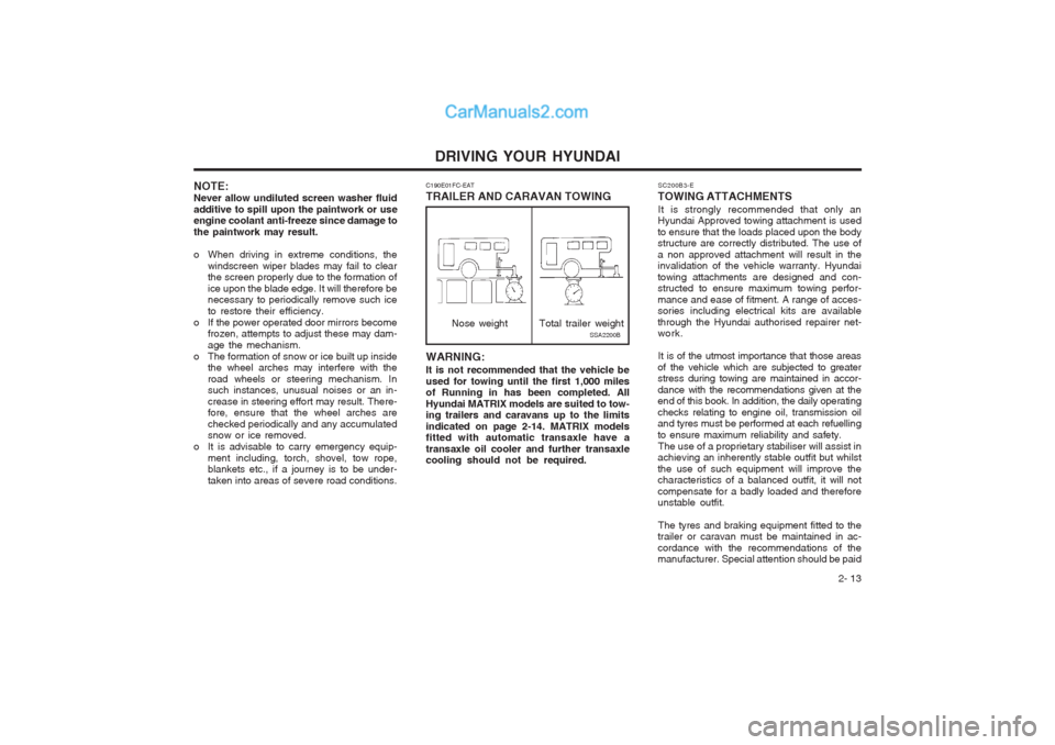
WARNING: It is not recommended that the vehicle be used for towing until the first 1,000 miles of Running in has been completed. All Hyundai MATRIX models are suited to tow- ing trailers and caravans up to the limits indicated on page 2-14. MATRIX models fitted with automatic transaxle have a transaxle oil cooler and further transaxle cooling should not be required.
C190E01FC-EAT TRAILER AND CARAVAN TOWING
Nose weightSSA2200B
Total trailer weight
Page 88 of 407
3-1
IN CASE OF EMERGENCY
SD000A1-E
3. IN CASE OF EMERGENCY
SD020A1-E IF THE ENGINE WILL NOT START Seek assistance from the nearest Hyundai authorised repairer with regard to the method of ignition and fuel system diagnosis. CAUTION: If the engine refuses to start, no attemptshould be made to push or tow start the vehicle. Vehicles with automatic transaxle or fuel injection will not be able to be started in this manner since no drive is transmitted through the automatic transaxle whilst the engine is not running, and in the case of fuel injected derivatives, the fuel pump will not operate under tow start con- ditions. In addition, if the vehicle is equipped with an exhaust catalyst, dam- age to the catalyst may result if the vehicle is tow started. SD020B1-E
If the Engine Cannot be Cranked
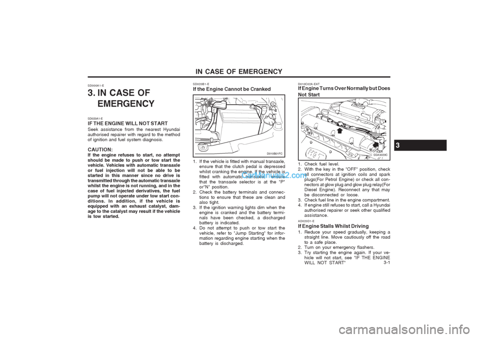
D010C02A-EAT If Engine Turns Over Normally but Does Not Start
SSA3020C
1. Check fuel level.
2. With the key in the "OFF" position, check all connectors at ignition coils and spark plugs(For Petrol Engine) or check all con- nectors at glow plug and glow plug relay(For Diesel Engine). Reconnect any that may be disconnected or loose.
3. Check fuel line in the engine compartment.
4. If engine still refuses to start, call a Hyundai authorised repairer or seek other qualifiedassistance.
1. If the vehicle is fitted with manual transaxle,
ensure that the clutch pedal is depressed whilst cranking the engine. If the vehicle is fitted with automatic transaxle, ensure that the transaxle selector is at the "P" or"N" position.
2. Check the battery terminals and connec-
tions to ensure that these are clean andalso tight.
3. If the ignition warning lights dim when the engine is cranked and the battery termi- nals have been checked, a discharged battery is indicated.
4. Do not attempt to push or tow start the vehicle, refer to "Jump Starting" for infor-mation regarding engine starting when the battery is discharged. AD020D1-E
If Engine Stalls Whilst Driving
1. Reduce your speed gradually, keeping a straight line. Move cautiously off the road to a safe place.
2. Turn on your emergency flashers.
3. Try starting the engine again. If your ve-
hicle will not start, see "IF THE ENGINE WILL NOT START"
3
D010B01FC
Page 89 of 407
IN CASE OF EMERGENCY
3-2
CAUTION: Personal injury and damage to the vehicle may occur if jump starting is not per- formed correctly. If any doubt exists as to how this operation should be performed, seek assistance from qualified personnel. WARNING: Motor vehicle batteries contain sulphuric acid and emit hydrogen gas. Protective clothing should be worn and care exer- cised to prevent the acid from coming into contact with skin or clothing and the ve- hicle. Naked lights should not be permitted in the vicinity of the battery. Care should be exercised to prevent sparks occurring during connection. If acid accidentally comes into contact with skin or eyes, the affected area should immediately be flushed CAUTION: If the jump cable are incorrectly installed,
damage to the vehicle electrical system may occur, in particular the electronic components such as the Fuel Injection system computer and the Automatic
Transaxle computer. The battery must never be disconnected whilst the engine is running. SD040A2-E IF THE ENGINE OVERHEATS
If the temperature gauge indicates overheat- ing:
1. Pull off the road and stop as soon as it is safe to do so.
2. Place the gear selector lever in "P" (auto- matic), or neutral (manual transaxle) and set the parking brake. If the air condition- ing is on, turn it off.
3. If coolant is running out under the car or
steam is coming out from under the bonnet stop the engine. Do not open the bonnet until the coolant has stopped running or the steaming has stopped. If there is no visible loss of coolant and no steam, leave the engine running and check to be sure the engine cooling fan is operating.If the fan is not running, turn the engine off.
4. Check to see if the water pump drive belt is broken. If it is not missing, check to seethat it is tight.
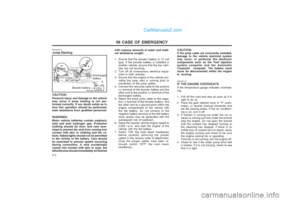
SD030A2-E Jump Starting
with copious amounts of water and medi- cal assistance sought.
1. Ensure that the booster battery is 12 volt
type. If the booster battery is installed in another vehicle, ensure that the two vehi- cles are not touching.
2. Turn off all unnecessary electrical equip- ment in both vehicles.
3. Ensure that the engine of the vehicle pro- viding the jump start is running prior to connection of the jump cables.
4. Connect the red jump cable to the positive (+) terminal of the booster battery and theother end to the positive (+) terminal of the discharged battery.
5. Attach the black jump cable to the nega- tive (-) terminal of the booster battery, andthe other end to a ground point within the engine compartment of the vehicle with the flat battery. Do not connect to the negative battery terminal of the flat battery since sparks may be generated with the subsequent risk of explosion.
6. Raise the booster vehicle engine speed to 2,000 r.p.m. and start the engine of thevehicle with the flat battery.
7. Switch "ON" the main beam headlamps before carefully removing the jumper cables in the reverse order of attachment. Once the jumper cables have been re- moved, switch "OFF" the main beam headlamps.
HFC4002
Booster battery Discharged battery
Page 90 of 407
3-3
IN CASE OF EMERGENCY
If the drive belt seems to be satisfactory, check for coolant leaking from the radiator, hoses or under the car. (If the air condi- tioning had been in use, it is normal for cold water to be draining from it).
WARNING: Whilst the engine is running, keep hands and clothing away from moving parts such as the fan and drive belts to prevent injury. WARNING (Diesel only): Never work on injection system with en-gine running or within 30 seconds after shutting off engine. High pressure pump, rail, injectors and high pressure pipes are subject to high pressure even after the engine stopped. The fuel jet produced by fuel leaks may cause serious injury, if it touch the body. People using pacemak- ers should ensure that they keep a dis- tance of 30cm from the ECU or wiring harness within the engine room whilst engine is running, since the high currents in the Common Rail system produce con- siderable magnetic fields.
5. If the water pump drive belt is broken or coolant is leaking out, stop the engine immediately and call the nearest Hyundai authorised repairer for assistance. WARNING:Do not remove the radiator cap when theengine is hot since steam and boiling water may be ejected from the radiator resulting in burns or scalding.
6. If the cause of the overheating cannot be found, wait until the engine temperature has returned to normal. Then, if coolant has been lost, carefully remove the radia- tor cap and add water to bring the fluid level in the reservoir up to the base of the radiator fill opening. Fill the coolant expan- sion tank to the halfway mark.
7. Proceed with caution until it is established that the engine is operating normally. If theengine overheats repeatedly, the advice of a Hyundai authorised repairer should be sought.
CAUTION:Serious loss of coolant indicates there is a leak in the cooling system and this should be checked as soon as possible by a Hyundai authorised repairer. D040A01FC-EAT
TEMPORARY SPARE TYRE The following instructions for the temporary
spare tyre should be observed:
1. Check inflation pressure as soon as pos-
sible after installing the spare tyre, and adjust to the specified pressure. The tyre pressure should be periodically checked and maintained at the specified pressure whilst the tyre is stored.
2. The spare tyre should only be used tem- porarily and should be returned to the luggage compartment as soon as the origi- nal tyre can be repaired or replaced.
3. Continuous use at speeds of over 80 km/h
(50 mph) is not recommended.
4. As the temporary spare tyre is specifically designed for your car, it should not beused on any other vehicle.
5. The temporary spare tyre should not be used on any other wheels, nor shouldstandard tyre, snow tyre, wheel covers or trim rings be used with the temporary spare wheel. If such use is attempted, damage to these items or other car com- ponents may occur.
6. The temporary spare tyre pressure should be checked once a month whilst the tyreis stored.
Spare Tyre Pressure
Type Size Inflation Pressure T115/70R(D)15420 kPa (60 psi)
Page 93 of 407

IN CASE OF EMERGENCY
3-6 SD070G1-E
5. Raising the Car
After inserting a wrench bar into the wheel nut
wrench, install the wrench bar into the jack as shown in the drawing. To raise the vehicle, turn the wheel nut wrench clockwise. As the jack begins to raise the vehicle, double check that it is properly positioned and will not slip. If the jack is on soft ground or sand, it may be necessary to place a stout piece of timber under the base of the jack to prevent it from sinking.
Raise the car high enough so that the fully
inflated spare wheel can be installed.
WARNING: Do not get under the car when it is support-
ed by the jack! The jack is solely designedfor wheel changing and is not intended to support the vehicle for other purposes. The use of purpose designed supports is neces- sary whilst the vehicle is raised and the operator is required to get underneath.
HFC4022
Wrench bar
Wheel nut wrench
SD070E1-E 3. Loosen Wheel Nuts The wheel nuts should be loosened slightly before raising the car. To loosen the nuts, turn the wheel brace counterclockwise. Ensure that the wheel brace socket is seated properly on the nut and that it cannot slip. Do not remove the nuts at this stage. SD070F1-F
4. Put the Jack in Place
The base of the jack should be placed on firm,level ground. The jack should be positioned as shown in the drawing.
D060D01FC-DHFC4006
Page 94 of 407

3-7
IN CASE OF EMERGENCY
WARNING: It is important that the faces of the wheeland hub are clean prior to installing the wheel. The prescence of dirt or other mat- ter in the wheel or hub faces could result in the wheel nuts becoming loose whilst the vehicle is being driven. SD070I1-E
7. Re-install Wheel Nuts
Fit the wheel nuts onto the studs and tighten with the wheel brace.
SD070H1-E 6. Changing Wheels Using the wheel brace, remove the nuts and slide the wheel off the hub and wheel studs. Lie the wheel flat to prevent it from rolling. Ensure that the faces of the wheel and hub are clean. Position the spare wheel over the studs and slide it up to the hub.
STA3071H
D060H01FC-D
D060G01FC
SD070J1-E
8. Lower Vehicle and Tighten Nuts
Lower the car to the ground turning the wheel
nut wrench counterclockwise. When the ve- hicle is firmly on the ground, remove the jack and tighten the wheel nuts securely. At the first available opportunity, the wheel nut torque should be checked with a suitable torque wrench.
Wheel nut tightening torqueSteel wheel & aluminium alloy wheel: 90-110 Nm (65-80 lb.ft)
D060I01FC-D
Page 105 of 407
VEHICLE MAINTENANCE REQUIREMENTS
5- 6 6ZF060D2-A
o Fuel lines, Fuel Hoses and
Connections
Check the fuel lines, fuel hoses and connec- tions for leakage and damage. Replace anydamaged or leaking parts immediately.
WARNING (Diesel only): Never work on injection system with en-gine running or within 30 seconds aftershutting off engine. High pressure pump,rail, injectors and high pressure pipes aresubject to high pressure even after theengine stopped. The fuel jet produced byfuel leaks may cause serious injury, if itcontacts the body. People using pace-makers should ensure that they keep adistance of 30cm from the ECU or wiringharness within the engine room whilstengine is running, since the high currentsin the Common Rail system produce con-siderable magnetic fields. 6ZF060E1-A
o Timing Belt Replace timimg belt and inspect all associated parts related for damage and deformation.Replace any damaged parts immediately. 6ZF060G1-A
o Vapour Hose and Fuel Filler Cap The vapour hose and fuel filler cap should be inspected at those intervals specified in themaintenance schedule. Make sure that a newvapour hose or fuel filler cap is correctlyreplaced. 6ZF060F1-A
o Vacuum, Crankcase
Ventilation Hoses
Inspect the surface of hoses for evidence of heat and/or mechanical damage. Hard andbrittle rubber, cracking, tears, cuts, abra-sions, and excessive swelling indicate dete-rioration. Particular attention should be paid toexamining those hose surfaces nearest tohigh heat sources, such as the exhaustmanifold.Inspect the hose routing to assure that thehoses do not come in contact with any heatsource, sharp edges or moving componentwhich might cause heat damage or mechani-cal wear. Inspect all hose connections, suchas clamps and couplings, to make sure theyare secure, and that no leaks are present.Hoses should be replaced immediately if thereis any evidence of deterioration or damage.
6ZF060A1-A
EXPLANATION OF SCHEDULED MAINTENANCE ITEMS
6ZF060M1-A
o Engine Oil and Filter The engine oil and filter should be changed at
the intervals specified in the maintenance schedule. If the car is being driven in severeconditions, more frequent oil and filter changesare required.
6ZF060B1-A
o Drive Belts Inspect all drive belts for evidence of cuts,
cracks, excessive wear or oil contaminationand replace if necessary. Drive belts shouldbe checked periodically for proper tensionand adjusted as necessary.
6ZF060C1-A
o Fuel Filter A clogged filter can limit the speed at which the
vehicle may be driven, damage the emissionsystem and cause hard starting. If an exces-sive amount of foreign matter accumulates inthe fuel tank, the filter may require replace-ment more frequently.
After installing a new filter, run the engine for
several minutes, and check for leaks at theconnections.
Page 111 of 407
OWNER MAINTENANCE
6-4 SG020B1-E
DAILY OPERATING CHECKS
The following items should be checked on a
daily basis or whenever the vehicle is refuelled, whichever occurs sooner.
o Engine oil level.
o Engine coolant level.
o Power steering fluid level.
o Brake fluid level.
o Windscreen washer fluid level.
o Battery condition.
o Tyre condition and pressures.
o Operation and cleanliness of all lighting equipment.
o Windscreen wiper and washer operation.
o Horn operation.
o Warning light operation.
o Adjustment and cleanliness of mirrors.
o Seat and seat belt adjustment and opera- tion.
o Fluid leakage.
The vehicle must not be driven if the daily
operating checks indicate that any item of equip- ment related to the safety or roadworthiness ofthe vehicle is not functioning correctly. G030A01FC-EAT
ENGINE OIL
The correct engine oil level is of paramount
importance. An excessively high or low oil levelmay result in irreparable damage being sus-tained by the engine. The engine oil levelmust be checked on a daily basis, wheneverthe vehicle is refuelled or before starting along trip, whichever occurs sooner.
In addition, it is imperative that only an ap-
proved grade and specification of oil is used toavoid the possibility of serious engine damageand premature wear. The use of "budget price"oil is a false economy that must be avoided ifthe maximum reliability and useful life is to beobtained from the vehicle. G030B02O-EAT
Recommended Oil
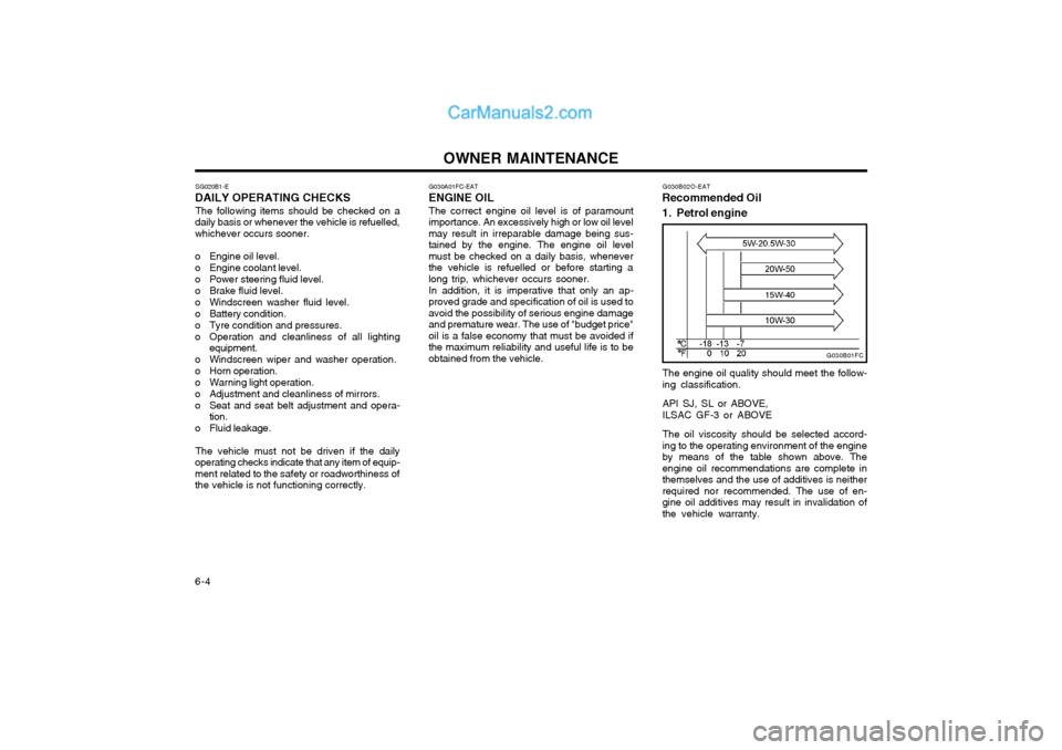
1. Petrol engine
G030B01FC
The engine oil quality should meet the follow- ing classification. API SJ, SL or ABOVE, ILSAC GF-3 or ABOVE The oil viscosity should be selected accord- ing to the operating environment of the engineby means of the table shown above. Theengine oil recommendations are complete inthemselves and the use of additives is neitherrequired nor recommended. The use of en-gine oil additives may result in invalidation ofthe vehicle warranty.
Page 113 of 407
OWNER MAINTENANCE
6-6 ZG030E1-A
ENGINE OIL CONSUMPTION Function of engine oil
Engine oil has the primary function of lubricat- ing and cooling the inside of the engine.
Engine oil consumption It is normal that an engine should consumesome engine oil in the course of normaldriving. The cause of oil consumption in anormal engine are as follows;
o Engine oil is used to lubricate pistons, piston rings and cylinders. A thin film of oil is left on the cylinder wall when a piston moves downwards in thecylinder. High negative pressure generatedduring engine operation sucks some of theoil into the combustion chamber.This oil with some oil of the cylinder wall isburned by the high temperature combustiongases during the combustion process.
o The engine oil consumption is strongly effected by the viscosity and quality of oil,engine rpm and driving condition etc. More engine oil may be consumed under severe driving conditions such as highspeeds, frequent acceleration and decel-eration, compared to normal driving.
If the indicated oil level is at or below the lower
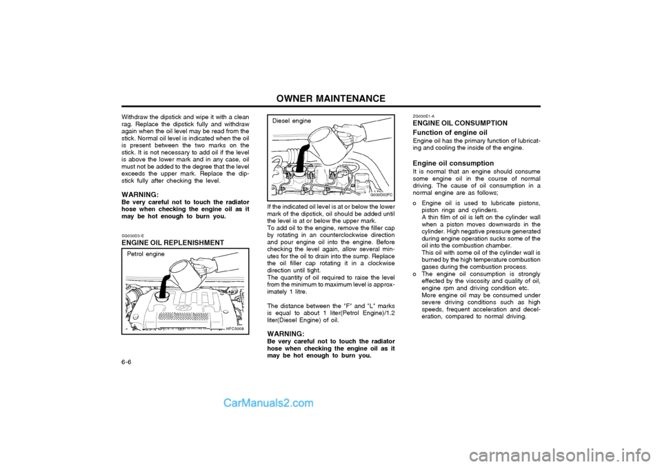
mark of the dipstick, oil should be added untilthe level is at or below the upper mark. To add oil to the engine, remove the filler cap
by rotating in an counterclockwise directionand pour engine oil into the engine. Beforechecking the level again, allow several min-utes for the oil to drain into the sump. Replacethe oil filler cap rotating it in a clockwisedirection until tight.
The quantity of oil required to raise the level
from the minimum to maximum level is approx-imately 1 litre.
The distance between the "F" and "L" marks
is equal to about 1 liter(Petrol Engine)/1.2liter(Diesel Engine) of oil.
WARNING: Be very careful not to touch the radiator
hose when checking the engine oil as it may be hot enough to burn you.
G030D02FC
Diesel engine
SG030D3-E
ENGINE OIL REPLENISHMENT
HFC5009
Petrol engine
Withdraw the dipstick and wipe it with a clean rag. Replace the dipstick fully and withdrawagain when the oil level may be read from thestick. Normal oil level is indicated when the oilis present between the two marks on thestick. It is not necessary to add oil if the levelis above the lower mark and in any case, oilmust not be added to the degree that the levelexceeds the upper mark. Replace the dip-stick fully after checking the level. WARNING: Be very careful not to touch the radiator hose when checking the engine oil as itmay be hot enough to burn you.
Page 114 of 407
OWNER MAINTENANCE 6-7
SG040A2-E
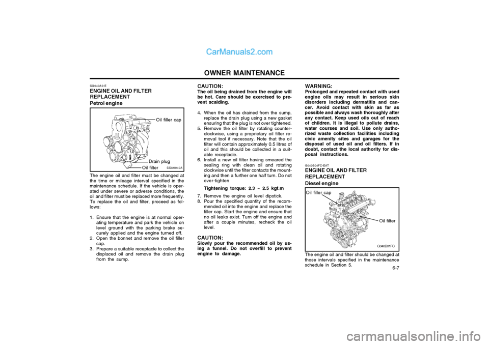
ENGINE OIL AND FILTER
REPLACEMENT
Petrol engine
SSA6040A
Oil filler cap
Drain plug
Oil filter
The engine oil and filter must be changed at
the time or mileage interval specified in the maintenance schedule. If the vehicle is oper-ated under severe or adverse conditions, theoil and filter must be replaced more frequently.
To replace the oil and filter, proceed as fol-
lows:
1. Ensure that the engine is at normal oper- ating temperature and park the vehicle on level ground with the parking brake se-curely applied and the engine turned off.
2. Open the bonnet and remove the oil filler cap.
3. Prepare a suitable receptacle to collect the displaced oil and remove the drain plugfrom the sump. CAUTION: The oil being drained from the engine will
be hot. Care should be exercised to pre- vent scalding.
4. When the oil has drained from the sump, replace the drain plug using a new gasket ensuring that the plug is not over tightened.
5. Remove the oil filter by rotating counter- clockwise, using a proprietary oil filter re-moval tool if necessary. Note that the oilfilter will contain approximately 0.5 litres ofoil and this should be collected in a suit-able receptacle.
6. Install a new oil filter having smeared the sealing ring with clean oil and rotatingclockwise until the filter contacts the mount-ing and then a further one half turn. Do notover-tighten Tightening torque: 2.3 ~ 2.5 kgf.m
7. Remove the engine oil level dipstick.
8. Pour the specified quantity of the recom- mended oil into the engine and replace the filler cap. Start the engine and ensure thatno oil leaks exist. Turn off the engine andafter a couple minutes, recheck the oillevel.
CAUTION: Slowly pour the recommended oil by us-
ing a funnel. Do not overfill to prevent engine to damage. WARNING: Prolonged and repeated contact with used
engine oils may result in serious skin disorders including dermatitis and can-cer. Avoid contact with skin as far aspossible and always wash thoroughly afterany contact. Keep used oils out of reachof children. It is illegal to pollute drains,water courses and soil. Use only autho-rized waste collection facilities includingcivic amenity sites and garages for thedisposal of used oil and oil filters. If indoubt, contact the local authority for dis-posal instructions.
G040B01FC
G040B04FC-EAT
ENGINE OIL AND FILTER REPLACEMENT Diesel engine
Oil filter
Oil filler cap
The engine oil and filter should be changed at
those intervals specified in the maintenance schedule in Section 5.