sensor HYUNDAI NEXO 2023 Manual PDF
[x] Cancel search | Manufacturer: HYUNDAI, Model Year: 2023, Model line: NEXO, Model: HYUNDAI NEXO 2023Pages: 558, PDF Size: 35.01 MB
Page 475 of 558
7-51
7
Maintenance
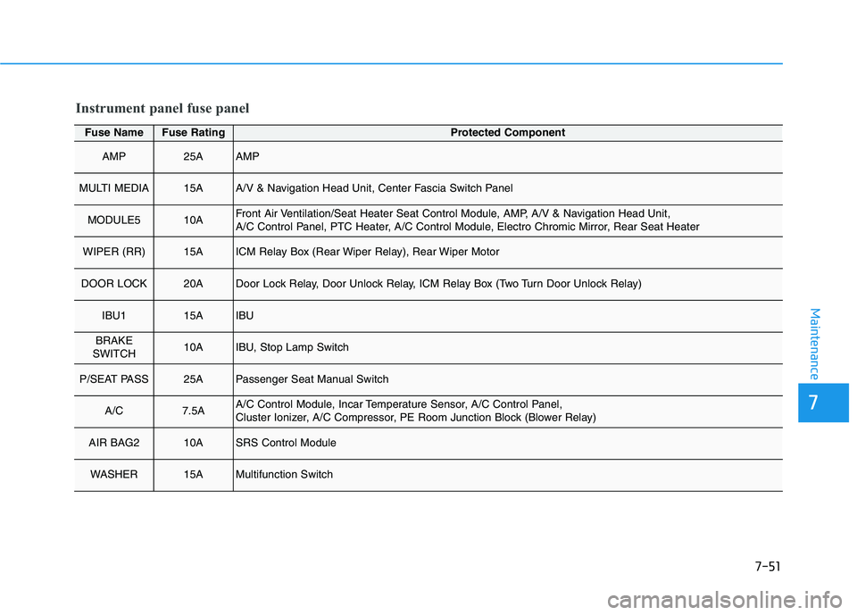
Fuse NameFuse RatingProtected Component
AMP25AAMP
MULTI MEDIA15AA/V & Navigation Head Unit, Center Fascia Switch Panel
MODULE510AFront Air Ventilation/Seat Heater Seat Control Module, AMP, A/V & Navigation Head Unit,
A/C Control Panel, PTC Heater, A/C Control Module, Electro Chromic Mirror, Rear Seat Heater
WIPER (RR)15AICM Relay Box (Rear Wiper Relay), Rear Wiper Motor
DOOR LOCK20ADoor Lock Relay, Door Unlock Relay, ICM Relay Box (Two Turn Door Unlock Relay)
IBU115AIBU
BRAKE
SWITCH10AIBU, Stop Lamp Switch
P/SEAT PASS25APassenger Seat Manual Switch
A/C7.5AA/C Control Module, Incar Temperature Sensor, A/C Control Panel,
Cluster Ionizer, A/C Compressor, PE Room Junction Block (Blower Relay)
AIR BAG210ASRS Control Module
WASHER15AMultifunction Switch
Instrument panel fuse panel
Page 476 of 558
7-52
Maintenance
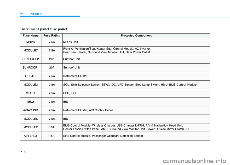
Fuse NameFuse RatingProtected Component
MDPS7.5AMDPS Unit
MODULE77.5AFront Air Ventilation/Seat Heater Seat Control Module, AC Inverter,
Rear Seat Heater, Surround View Monitor Unit, Rear Power Outlet
SUNROOF220ASunroof Unit
SUNROOF120ASunroof Unit
CLUSTER7.5AInstrument Cluster
MODULE37.5ASCU, Shift Selection Switch (SBW), IDC, VPD Sensor, Stop Lamp Switch, HMU, BMS Control Module
START7.5AFCU, IBU
IBU27.5AIBU
A/BAG IND7.5AInstrument Cluster, A/C Control Panel
MODULE67.5AIBU
MODULE210ABMS Control Module, Wireless Charger, USB Charger LH/RH, A/V & Navigation Head Unit,
Center Fascia Switch Panel, AMP, Surround View Monitor Unit, Power Outside Mirror Switch, IBU
AIR BAG115ASRS Control Module, Passenger Occupant Detection Sensor
Instrument panel fuse panel
Page 486 of 558
7-62
MaintenanceA
A PPPPEEAA RRAA NN CCEE CC AA RREE
Exterior Care
Exterior general caution
It is very important to follow the label
directions when using any chemical
cleaner or polish. Read all warningand caution statements that appearon the label.
High-pressure washing
When using high-pressure wash-
ers, make sure to maintain suffi-
cient distance from the vehicle.
Insufficient clearance or excessivepressure can lead to component
damage or water penetration.
Do not spray the camera, sensors or its surrounding area directly with
a high pressure washer. Shock
applied from high pressure water
may cause the device to not oper-
ate normally.
Do not bring the nozzle tip close to boots (rubber or plastic covers)or
connectors as they may be dam-
aged if they come into contact with
high pressure water.
Do not use any high-pressure noz- zles, which induce either one-direct
water stream or water swirling.
Protecting your vehicle’s finish
Washing
To help protect your vehicle’s finish
from rust and deterioration, wash itthoroughly and frequently at least
once a month with lukewarm or cold
water.
If you use your vehicle for off-road
driving, you should wash it after each
off-road trip. Pay special attention to
the removal of any accumulation of
salt, dirt, mud, and other foreign
materials. Make sure the drain holes
in the lower edges of the doors and
rocker panels are kept clear andclean.
Insects, tar, tree sap, bird droppings,
industrial pollution and similar
deposits can damage your vehicle’s
finish if not removed immediately.
Even prompt washing with plain
water may not completely remove all
these deposits. A mild soap, safe for
use on painted surfaces, should beused. After washing, rinse the vehicle thor-
oughly with lukewarm or cold water.
Do not allow soap to dry on the fin-ish.
After washing the vehicle, test
the brakes while driving slowly
to see if they have been affected
by water before getting on the
road. If braking performance is
impaired, dry the brakes by
applying them lightly while
maintaining a slow forwardspeed.
WARNING
Page 507 of 558
H5
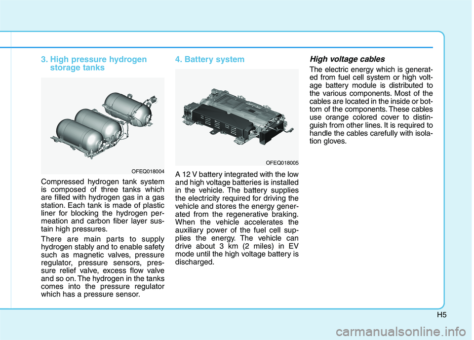
3. High pressure hydrogenstorage tanks
Compressed hydrogen tank system is composed of three tanks which
are filled with hydrogen gas in a gas
station. Each tank is made of plastic
liner for blocking the hydrogen per-
meation and carbon fiber layer sus-
tain high pressures.
There are main parts to supply
hydrogen stably and to enable safety
such as magnetic valves, pressure
regulator, pressure sensors, pres-
sure relief valve, excess flow valve
and so on. The hydrogen in the tankscomes into the pressure regulator
which has a pressure sensor.
4. Battery system
A 12 V battery integrated with the low
and high voltage batteries is installed
in the vehicle. The battery supplies
the electricity required for driving the
vehicle and stores the energy gener-
ated from the regenerative braking.
When the vehicle accelerates the
auxiliary power of the fuel cell sup-
plies the energy. The vehicle can
drive about 3 km (2 miles) in EV
mode until the high voltage battery isdischarged.
High voltage cables
The electric energy which is generat-
ed from fuel cell system or high volt-
age battery module is distributed to
the various components. Most of the
cables are located in the inside or bot-
tom of the components. These cables
use orange colored cover to distin-
guish from other lines. It is required to
handle the cables carefully with isola-
tion gloves.
OFEQ018004
OFEQ018005
Page 508 of 558
H6
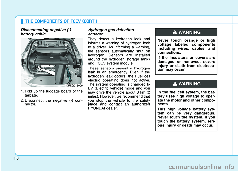
Disconnecting negative (-) battery cable
1. Fold up the luggage board of the tailgate.
2. Disconnect the negative (-) con- nector.
Hydrogen gas detection
sensors
They detect a hydrogen leak and
informs a warning of hydrogen leak
to a driver. As informing a warning,the sensors automatically shut off
hydrogen. Sensors are installed
around the hydrogen storage tanks
and FCEV system module.
These sensors prevent a hydrogen
leak in an emergency. Even if the
hydrogen leak occurs, the Fuel cell
electric operating does not active.
The system operating is changed to
EV (Electric vehicle) mode and you
may drive the vehicle about 3 km (2
miles). However, we recommend that
you stop the vehicle to the safety
place and contact an authorized
HYUNDAI dealer.
OFEQ018009
TT HH EE CC OO MM PPOO NNEENN TTSS OO FF FF CC EE VV (( CC OO NNTT..))
Never touch orange or high
voltage labeled components
including wires, cables, andconnections.
If the insulators or covers are
damaged or removed, severe
injury or death from electrocu-
tion may occur.
WARNING
In the fuel cell system, the bat-
tery uses high voltage to oper-ate the motor and other compo-nents.
This high voltage battery sys-
tem can be very dangerous.
Never touch the system. If you
touch the battery system, seri-
ous injury or death may occur.
WARNING
Page 517 of 558
H15
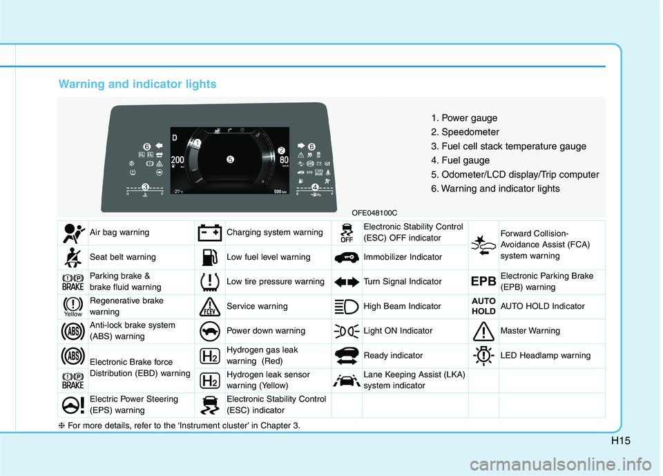
Warning and indicator lights
OFE048100C1. Power gauge
2. Speedometer
3. Fuel cell stack temperature gauge
4. Fuel gauge
5. Odometer/LCD display/Trip computer
6. Warning and indicator lights
Air bag warningCharging system warningElectronic Stability Control (ESC) OFF indicator Forward Collision-
Avoidance Assist (FCA)
system warning
Seat belt warningLow fuel level warning Immobilizer Indicator
Parking brake &
brake fluid warningLow tire pressure warningTurn Signal IndicatorEPBElectronic Parking Brake
(EPB) warning
Regenerative brake
warningService warning High Beam IndicatorAUTO
HOLDAUTO HOLD Indicator
Anti-lock brake system
(ABS) warningPower down warning Light ON IndicatorMaster Warning
Electronic Brake force
Distribution (EBD) warning
Hydrogen gas leak
warning (Red) Ready indicatorLED Headlamp warning
Hydrogen leak sensor
warning (Yellow)Lane Keeping Assist (LKA) system indicator
Electric Power Steering
(EPS) warningElectronic Stability Control (ESC) indicator
Yellow
❈ For more details, refer to the ‘Instrument cluster’ in Chapter 3.
Page 520 of 558
H18
FFEE AA TTUU RREESS OO FF FF CC EE VV (( CC OO NNTT..))
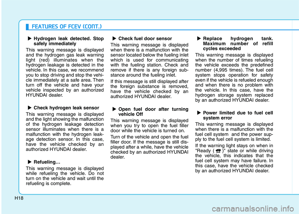
Hydrogen leak detected. Stop
safely immediately
This warning message is displayed
and the hydrogen gas leak warninglight (red) illuminates when the
hydrogen leakage is detected in the
vehicle. In this case, we recommend
you to stop driving and stop the vehi-
cle immediately at a safe area. Then
turn off the vehicle and have your
vehicle inspected by an authorized
HYUNDAI dealer.
Check hydrogen leak sensor
This warning message is displayed
and the light showing the malfunction
of the hydrogen leakage detectionsensor illuminates when there is a
malfunction with the hydrogen leak-
age detection sensor. In this case,
have the vehicle checked by an
authorized HYUNDAI dealer.
Refueling…
This warning message is displayed
while refueling the vehicle. Do not
turn on the vehicle and wait until the
refueling is complete. Check fuel door sensor
This warning message is displayedwhen there is a malfunction with the
sensor located below the fueling inlet
which is used for communicating
with the fueling station. Check and
remove if there is any foreign sub-stance around the fueling inlet.
If this message is still displayed after
the foreign substance is removed,
have the vehicle checked by an
authorized HYUNDAI dealer.
Open fuel door after turning
vehicle Off
This warning message is displayed
when you try to open the fuel filler
door while the vehicle is turned on.
Turn of the vehicle and open the fuel
filler door. If the message is still dis-
played after a while, have the vehicle
checked by an authorized HYUNDAI
dealer. Replace hydrogen tank.
Maximum number of refill
cycles exceeded
This warning message is displayed
when the number of times refueling
the vehicle exceeds the predefined
number (4,995 times). The fuel cell
system stops operation for safety
even if the vehicle is refueled enough
and when there is no problem with
the vehicle. In this case, have the
hydrogen storage system replaced
by an authorized HYUNDAI dealer.
Power limited due to fuel cell
system error
This warning message is displayedwhen there is a malfunction with the
fuel cell system and the power sup-ply to the fuel cell system is limited.
If the warning light stays on when in
"Ready ( )" state or while driving
the vehicle, this indicates that the
fuel cell system may have failure. In
this case, have the vehicle checked
by an authorized HYUNDAI dealer.
▲▲
▲
▲
▲
▲
▲
▲
▲
▲
▲
▲
▲
▲
Page 544 of 558
H42
CategoryQuestionsAnswers
Fuel Cell
Stack/High VoltageBattery
(4 items)
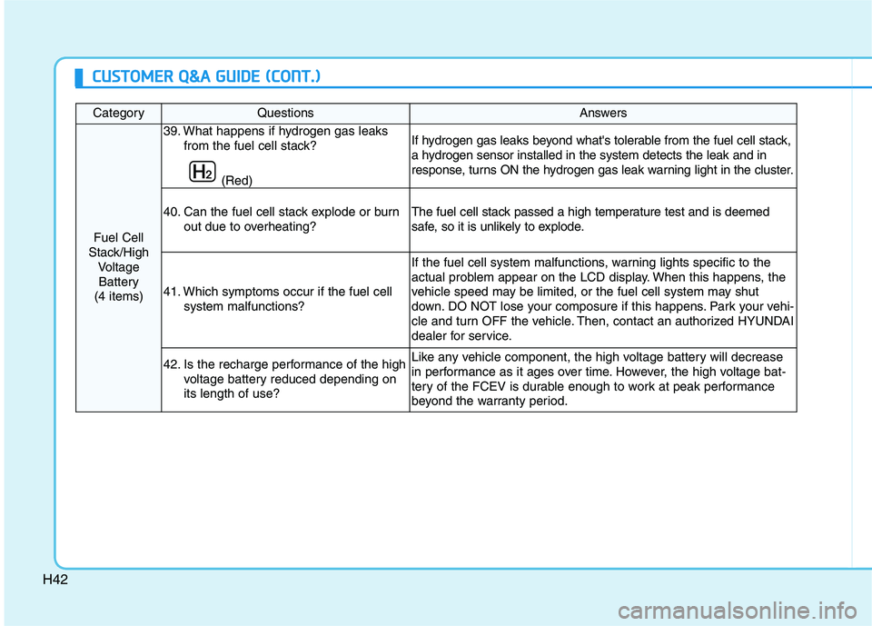
39. What happens if hydrogen gas leaks
from the fuel cell stack?
(Red)If hydrogen gas leaks beyond what's tolerable from the fuel cell stack,
a hydrogen sensor installed in the system detects the leak and in
response, turns ON the hydrogen gas leak warning light in the cluster.
40. Can the fuel cell stack explode or burnout due to overheating?The fuel cell stack passed a high temperature test and is deemed
safe, so it is unlikely to explode.
41. Which symptoms occur if the fuel cellsystem malfunctions?
If the fuel cell system malfunctions, warning lights specific to the
actual problem appear on the LCD display. When this happens, the
vehicle speed may be limited, or the fuel cell system may shut
down. DO NOT lose your composure if this happens. Park your vehi-
cle and turn OFF the vehicle. Then, contact an authorized HYUNDAI
dealer for service.
42. Is the recharge performance of the high
voltage battery reduced depending on its length of use? Like any vehicle component, the high voltage battery will decrease
in performance as it ages over time. However, the high voltage bat-
tery of the FCEV is durable enough to work at peak performance
beyond the warranty period.
CCUU SSTT OO MM EERR QQ &&AA GG UU IIDD EE (( CC OO NNTT..))
Page 545 of 558
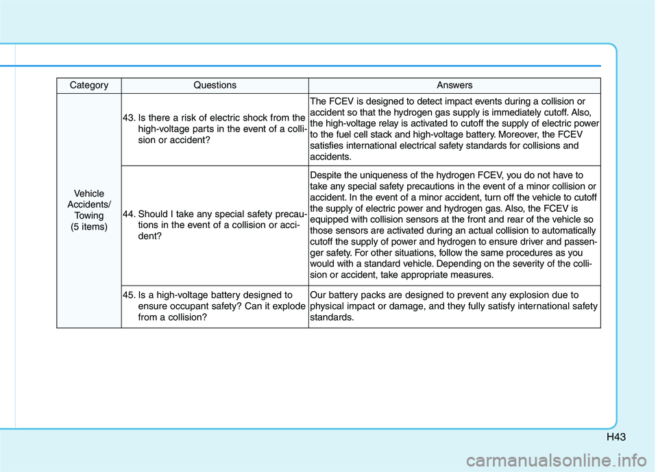
H43
CategoryQuestionsAnswers
Vehicle
Accidents/ Towing
(5 items)
43. Is there a risk of electric shock from the high-voltage parts in the event of a colli- sion or accident?
The FCEV is designed to detect impact events during a collision or
accident so that the hydrogen gas supply is immediately cutoff. Also,
the high-voltage relay is activated to cutoff the supply of electric power
to the fuel cell stack and high-voltage battery. Moreover, the FCEV
satisfies international electrical safety standards for collisions and
accidents.
44. Should I take any special safety precau-tions in the event of a collision or acci- dent?
Despite the uniqueness of the hydrogen FCEV, you do not have to
take any special safety precautions in the event of a minor collision or
accident. In the event of a minor accident, turn off the vehicle to cutoff
the supply of electric power and hydrogen gas. Also, the FCEV is
equipped with collision sensors at the front and rear of the vehicle so
those sensors are activated during an actual collision to automatically
cutoff the supply of power and hydrogen to ensure driver and passen-
ger safety. For other situations, follow the same procedures as you
would with a standard vehicle. Depending on the severity of the colli-
sion or accident, take appropriate measures.
45. Is a high-voltage battery designed toensure occupant safety? Can it explode from a collision?Our battery packs are designed to prevent any explosion due to
physical impact or damage, and they fully satisfy international safety
standards.
Page 549 of 558
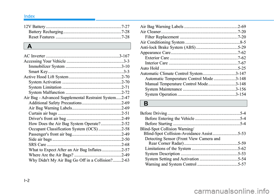
I-2
12V Battery .....................................................................7-27
Battery Recharging .....................................................7-28
Reset Features ............................................................7-28
AC Inverter ...................................................................3-167
Accessing Your Vehicle ....................................................3-3 Immobilizer System ...................................................3-10
Smart Key.....................................................................3-3
Active Hood Lift System ................................................2-70 System Activation ......................................................2-70
System Limitation ......................................................2-71
System Malfunction ...................................................2-72
Air Bag - Advanced Supplemental Restraint System.....2-47 Additional Safety Precautions ....................................2-69
Air Bag Warning Labels.............................................2-69
Curtain air bags ..........................................................2-51
Driver's front air bag ..................................................2-49
How Does the Air Bag System Operate? ...................2-52
Occupant Classification System (OCS) .....................2-58
Passenger's front air bag.............................................2-49
Side air bags ...............................................................2-50
SRS Care ....................................................................2-68
What to Expect After an Air Bag Inflates ..................2-57
Where Are the Air Bags? ...........................................2-49
Why Didn't My Air Bag Go Off in a Collision?........2-63 Air Bag Warning Labels .................................................2-69
Air Cleaner......................................................................7-20
Filter Replacement .....................................................7-20
Air Conditioning System ..................................................8-5
Anti-lock Brake System (ABS) ......................................5-29
Appearance Care .............................................................7-62 Exterior Care ..............................................................7-62
Interior Care ...............................................................7-67
Auto Hold .......................................................................5-25
Automatic Climate Control System..............................3-147 Automatic Temperature Control Mode ....................3-148
Manual Temperature Control Mode .........................3-148
System Maintenance ................................................3-156
System Operation .....................................................3-154
Before Driving ..................................................................5-4 Before Entering the Vehicle .........................................5-4
Before Starting .............................................................5-4
Blind-Spot Collision Warning/ Blind-Spot Collision-Avoidance Assist .......................5-53
Detecting Sensor (Front View Camera and Rear Corner Radar) .................................................5-59
Limitations of the System ..........................................5-62
System Description ....................................................5-53
System Setting and Activation ...................................5-54
Warning and System Control .....................................5-57
Index
A
B