power steering Hyundai Santa Fe 2009 Owner's Manual - RHD (UK, Australia)
[x] Cancel search | Manufacturer: HYUNDAI, Model Year: 2009, Model line: Santa Fe, Model: Hyundai Santa Fe 2009Pages: 269, PDF Size: 9.78 MB
Page 9 of 269
F9
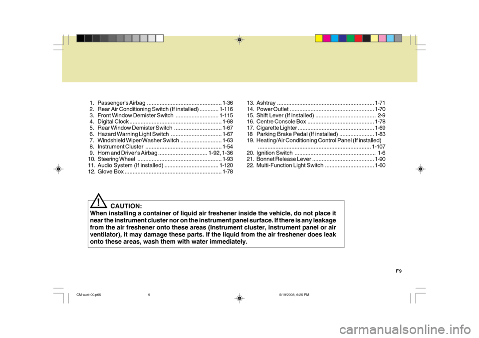
1. Passenger's
Airbag............................................... 1-36
2. Rear Air Conditioning Sw itch (If installed) ............1-116
3. Front Window Demister Switch........................... 1-115
4. Digital Clock .......................................................... 1-68
5. Rear Window Demi ster Switch .............................. 1-67
6. Hazard Warning Light Switch................................ 1-67
7. Windshield W iper/Washer Switch ..........................1-63
8. Instrument Cluster ................................................ 1-54
9. Horn and Driver' s Airbag ............................... 1-92, 1-36
10. Steering Wheel ..................................................... 1-93
11. Audio System (If installed) .................................. 1-120
12. Glove Box ............................................................. 1-78
CAUTION:
When installing a container of liquid air freshener inside the vehicle, do not place it near the instrument cluster nor on the instrument panel surface. If there is any leakagefrom the air freshener onto these areas (Instrument cluster, instrument panel or airventilator), it may damage these parts. If the liquid from the air freshener does leakonto these areas, wash them with water immediately.
! 13. Ashtray
............................................................. 1-71
14. Power Outlet ..................................................... 1-70
15. Shift Lever (If installed) ...................................... 2-9
16. Centre Console Box .......................................... 1-78
17. Cigarette Lighter ................................................ 1-69
18 Parking Brake Pedal (If installed) ...................... 1-83
19. Heating/Air Conditioning Control Panel (If installed)
....................................................................... 1-107
20. Ignition Switch ................................................... 1-6
21. Bonnet Release Lever ....................................... 1-90
22. Multi-Function Light Switch ............................... 1-60
CM-aust-00.p65 5/19/2008, 6:25 PM
9
Page 29 of 269
1FEATURES OF YOUR HYUNDAI
18
!
!
B090A01TG-DAT FRONT POWER SEATS (If Installed) The front seats can be adjusted appro- priately by using the control knob of theseat. Before driving away, adjust the seat to the proper position so as to easily control the steering wheel, ped-als and switches on the instrument panel.
CAUTION:
Do not operate two knobs at the same time.
WARNING:
o Never attempt to adjust the seat while the vehicle is moving. This could result in loss of control, and an accident causing death, seri-ous injury, or property damage.
o Sitting or leaning unnecessarily
close to the front airbags mayresult in reduced protection in case of airbag deployment during a vehicle accident.
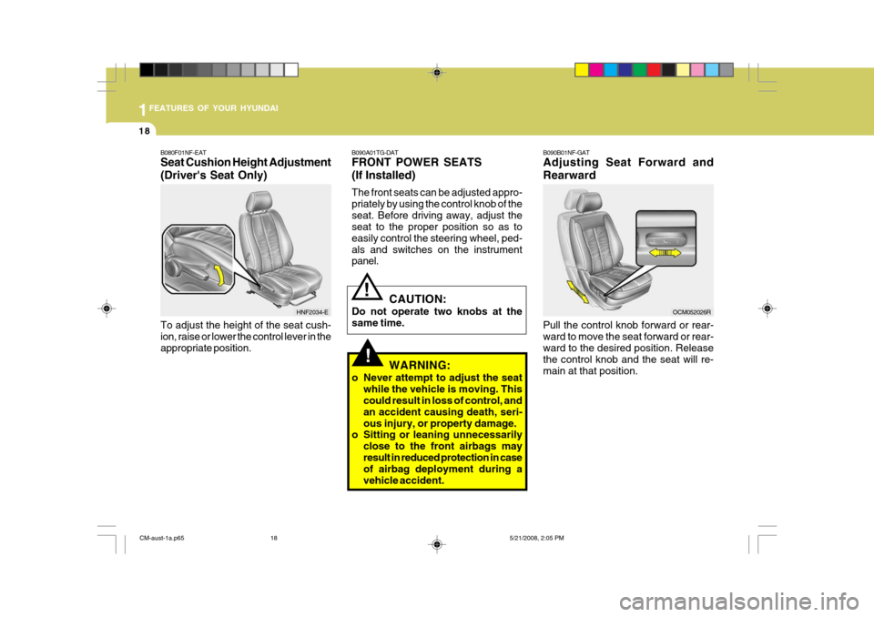
B080F01NF-EAT Seat Cushion Height Adjustment (Driver's Seat Only) To adjust the height of the seat cush- ion, raise or lower the control lever in theappropriate position.
HNF2034-E
B090B01NF-GAT Adjusting Seat Forward and Rearward Pull the control knob forward or rear- ward to move the seat forward or rear-ward to the desired position. Release the control knob and the seat will re- main at that position.OCM052026R
CM-aust-1a.p65
5/21/2008, 2:05 PM
18
Page 164 of 269
2
DRIVING YOUR HYUNDAI
19
!
4WD LOCK SYSTEM
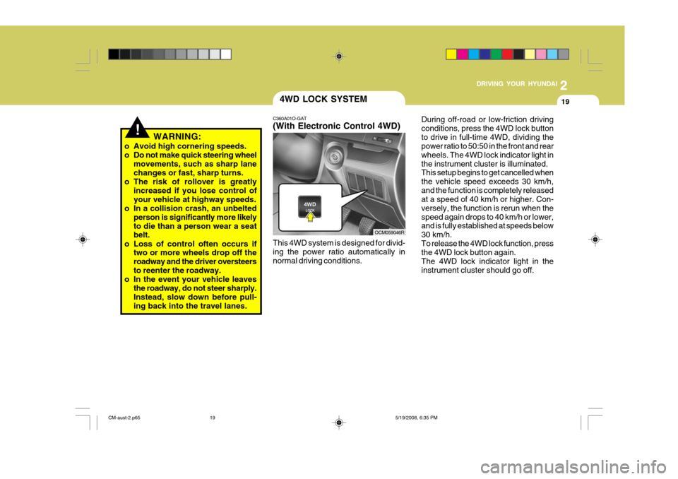
C360A01O-GAT (With Electronic Control 4WD) This 4WD system is designed for divid- ing the power ratio automatically innormal driving conditions. During off-road or low-friction drivingconditions, press the 4WD lock buttonto drive in full-time 4WD, dividing the power ratio to 50:50 in the front and rear wheels. The 4WD lock indicator light inthe instrument cluster is illuminated. This setup begins to get cancelled when the vehicle speed exceeds 30 km/h,and the function is completely released at a speed of 40 km/h or higher. Con- versely, the function is rerun when thespeed again drops to 40 km/h or lower, and is fully established at speeds below 30 km/h.To release the 4WD lock function, press the 4WD lock button again. The 4WD lock indicator light in theinstrument cluster should go off.
OCM059046R
WARNING:
o Avoid high cornering speeds.
o Do not make quick steering wheel movements, such as sharp lane changes or fast, sharp turns.
o The risk of rollover is greatly increased if you lose control ofyour vehicle at highway speeds.
o In a collision crash, an unbelted person is significantly more likelyto die than a person wear a seat belt.
o Loss of control often occurs if two or more wheels drop off the roadway and the driver oversteersto reenter the roadway.
o In the event your vehicle leaves the roadway, do not steer sharply. Instead, slow down before pull- ing back into the travel lanes.
CM-aust-2.p65 5/19/2008, 6:35 PM
19
Page 188 of 269
3
WHAT TO DO IN AN EMERGENCY
13
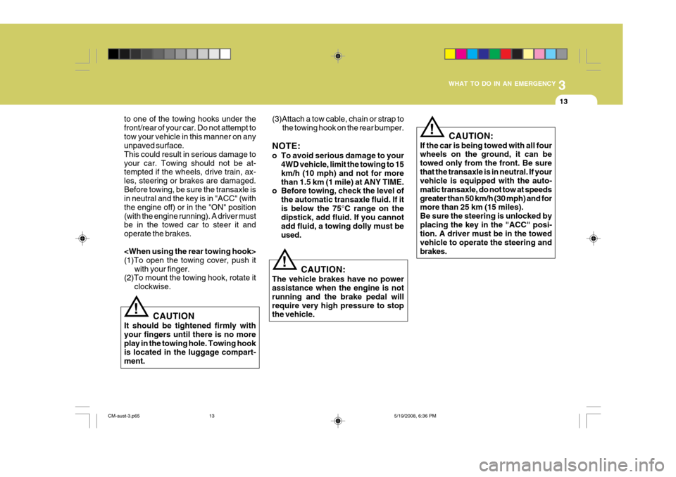
to one of the towing hooks under the front/rear of your car. Do not attempt totow your vehicle in this manner on any unpaved surface. This could result in serious damage toyour car. Towing should not be at- tempted if the wheels, drive train, ax- les, steering or brakes are damaged.Before towing, be sure the transaxle is in neutral and the key is in "ACC" (with the engine off) or in the "ON" position(with the engine running). A driver must be in the towed car to steer it and operate the brakes.
(2)To mount the towing hook, rotate it
clockwise. (3)Attach a tow cable, chain or strap to
the towing hook on the rear bumper.
NOTE:
o To avoid serious damage to your 4WD vehicle, limit the towing to 15 km/h (10 mph) and not for morethan 1.5 km (1 mile) at ANY TIME.
o Before towing, check the level of
the automatic transaxle fluid. If itis below the 75°C range on the dipstick, add fluid. If you cannot add fluid, a towing dolly must beused.
!
! CAUTION
It should be tightened firmly with your fingers until there is no more play in the towing hole. Towing hook is located in the luggage compart-ment. CAUTION:
If the car is being towed with all four wheels on the ground, it can be towed only from the front. Be surethat the transaxle is in neutral. If your vehicle is equipped with the auto- matic transaxle, do not tow at speedsgreater than 50 km/h (30 mph) and for more than 25 km (15 miles). Be sure the steering is unlocked byplacing the key in the "ACC" posi- tion. A driver must be in the towed vehicle to operate the steering andbrakes.
! CAUTION:
The vehicle brakes have no power assistance when the engine is not running and the brake pedal willrequire very high pressure to stop the vehicle.
CM-aust-3.p65 5/19/2008, 6:36 PM
13
Page 202 of 269
5VEHICLE MAINTENANCE REQUIREMENTS
6
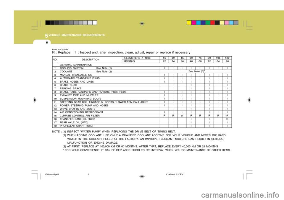
F030C02CM-DAT R : Replace I : Inspect and, after inspection, clean, adjust, repair or replace if necessary
NOTE : (1) INSPECT "WATER PUMP" WHEN REPLACING THE DRIVE BELT OR TIMING BELT. (2) WHEN ADDING COOLANT, USE ONLY A QUALIFIED COOLANT ADDITIVE FOR YOUR VEHICLE AND NEVER MIX HARD
WATER IN THE COOLANT FILLED AT THE FACTORY. AN IMPROPER COOLANT MIXTURE CAN RESULT IN SERIOUS MALFUNCTION OR ENGINE DAMAGE.
(3) AT FIRST, REPLACE AT 100,000 KM OR 60 MONTHS: AFTER THAT, REPLACE EVERY 40,000 KM OR 24 MONTHS * FOR YOUR CONVENIENCE, IT CAN BE REPLACED PRIOR TO IT'S INTERVAL WHEN YOU DO MAINTENANCE OF OTHER ITEMS. 75 60
I I II I I III I
R 90 72
I I IIIII I IIIII
R
III
1512
I I II I I III I
R See Note (3)*
DESCRIPTION
GENERAL MAINTENANCE
COOLING SYSTEM See Note (1)COOLANT See Note (2)
MANUAL TRANSAXLE OIL AUTOMATIC TRANSAXLE FLUID BRAKE HOSES AND LINESBRAKE FLUIDPARKING BRAKEBRAKE PADS, CALIPERS AND ROTORS (Front, Rear)EXHAUST PIPE AND MUFFLER SUSPENSION MOUNTING BOLTS STEERING GEAR BOX, LINKAGE & BOOTS / LOWER ARM BALL JOINTPOWER STEERING PUMP AND HOSESDRIVE SHAFTS AND BOOTSAIR CONDITIONING REFRIGERANTCLIMATE CONTROL AIR FILTERTRANSFER CASE OIL (4WD) REAR AXLE OIL (4WD) PROPELLAR SHAFT (4WD)
NO.
123 4 56789
10111213141516 17 18
30 24
I I IIIII I IIIII
R
III 4536
I I II I IIII I
R 60 48
I I IIIII I IIIII
R
III 105
84
I I II I I III I
R 120
96
I I IIIII I IIIII
R R I IKILOMETERS X 1000 MONTHS
CM-aust-5.p65 5/19/2008, 6:37 PM
6
Page 207 of 269
5
VEHICLE MAINTENANCE REQUIREMENTS
11
F070M01A-AAT
o Steering Gear Box, Linkage &
Boots/Lower Arm Ball Joint
With the vehicle stopped and engine off, check for excessive free-play in the steering wheel. Check the linkage for bends or damage. Check the dustboots and ball joints for deterioration, cracks, or damage. Replace any dam- aged parts. F070N01A-AAT
o Power Steering Pump,
Belt and Hoses
Check the power steering pump and hoses for leakage and damage. Re-place any damaged or leaking parts immediately. Inspect the power steer- ing belt for evidence of cuts, cracks,excessive wear, oiliness and proper tension. Replace or adjust it if neces- sary. F070P01A-AAT
o Drive Shafts and Boots
Check the drive shafts, boots and
clamps for cracks, deterioration, or damage. Replace any damaged parts and, if necessary, repack the grease.
F070Q01A-AAT
o Air Conditioning Refrigerant
Check the air conditioning lines and
connections for leakage and damage.Check air conditioning performance according to the relevant shop manual if necessary.
CM-aust-5.p65 5/19/2008, 6:37 PM
11
Page 208 of 269
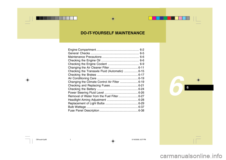
Engine Compartment .................................................... 6-2
General Checks ........................................................... 6-5
Maintenance Precautions ............................................. 6-6
Checking the Engine Oil .............................................. 6-6
Checking the Engine Coolant ...................................... 6-9
Changing the Air Cleaner Filter ...................................6-11
Checking the Transaxle Fluid (Automatic) .................6-15
Checking the Brakes .................................................. 6-17
Air Conditioning Care .................................................. 6-19
Changing the Climate Control Air Filter .. ....................6-19
Checking and Replacing Fuses ..................................6-21
Checking the Battery .................................................. 6-24
Power Steering Fluid Level ......................................... 6-26
Removal of Water from the Fuel Filter ........................6-27
Headlight Aiming Adjustment ...................................... 6-28
Replacement of Light Bulbs ........................................6-29
Bulb Wattage ............................................................... 6-37
Fuse Panel D escription ............................................... 6-38
DO-IT-YOURSELF MAINTENANCE
6
6
CM-aust-6.p65
5/19/2008, 6:37 PM
1
Page 209 of 269
6DO-IT-YOURSELF MAINTENANCE
2ENGINE COMPARTMENT
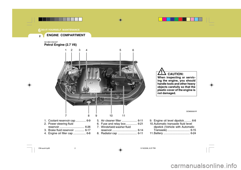
1. Coolant rese rvoir cap ............. 6-9
2. Power steering fluid
reservoir ............................... 6-26
3. Brake fluid reservoir ............ 6-17
4. Engine oil filler cap ................ 6-8 5. Air cleaner filter ...................
6-11
6. Fuse and relay box .............. 6-21
7. Windshield washer fluid reservoir ............................... 6-14
8. Radiator cap ........................6-11
G010B01CM-DAT Petrol Engine (2.7 V6)
9. Engine oil level dipstick ......... 6-8
10. Automatic transaxle fluid leveldipstick (Vehicle with AutomaticTransaxle) ............................ 6-15
11. Battery ................................. 6-24
CAUTION:
When inspecting or servic-
ing the engine, you shouldhandle tools and other heavyobjects carefully so that the plastic cover of the engine is not damaged.
!
OCM055001R
CM-aust-6.p65 5/19/2008, 6:37 PM
2
Page 210 of 269
6
DO-IT-YOURSELF MAINTENANCE
3
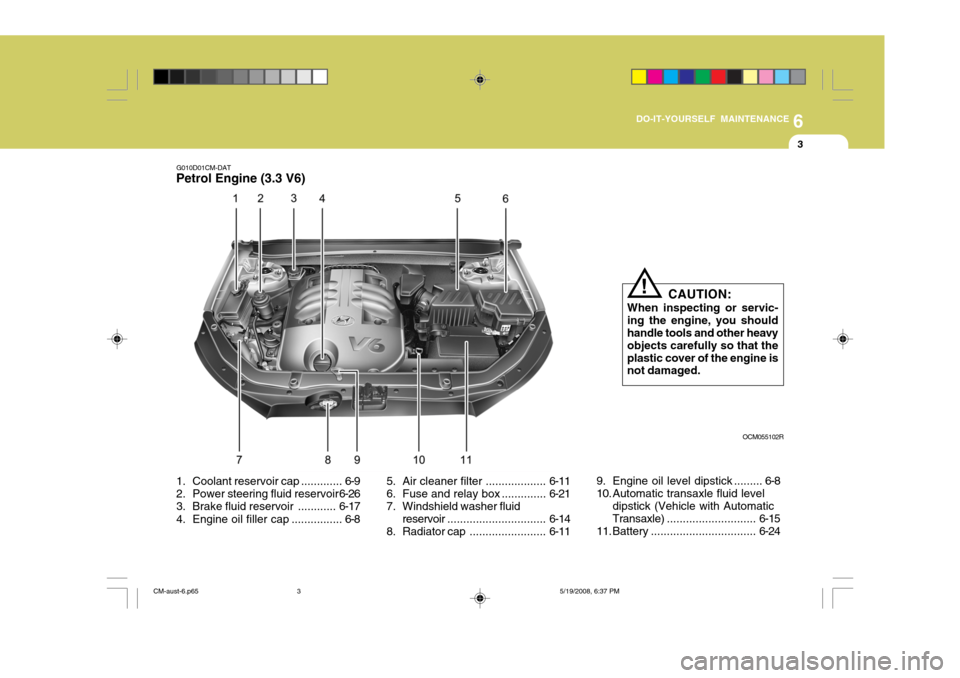
G010D01CM-DAT
Petrol Engine (3.3 V6)
CAUTION:
When inspecting or servic- ing the engine, you shouldhandle tools and other heavy objects carefully so that the plastic cover of the engine is not damaged.
!
OCM055102R
1. Coolant rese rvoir cap ............. 6-9
2. Power steering fluid reservoir 6-26
3. Brake fluid reservoir ............ 6-17
4. Engine oil filler cap ................ 6-8 5. Air cleaner filter ...................
6-11
6. Fuse and relay box .............. 6-21
7. Windshield washer fluid
reservoir ............................... 6-14
8. Radiat or cap........................ 6-119. Engine oil level dipstick ......... 6-8
10. Automatic transaxle fluid level
dipstick (Vehicle with AutomaticTransaxle) ............................ 6-15
11. Battery ................................. 6-24
CM-aust-6.p65 5/19/2008, 6:37 PM
3
Page 211 of 269
6DO-IT-YOURSELF MAINTENANCE
4
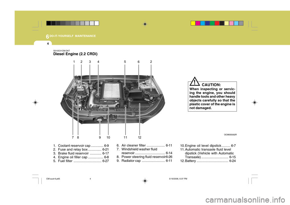
1. Coolant rese rvoir cap ............. 6-9
2. Fuse and relay box .............. 6-21
3. Brake fluid reservoir ............ 6-17
4. Engine oil filler cap ................ 6-8
5. Fuel filter ............................. 6-276. Air cleaner filter ...................
6-11
7. Windshield washer fluid
reservoir ............................... 6-14
8. Power steering fluid reservoir 6-26
9. Radiator cap ........................6-1110. Engine oil level dipstick ......... 6-7
11. Automatic transaxle fluid level
dipstick (Vehicle with AutomaticTransaxle) ............................ 6-15
12. Battery ................................. 6-24
G010C01CM-DAT
Diesel Engine (2.2 CRDi)
CAUTION:
When inspecting or servic-
ing the engine, you should handle tools and other heavy objects carefully so that theplastic cover of the engine is not damaged.
!
OCM055002R
CM-aust-6.p65 5/19/2008, 6:37 PM
4