Hyundai Terracan 2004 Owner's Manual
Manufacturer: HYUNDAI, Model Year: 2004, Model line: Terracan, Model: Hyundai Terracan 2004Pages: 361, PDF Size: 4.69 MB
Page 261 of 361
CONTROLS AND EQUIPMENT1- 61
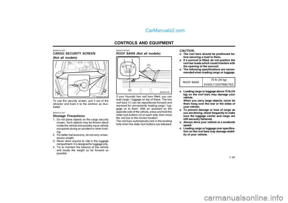
B640A01S-EAT CARGO SECURITY SCREEN (Not all models) To use the security screen, pull it out of the retractor and hook it to the anchors as illus-trated. B650A01S-AAT Stowage Precautions
1. Do not place objects on the cargo security screen. Such objects may be thrown about inside the vehicle and possibly injure vehicleoccupants during an accident or when brak-ing.
2. For better fuel economy, do not carry unnec- essary weight.
3. Never allow anyone to ride in the luggage compartment. It is designed for luggage only.
4. Try to maintain the balance of the vehicle and locate the weight as far forward aspossible.
B640A01HP-E
75 lb (34 kg)
EVENLY DISTRIBUTED
B630A01HP
B630A01HP-EAT ROOF BARS (Not all models) If your Hyundai has roof bars fitted, you can
load cargo / luggage on top of these. The two roof bars (1) can be repositioned forward andrearward for conveniently loading cargo / lug-gage on to them. With an assistant on theopposite side of the vehicle, press and hold theslider lock buttons (2) on each side, then movethe roof bar to the correct location.
The roof bars automatically lock in the locating
hole when the slider lock buttons are released.
ROOF BARS
(2) o Loading cargo or luggage above 75 lb (34
kg) on the roof bars may damage your vehicle. When you carry large objects, never let them hang over the rear or the sides ofyour vehicle.
o To prevent damage or loss of cargo as you are driving, check frequently to makesure the luggage carrier and cargo arestill securely fastened.
o Always drive your vehicle at a moderate speed.
o Loading cargo or luggage over specifica- tion on the roof bars may damage stabil-ity of your vehicle.
(1)
CAUTION:
o The roof bars should be positioned be- fore securing a load to them.
o If a sunroof is fitted, do not position the roof bar loads which could interfere with the opening of the sunroof.
o The following specifications are recom- mended when loading cargo or luggage.
Page 262 of 361
CONTROLS AND EQUIPMENT
1- 62
WARNING: Fuel vapors are dangerous. Before refuel-
ing, always stop the engine and never allowsparks or open flames near the filler area. Ifyou need to replace the filler cap, use agenuine Hyundai replacement part.
If you open the fuel filler cap during high
ambient temperatures, a slight "pressuresound" may be heard. This is normal andnot a cause for concern.
Whenever you open the fuel filler cap, turn
it slowly.
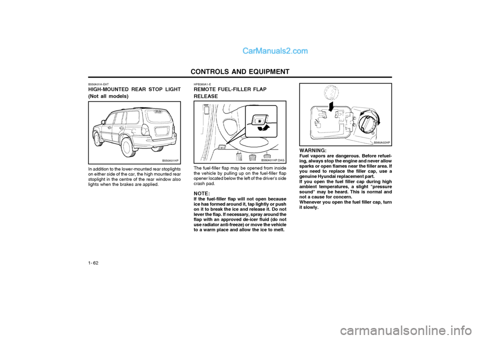
The fuel-filler flap may be opened from insidethe vehicle by pulling up on the fuel-filler flapopener located below the left of the driver's sidecrash pad. NOTE: If the fuel-filler flap will not open because ice has formed around it, tap lightly or pushon it to break the ice and release it. Do notlever the flap. If necessary, spray around theflap with an approved de-icer fluid (do notuse radiator anti-freeze) or move the vehicleto a warm place and allow the ice to melt.
HPB360A1-E REMOTE FUEL-FILLER FLAP RELEASE
B560A01HP.DAG
In addition to the lower-mounted rear stoplights on either side of the car, the high mounted rearstoplight in the centre of the rear window alsolights when the brakes are applied.
B550A01A-EAT HIGH-MOUNTED REAR STOP LIGHT (Not all models)B550A01HP
B560A02HP
Page 263 of 361
CONTROLS AND EQUIPMENT1- 63
B570A02HP
DB370A2-E BONNET RELEASE
B570A01HP.DAG
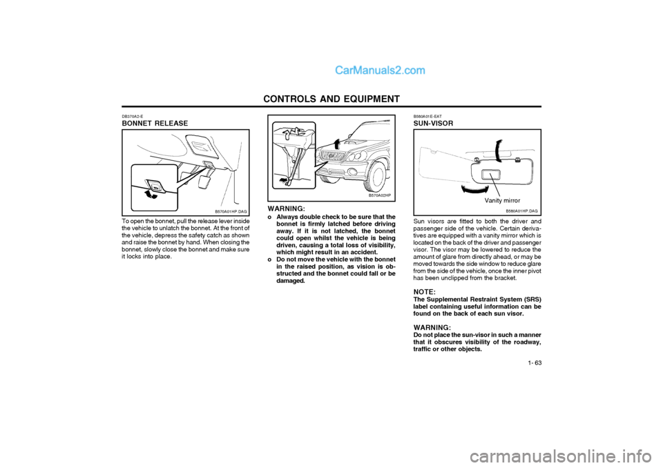
To open the bonnet, pull the release lever inside
the vehicle to unlatch the bonnet. At the front of the vehicle, depress the safety catch as shownand raise the bonnet by hand. When closing thebonnet, slowly close the bonnet and make sureit locks into place. WARNING:
o Always double check to be sure that the bonnet is firmly latched before drivingaway. If it is not latched, the bonnetcould open whilst the vehicle is beingdriven, causing a total loss of visibility,which might result in an accident.
o Do not move the vehicle with the bonnet in the raised position, as vision is ob-structed and the bonnet could fall or bedamaged. B580A01E-EAT SUN-VISORB580A01HP.DAG
Vanity mirror
Sun visors are fitted to both the driver and
passenger side of the vehicle. Certain deriva- tives are equipped with a vanity mirror which islocated on the back of the driver and passengervisor. The visor may be lowered to reduce theamount of glare from directly ahead, or may bemoved towards the side window to reduce glarefrom the side of the vehicle, once the inner pivothas been unclipped from the bracket.
NOTE: The Supplemental Restraint System (SRS)
label containing useful information can be found on the back of each sun visor.
WARNING:Do not place the sun-visor in such a manner
that it obscures visibility of the roadway,traffic or other objects.
Page 264 of 361
CONTROLS AND EQUIPMENT
1- 64 HPB830A1-E PACKAGE ARM REST (Not all models)
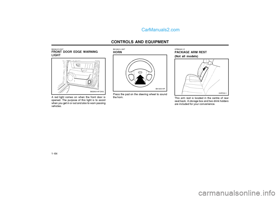
Press the pad on the steering wheel to sound the horn.
B610A01L-GAT HORN
This arm rest is located in the centre of rear seat back. A storage box and two drink holdersare included for your convenience.HHP232-1
A red light comes on when the front door isopened. The purpose of this light is to assistwhen you get in or out and also to warn passingvehicles.
B620A01S-EAT FRONT DOOR EDGE WARNING LIGHTB620A01HP.DAGB610A01HP
Page 265 of 361
CONTROLS AND EQUIPMENT1- 65
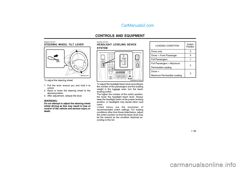
To adjust the steering wheel:
1. Pull the lever toward you and hold it to unlock.
2. Raise or lower the steering wheel to the desired position.
3. After adjustment, release the lever.
WARNING: Do not attempt to adjust the steering wheel
whilst driving as this may result in loss ofcontrol of the vehicle and serious injury ordeath. B600A01HP-EAT STEERING WHEEL TILT LEVER
B600A01HP
Driver only Driver + Front Passenger Full Passengers Full Passengers + Maximum Permissible Loading Driver + Maximum Permissible Loading0 0 1 2 3
LOADING CONDITION
Switch
Position
To adjust the headlight beam level according to
the number of the passengers and the loading weight in the luggage area, turn the beamleveling switch.
The higher the number of the switch position,
the lower the headlight beam level. Alwayskeep the headlight beam at the proper levelingposition, or headlights may dazzle other roadusers.
Listed below are the examples of
recommeneded switch settings. For loadingconditions other than those listed below, adjustthe switch position so that the beam level maybe the nearest as the condition obtained ac-cording to the list. B340G01HP-EAT HEADLIGHT LEVELING DEVICE SYSTEM
B340G01HP.DAG
Page 266 of 361
CONTROLS AND EQUIPMENT
1- 66 B660A01S-EAT CRUISE CONTROL (Not all models)
B660C02L-AATTo Cancel the Cruise Speed
B660B02L-EATTo Set the Cruise Speed
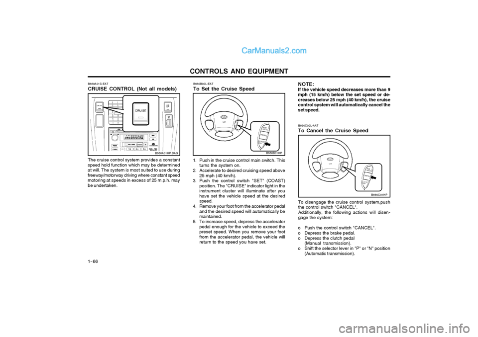
The cruise control system provides a constant
speed hold function which may be determined at will. The system is most suited to use duringfreeway/motorway driving where constant speedmotoring at speeds in excess of 25 m.p.h. maybe undertaken.
B660A01HP.DAG
1. Push in the cruise control main switch. This turns the system on.
2. Accelerate to desired cruising speed above 25 mph (40 km/h).
3. Push the control switch "SET" (COAST) position. The "CRUISE" indicator light in the instrument cluster will illuminate after youhave set the vehicle speed at the desiredspeed.
4. Remove your foot from the accelerator pedal and the desired speed will automatically bemaintained.
5. To increase speed, depress the accelerator pedal enough for the vehicle to exceed thepreset speed. When you remove your footfrom the accelerator pedal, the vehicle willreturn to the speed you have set.
B660B01HP
NOTE: If the vehicle speed decreases more than 9mph (15 km/h) below the set speed or de-creases below 25 mph (40 km/h), the cruisecontrol system will automatically cancel theset speed.
To disengage the cruise control system,pushthe control switch "CANCEL". Additionally, the following actions will disen- gage the system:
o Push the control switch "CANCEL".
o Depress the brake pedal.
o Depress the clutch pedal (Manual transmission).
o Shift the selector lever in "P" or "N" position (Automatic transmission).
B660C01HP
Page 267 of 361
CONTROLS AND EQUIPMENT1- 67
WARNING:
o Keep the main switch off when not using
the cruise control.Use the cruise control system only when traveling on open highways in goodweather.
o Do not use the cruise control when it may not be safe to keep the car at aconstant speed, for instance, driving inheavy or varying traffic, or on slippery(rainy, icy or snow-covered) or windingroads or over 6% up-hill or down-hillroads.
o Pay particular attention to the driving conditions whenever using the cruisecontrol system.
o During cruise-speed driving with manual transmission vehicle, do not shift intoneutral without depressing the clutchpedal, since the engine will be overrevved.If this happens, depress the clutch pedalor release the main switch.
o During normal cruise control operation, when the set button is activated or reac-tivated after applying the brakes, thecruise control will energize after approxi-mately 3 seconds. This delay is normal.
B660E01L-EAT To Reset at a Faster Speed
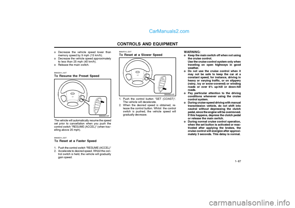
1. Push the control switch "RESUME (ACCEL)"
2. Accelerate to desired speed. Whilst the con- trol switch is held, the vehicle will gradually gain speed.
B660D01L-AAT To Resume the Preset Speed
The vehicle will automatically resume the speed
set prior to cancellation when you push the control switch "RESUME (ACCEL)" (when trav-elling above 25 mph).
B660D01HP
B660F01L-EAT To Reset at a Slower Speed
B660B01HP
1. Push the control button "SET (COAST)". The vehicle will decelerate.
2. When the desired speed is obtained, re- lease the control button. Whilst the control switch is pushed, the vehicle speed willgradually decrease.
o Decrease the vehicle speed lower than
memory speed by 9 mph (15 km/h).
o Decrease the vehicle speed approximately to less than 25 mph (40 km/h).
o Release the main switch.
Page 268 of 361
CONTROLS AND EQUIPMENT
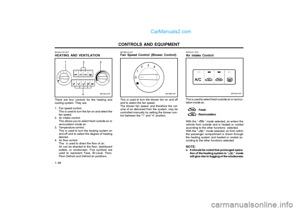
1- 68 B670B01A-AAT Fan Speed Control (Blower Control) This is used to turn the blower fan on and off
and to select the fan speed.
The blower fan speed, and therefore the vol-
ume of air delivered from the system, may be controlled manually by setting the blower con-trol between the "1" and "4" position.
B670A01HP-EAT HEATING AND VENTILATION There are four controls for the heating and
cooling system. They are:
1. Fan speed control. This is used to turn the fan on and select the fan speed.
2. Air intake control. This allows you to select fresh outside air orrecirculation inside air.
3. Temperature control. This is used to turn the heating system onand off and to select the degree of heatingdesired.
4. Air flow control. This is used to direct the flow of air. Air can be directed to the floor, dashboard outlets, or windscreen. Five symbols areused to represent Face, Bi-Level, Floor,Floor-Defrost and Defrost air positions. B670C01Y-EAT Air Intake Control
This is used to select fresh outside air or recircu- lation inside air. Fresh Recirculation
With the " " mode selected, air enters the vehicle from outside and is heated or cooledaccording to the other functions selected. With the " " mode selected, air from within the passenger compartment is drawn throughthe heating system and heated or cooled ac-cording to the other functions selected. NOTE:
o It should be noted that prolonged opera- tion of the heating system in " " mode will give rise to fogging of the windscreen
B670B01HPB670C01HPB670A01HP
2
3
1
4
Page 269 of 361
CONTROLS AND EQUIPMENT1- 69
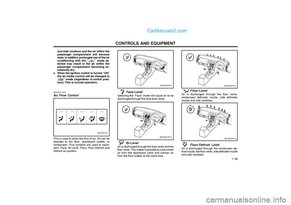
Floor-Level
Air is discharged through the floor vents, windscreen defroster nozzle, side defrosternozzle and side ventilator.
Floor-Defrost Level
Air is discharged through the windscreen de- frost nozzle, the floor vents, side defroster nozzleand side ventilator.
B670D04HP-D
B670D05HP-D
and side windows and the air within the passenger compartment will becomestale. In addition prolonged use of the airconditioning with the " " mode se-lected may result in the air within thepassenger compartment becoming ex-cessively dry.
o When the ignition switch is turned "ON" the air intake control will be changed to" " mode (regardless of switch posi-tion). This is normal operation.
B670D01L-EAT Air Flow Control
B670D01HP
This is used to direct the flow of air. Air can be
directed to the floor, dashboard outlets, or windscreen. Five symbols are used to repre-sent Face, Bi-Level, Floor, Floor-Defrost andDefrost air position. Face-Level
Selecting the "Face" mode will cause air to bedischarged through the face level vents.
Bi-Level
Air is discharged through the face vents and the floor vents. This makes it possible to have coolerair from the dashboard vents and warmer airfrom the floor outlets at the same time.
B670D02HP-D
B670D03HP-D
Page 270 of 361
CONTROLS AND EQUIPMENT
1- 70
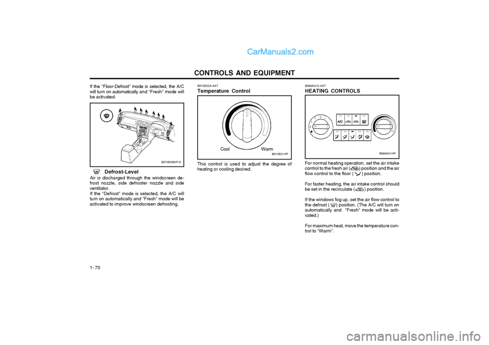
If the "Floor-Defrost" mode is selected, the A/C will turn on automatically and "Fresh" mode will
be activated. B670E02A-AAT Temperature Control
B670D06HP-DThis control is used to adjust the degree of
heating or cooling desired.
Defrost-Level
Air is discharged through the windscreen de-
frost nozzle, side defroster nozzle and side ventilator.
If the "Defrost" mode is selected, the A/C will
turn on automatically and "Fresh" mode will beactivated to improve windscreen defrosting. B690A01S-AAT HEATING CONTROLS
For normal heating operation, set the air intake control to the fresh air ( ) position and the airflow control to the floor ( ) position. For faster heating, the air intake control should be set in the recirculate ( ) position. If the windows fog up, set the air flow control to the defrost ( ) position. (The A/C will turn onautomatically and "Fresh" mode will be acti-vated.) For maximum heat, move the temperature con- trol to "Warm".
B670E01HP
Cool WarmB690A01HP