Hyundai Terracan 2006 Owner's Manual
Manufacturer: HYUNDAI, Model Year: 2006, Model line: Terracan, Model: Hyundai Terracan 2006Pages: 539, PDF Size: 18.11 MB
Page 391 of 539
1
CONTROLS AND EQUIPMENT
83
o Automotive fuels are flammable/ explosive materials. When refuel- ing, please note the followingguidelines carefully. Failure to follow these guidelines may re- sult in severe personal injury, se-vere burns or death by fire or explosion.
- Before refueling always note the
location of the Emergency Fuel Shut-Off, if available, at the fuel station facility.
- Before touching the fuel nozzle or fuel filler cap, you shouldeliminate potentially dangerousstatic electricity discharge by touching another metal part of the front of the vehicle, a safedistance away from the fuel filler neck, nozzle, or other fuel source.
- Do not get back into a vehicle once you have begun refueling.Do not touch, rub or slide againstany item or fabric (polyester, satin, nylon, etc.) capable of pro- ducing static electricity. Staticelectricity discharge can ignite fuel vapors resulting in explo sion.If you must re-enter the vehicle, you should once again elimi-nate potentially dangerous static electricity discharge by touch- ing a metal part of the vehicle,away from the fuel filler neck, nozzle or other fuel source.
- When using a portable fuel con- tainer be sure to place the con-tainer on the ground prior to refueling. Static electricity dis-charge from the container can ignite fuel vapors causing a fire. Once refueling has begun, con-tact with the vehicle should be maintained until the filling is complete. Use only portable fuelcontainers designed to carry and store fuel.
- Do not use cellular phones
around a fuel station or whilstrefueling any vehicle. Electric current and/or electronic inter-ference from cellular phones can potentially ignite fuel vapors causing a fire. If you must useyour cellular phone use it in a place away from the fuel station.
- When refueling always shut theengine off. Sparks produced by electrical components related to the engine can ignite fuel va- pors causing a fire. Always in-sure that the engine is OFF be- fore and during refueling. Once refueling is complete, check tomake sure the fuel filler cap and door are securely closed, before starting the engine.
- Do not light any fire around a fuel station. DO NOT use matchesor a lighter and DO NOT SMOKEor leave a lit cigarette in your vehicle whilst at a gas station especially during refueling.Automotive fuel is highly flam- mable and can, when ignited, result in explosion by flames.
- If a fire breaks out during refuel- ing, leave the vicinity of the ve-hicle, and immediately contactthe manager of the fuel station or contact the police and local fire department. Follow anysafety instructions they provide.
Page 392 of 539
1CONTROLS AND EQUIPMENT
84SUN VISOR
HHP2017-1
!
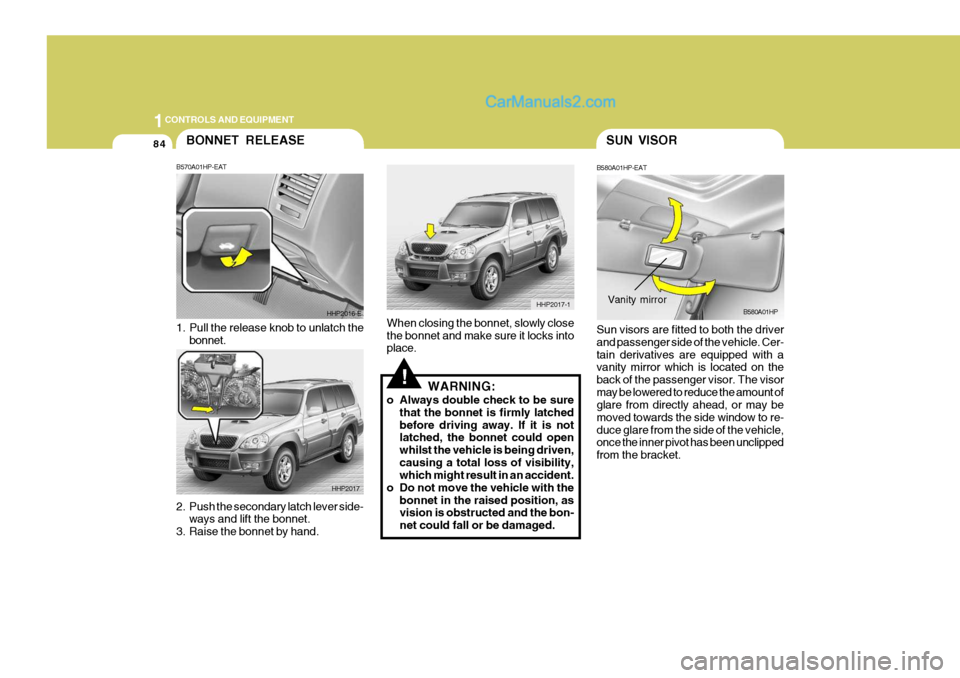
When closing the bonnet, slowly close the bonnet and make sure it locks into place.
WARNING:
o Always double check to be sure that the bonnet is firmly latched before driving away. If it is not latched, the bonnet could open whilst the vehicle is being driven,causing a total loss of visibility, which might result in an accident.
o Do not move the vehicle with the bonnet in the raised position, asvision is obstructed and the bon- net could fall or be damaged. B580A01HP-EAT Sun visors are fitted to both the driver and passenger side of the vehicle. Cer-tain derivatives are equipped with a vanity mirror which is located on the back of the passenger visor. The visormay be lowered to reduce the amount of glare from directly ahead, or may be moved towards the side window to re-duce glare from the side of the vehicle, once the inner pivot has been unclipped from the bracket.
B580A01HPVanity mirror
BONNET RELEASE
2. Push the secondary latch lever side-
ways and lift the bonnet.
3. Raise the bonnet by hand.
B570A01HP-EAT
1. Pull the release knob to unlatch the
bonnet. HHP2016-E
HHP2017
Page 393 of 539
1
CONTROLS AND EQUIPMENT
85
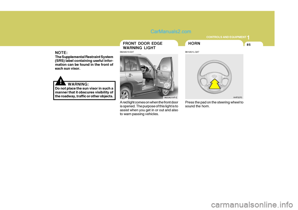
A red light comes on when the front door is opened. The purpose of this light is to assist when you get in or out and also to warn passing vehicles.FRONT DOOR EDGE WARNING LIGHT
B620A01S-EAT
B620A01HP-E
!
NOTE: The Supplemental Restraint System (SRS) label containing useful infor- mation can be found in the front ofeach sun visor.
WARNING:
Do not place the sun visor in such amanner that it obscures visibility ofthe roadway, traffic or other objects.
Press the pad on the steering wheel tosound the horn.
HHP2070
HORN
B610A01L-GAT
Page 394 of 539
1CONTROLS AND EQUIPMENT
86
!
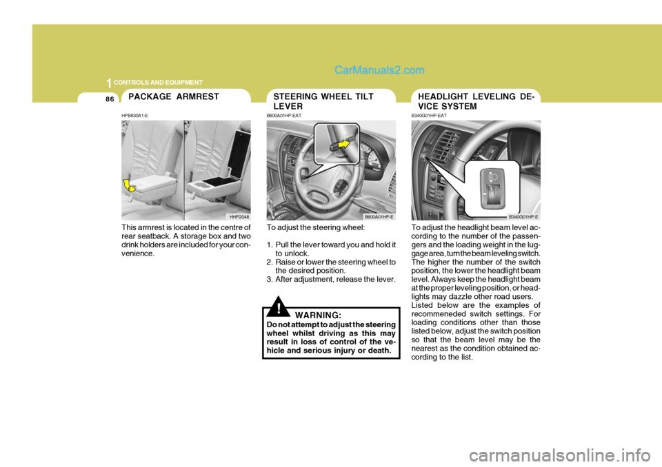
To adjust the steering wheel:
1. Pull the lever toward you and hold it
to unlock.
2. Raise or lower the steering wheel to the desired position.
3. After adjustment, release the lever.
WARNING:
Do not attempt to adjust the steering wheel whilst driving as this may result in loss of control of the ve- hicle and serious injury or death. To adjust the headlight beam level ac-cording to the number of the passen- gers and the loading weight in the lug- gage area, turn the beam leveling switch.The higher the number of the switch position, the lower the headlight beam level. Always keep the headlight beamat the proper leveling position, or head- lights may dazzle other road users. Listed below are the examples ofrecommeneded switch settings. For loading conditions other than those listed below, adjust the switch positionso that the beam level may be the nearest as the condition obtained ac- cording to the list.
STEERING WHEEL TILT LEVER
B600A01HP-EAT
B600A01HP-E
HEADLIGHT LEVELING DE- VICE SYSTEM
B340G01HP-EAT
B340G01HP-E
This armrest is located in the centre of rear seatback. A storage box and two drink holders are included for your con- venience.
PACKAGE ARMREST
HPB830A1-E
HHP2048
Page 395 of 539
1
CONTROLS AND EQUIPMENT
87
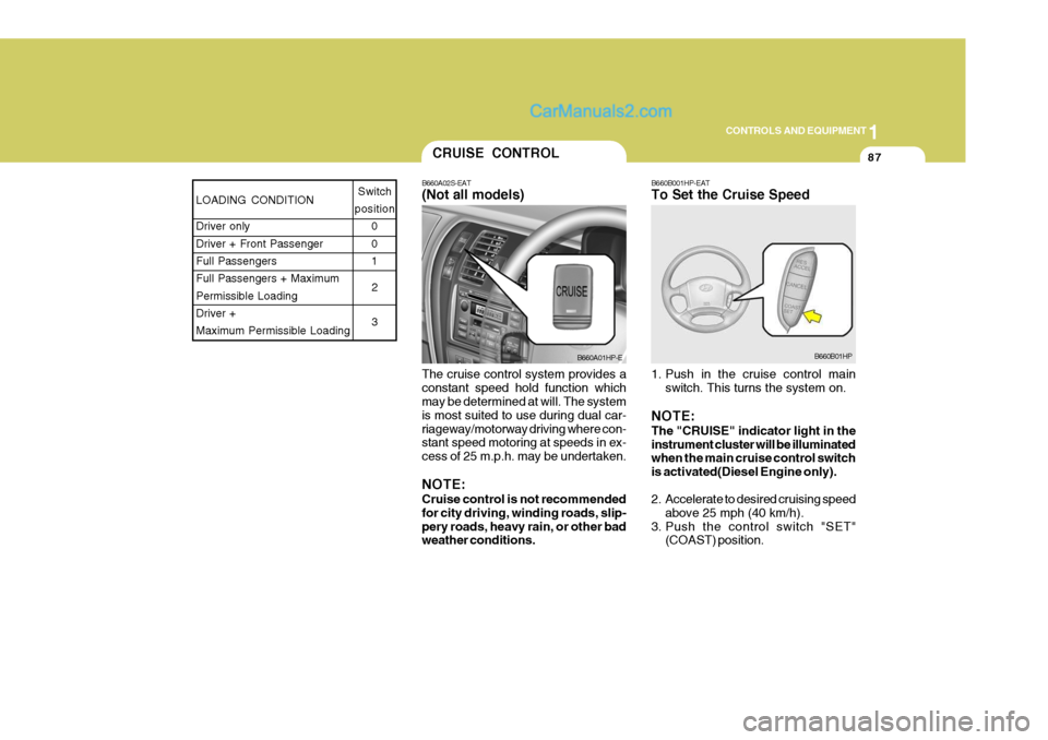
The cruise control system provides a constant speed hold function which may be determined at will. The system is most suited to use during dual car-riageway/motorway driving where con- stant speed motoring at speeds in ex- cess of 25 m.p.h. may be undertaken. NOTE: Cruise control is not recommended for city driving, winding roads, slip-pery roads, heavy rain, or other bad weather conditions.CRUISE CONTROL
B660A02S-EAT (Not all models)
B660A01HP-E
LOADING CONDITION Driver only Driver + Front PassengerFull Passengers Full Passengers + Maximum Permissible LoadingDriver + Maximum Permissible Loading Switch
position 0 01
2 3
B660B001HP-EAT To Set the Cruise Speed
1. Push in the cruise control main switch. This turns the system on.
NOTE: The "CRUISE" indicator light in the instrument cluster will be illuminated when the main cruise control switch is activated(Diesel Engine only).
2. Accelerate to desired cruising speed above 25 mph (40 km/h).
3. Push the control switch "SET" (COAST) position.
B660B01HP
Page 396 of 539
1CONTROLS AND EQUIPMENT
88
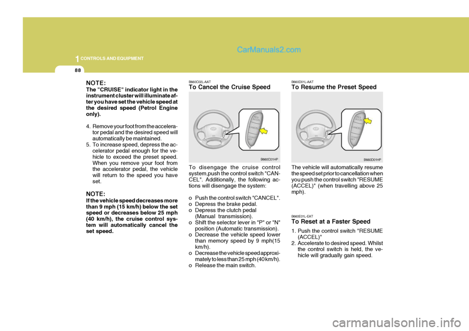
B660C02L-AAT To Cancel the Cruise Speed To disengage the cruise control system,push the control switch "CAN- CEL". Additionally, the following ac- tions will disengage the system:
o Push the control switch "CANCEL".
o Depress the brake pedal.
o Depress the clutch pedal(Manual transmission).
o Shift the selector lever in "P" or "N" position (Automatic transmission).
o Decrease the vehicle speed lower
than memory speed by 9 mph(15km/h).
o Decrease the vehicle speed approxi-
mately to less than 25 mph (40 km/h).
o Release the main switch.
B660C01HP B660D01L-AAT To Resume the Preset Speed The vehicle will automatically resume the speed set prior to cancellation when you push the control switch "RESUME (ACCEL)" (when travelling above 25mph). B660E01L-EAT To Reset at a Faster Speed
1. Push the control switch "RESUME
(ACCEL)"
2. Accelerate to desired speed. Whilst the control switch is held, the ve- hicle will gradually gain speed.B660D01HP
NOTE: The "CRUISE" indicator light in the instrument cluster will illuminate af- ter you have set the vehicle speed atthe desired speed (Petrol Engine only).
4. Remove your foot from the accelera-
tor pedal and the desired speed will automatically be maintained.
5. To increase speed, depress the ac- celerator pedal enough for the ve-hicle to exceed the preset speed.When you remove your foot from the accelerator pedal, the vehicle will return to the speed you haveset.
NOTE: If the vehicle speed decreases more than 9 mph (15 km/h) below the set speed or decreases below 25 mph (40 km/h), the cruise control sys-tem will automatically cancel the set speed.
Page 397 of 539
1
CONTROLS AND EQUIPMENT
89
!
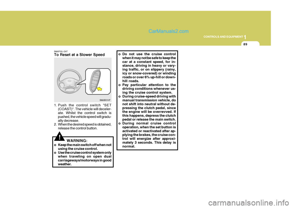
B660F02L-EAT To Reset at a Slower Speed
1. Push the control switch "SET
(COAST)". The vehicle will deceler- ate. Whilst the control switch is pushed, the vehicle speed will gradu-ally decrease.
2. When the desired speed is obtained,
release the control button. o Do not use the cruise control
when it may not be safe to keep thecar at a constant speed, for in- stance, driving in heavy or vary- ing traffic, or on slippery (rainy,icy or snow-covered) or winding roads or over 6% up-hill or down- hill roads.
o Pay particular attention to the driving conditions whenever us-ing the cruise control system.
o During cruise-speed driving with manual transmission vehicle, donot shift into neutral without de-pressing the clutch pedal, since the engine will be overrevved. If this happens, depress the clutchpedal or release the main switch.
o During normal cruise control
operation, when the set button isactivated or reactivated after ap- plying the brakes, the cruise con- trol will energize after approxi-mately 3 seconds. This delay is normal.
WARNING:
o Keep the main switch off when not using the cruise control.
o Use the cruise control system only when traveling on open dual carriageways/motorways in goodweather.
B660B01HP
Page 398 of 539
1CONTROLS AND EQUIPMENT
90
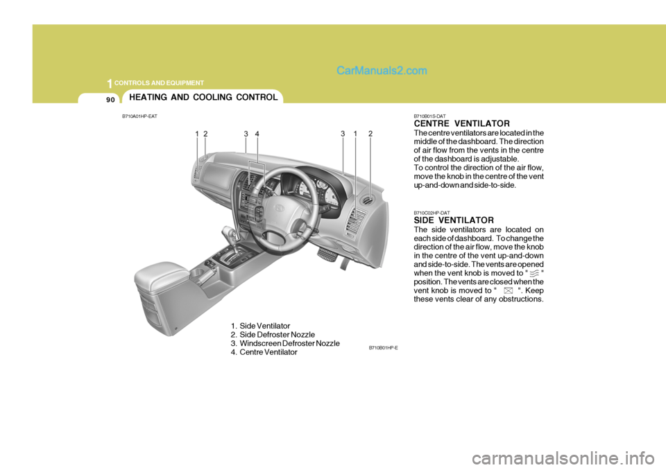
B710B01S-DAT CENTRE VENTILATOR The centre ventilators are located in the middle of the dashboard. The direction of air flow from the vents in the centreof the dashboard is adjustable. To control the direction of the air flow, move the knob in the centre of the ventup-and-down and side-to-side. B710C02HP-DAT SIDE VENTILATOR The side ventilators are located on each side of dashboard. To change the direction of the air flow, move the knob in the centre of the vent up-and-downand side-to-side. The vents are opened when the vent knob is moved to " " position. The vents are closed when thevent knob is moved to " ". Keep these vents clear of any obstructions.
HEATING AND COOLING CONTROL
B710A01HP-EAT
1. Side Ventilator
2. Side Defroster Nozzle
3. Windscreen Defroster Nozzle
4. Centre Ventilator B710B01HP-E
Page 399 of 539
1
CONTROLS AND EQUIPMENT
91
B670B01A-AAT Fan Speed Control (Blower Control)
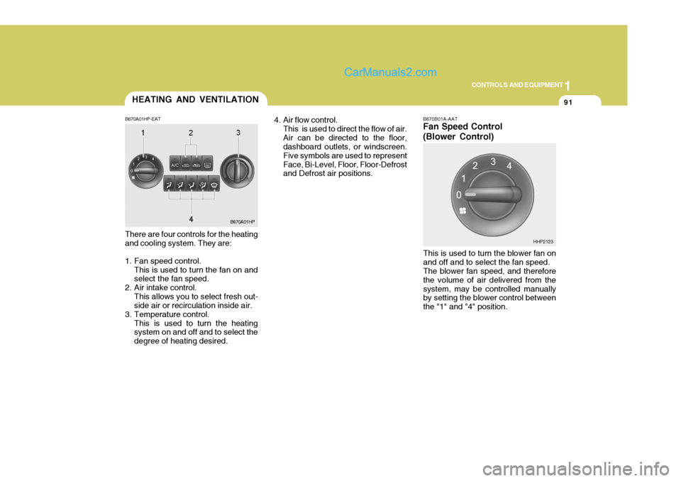
There are four controls for the heating and cooling system. They are:
1. Fan speed control. This is used to turn the fan on and select the fan speed.
2. Air intake control. This allows you to select fresh out-side air or recirculation inside air.
3. Temperature control. This is used to turn the heatingsystem on and off and to select the degree of heating desired. 4. Air flow control.
This is used to direct the flow of air.Air can be directed to the floor, dashboard outlets, or windscreen. Five symbols are used to representFace, Bi-Level, Floor, Floor-Defrost and Defrost air positions.
This is used to turn the blower fan on and off and to select the fan speed. The blower fan speed, and therefore the volume of air delivered from thesystem, may be controlled manually by setting the blower control between the "1" and "4" position.
B670A01HP
HHP2123
HEATING AND VENTILATION
B670A01HP-EAT
Page 400 of 539
1CONTROLS AND EQUIPMENT
92
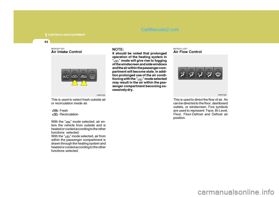
B670C02Y-EAT Air Intake Control This is used to select fresh outside air or recirculation inside air.
Fresh
Recirculation
With the "
" mode selected, air en-
ters the vehicle from outside and is heated or cooled according to the other functions selected. With the "
" mode selected, air from
within the passenger compartment is drawn through the heating system and heated or cooled according to the otherfunctions selected. NOTE: It should be noted that prolonged operation of the heating system in "
" mode will give rise to fogging
of the windscreen and side windows and the air within the passenger com- partment will become stale. In addi-tion prolonged use of the air condi- tioning with the "
" mode selected
may result in the air within the pas- senger compartment becoming ex- cessively dry. B670D01L-EAT Air Flow Control This is used to direct the flow of air. Air can be directed to the floor, dashboard outlets, or windscreen. Five symbols are used to represent Face, Bi-Level,Floor, Floor-Defrost and Defrost air position.
HHP2125HHP2126