AUTOMATIC DRIVE POSITIONER
SE-81
C
D
E
F
G
H
J
K
L
MA
B
SE
Revision: 2004 November 2004 FX35/FX45
2. CHECK HARNESS CONTINUITY
1. Turn ignition switch OFF.
2. Disconnect automatic drive positioner control unit and door mirror remote control switch connector.
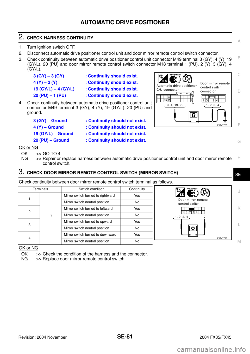
3. Check continuity between automatic drive positioner control unit connector M49 terminal 3 (GY), 4 (Y), 19
(GY/L), 20 (PU) and door mirror remote control switch connector M18 terminal 1 (PU), 2 (Y), 3 (GY), 4
(GY/L).
4. Check continuity between automatic drive positioner control unit
connector M49 terminal 3 (GY), 4 (Y), 19 (GY/L), 20 (PU) and
ground.
OK or NG
OK >> GO TO 4.
NG >> Repair or replace harness between automatic drive positioner control unit and door mirror remote
control switch.
3. CHECK DOOR MIRROR REMOTE CONTROL SWITCH (MIRROR SWITCH)
Check continuity between door mirror remote control switch terminal as follows.
OK or NG
OK >> Check the condition of the harness and the connector.
NG >> Replace door mirror remote control switch.3 (GY) – 3 (GY) : Continuity should exist.
4 (Y) – 2 (Y) : Continuity should exist.
19 (GY/L) – 4 (GY/L) : Continuity should exist.
20 (PU) – 1 (PU) : Continuity should exist.
3 (GY) – Ground : Continuity should not exist.
4 (Y) – Ground : Continuity should not exist.
19 (GY/L) – Ground : Continuity should not exist.
20 (PU) – Ground : Continuity should not exist.
PIIA4772E
Terminals Switch condition Continuity
1
7Mirror switch turned to rightward Yes
Mirror switch neutral position No
2Mirror switch turned to leftward Yes
Mirror switch neutral position No
3Mirror switch turned to upward Yes
Mirror switch neutral position No
4Mirror switch turned to downward Yes
Mirror switch neutral position No
PIIA4773E
REAR SEAT
SE-109
C
D
E
F
G
H
J
K
L
MA
B
SE
Revision: 2004 November 2004 FX35/FX45
REMOVAL
1. Pull the lock at the front bottom of the seat cushion forward (1
for each side), and pull the seat cushion upward to release the
wire from the plastic hook, then pull the seat cushion forward to
remove.
2. Remove the seatback mounting nuts.
3. Remove the seatback mounting bolt and nut.
Remove the remote control wire.
INSTALLATION
Install in the reverse order of removal.
NOTE:
After rear wheel house finisher assembly is remove the seatback is installed. Refer to EI-44, "
Removal and
Installation" .
REMOVAL OF SEAT CUSHION TRIM AND PAD
1. Remove the cup holder in the back of the seat cushion.
2. Removal the hog rings to separate the trim and pad.
PIIA6034E
PIIA6035E
PIIA6036E
PIIA4985E
REAR SEAT
SE-111
C
D
E
F
G
H
J
K
L
MA
B
SE
Revision: 2004 November 2004 FX35/FX45
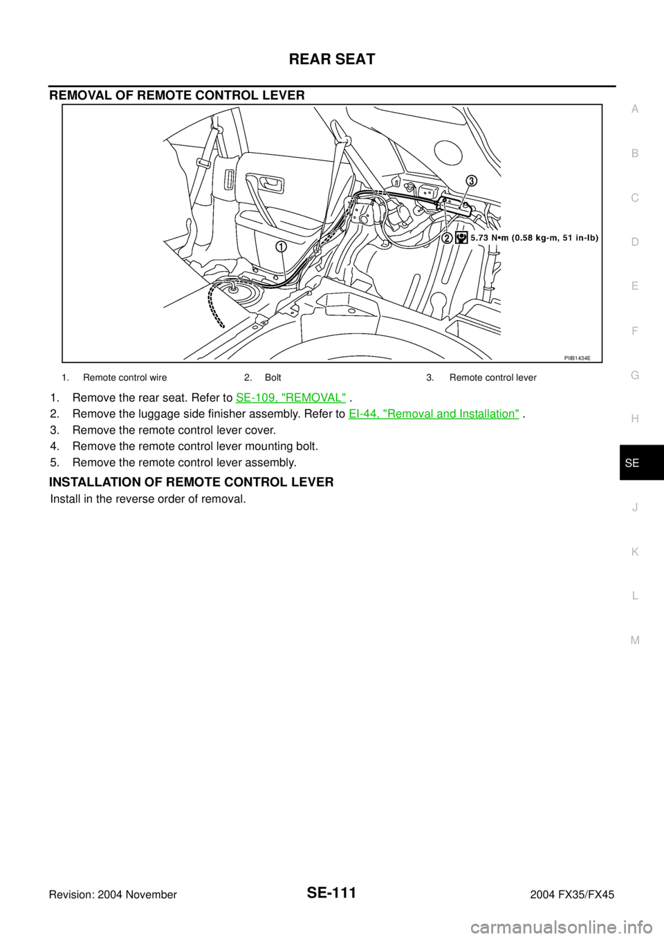
REMOVAL OF REMOTE CONTROL LEVER
1. Remove the rear seat. Refer to SE-109, "REMOVAL" .
2. Remove the luggage side finisher assembly. Refer to EI-44, "
Removal and Installation" .
3. Remove the remote control lever cover.
4. Remove the remote control lever mounting bolt.
5. Remove the remote control lever assembly.
INSTALLATION OF REMOTE CONTROL LEVER
Install in the reverse order of removal.
PIIB1434E
1. Remote control wire 2. Bolt 3. Remote control lever


