service indicator INFINITI FX35 2008 Owners Manual
[x] Cancel search | Manufacturer: INFINITI, Model Year: 2008, Model line: FX35, Model: INFINITI FX35 2008Pages: 3924, PDF Size: 81.37 MB
Page 1208 of 3924
![INFINITI FX35 2008 Owners Manual
DI-82
< SERVICE INFORMATION >
LANE DEPARTURE WARNING SYSTEM
NOTE:
When a DTC is detected, the LDW system dose not operate.
When the DTC except “ABNRML TEMP DETECT [C1B03] ” is detected, the INFINITI FX35 2008 Owners Manual
DI-82
< SERVICE INFORMATION >
LANE DEPARTURE WARNING SYSTEM
NOTE:
When a DTC is detected, the LDW system dose not operate.
When the DTC except “ABNRML TEMP DETECT [C1B03] ” is detected, the](/img/42/57017/w960_57017-1207.png)
DI-82
< SERVICE INFORMATION >
LANE DEPARTURE WARNING SYSTEM
NOTE:
When a DTC is detected, the LDW system dose not operate.
When the DTC except “ABNRML TEMP DETECT [C1B03] ” is detected, the LDW indicator lamp turns ON.
When the DTC “ABNRML TEMP DETECT [C1B03] ” is detected, the LDW system ON indicator lamp blinks.
DATA MONITOR
Display Item
ACTIVE TEST
CAUTION:
Never perform the active test while driving.
Active test cannot be started while LDW indicator lamp is illuminated.
Display item [Code] Malfunctions detected where... Reference
page
CAMERA UNIT MALF [C1B00] LDW camera unit internal malfunction DI-85
CAM AIMING INCMP [C1B01] LDW camera aiming is not adjusted. DI-85
VHCL SPD DATA MALF [C1B02]LDW camera unit detected different vehicle speed signal from TCM and ABS ac-
tuator and electric unit (control unit). DI-85
ABNRML TEMP DETECT [C1B03] Temperature around LDW camera unit is excessively high.
DI-86
CAN COMM CIRCUIT [U1000] LDW camera unit detected CAN communication malfunction. DI-86
CONTROL UNIT (CAN) [U1010] LDW camera unit detected internal CAN communication circuit malfunction. DI-86
Monitored Item [unit] Description
VHCL SPD SE [km/h] or [mph] Displays vehicle speed calculated by LDW camera unit through CAN communication [ABS
actuator and electric unit (control unit) transmits wheel sensor signal through CAN communi-
cation].
VHCL SPD AT [km/h] or [mph] Displays vehicle speed calculated from A/T vehicle speed sensor by LDW camera unit
through CAN communication (TCM transmits A/T vehicle speed sensor signal through CAN
communication).
FCTRY AIM YAW [deg] Displays camera unit installation condition.
FCTRY AIM ROL [deg] Displays camera unit installation condition.
FCTRY AIM PIT [deg] Displays camera unit installation condition.
XOFFSET [pixel] Displays camera unit installation condition.
MAIN SW [On/Off] Displays [On/Off] status as judged from LDW switch signal.
SW ON LAMP [On/Off] Displays [On/Off] status of LDW system ON indicator signal output.
INDICATE LAMP [On/Off] Displays [On/Off] status of LDW indicator signal output.
BUZZER OUTPUT [On/Off] Displays [On/Off] status of LDW chime operation signal output.
LDW INACCURAT [On/Off] Displays LDW camera unit status.
TURN SIGNAL [Off/LH/RH] Displays “Tur n signal” status, determined from BCM thro ugh CAN communication.
LANE DETCT LH [On/Off] Displays left lane marker is detected.
LANE DETCT RH [On/Off] Displays right lane marker is detected.
CROSS LANE LH [On/Off] Displays vehicle is crossing left lane.
CROSS LANE RH [On/Off] Displays vehicle is crossing right lane.
WARN LANE LH [On/Off] Displays warning for left lane.
WARN LANE RH [On/Off] Displays warning for right lane.
VALID POS LH [VLD/INVLD] Displays lateral position for left lane marker is valid.
VALID POS RH [VLD/INVLD] Displays lateral position for right lane marker is valid.
AIMING DONE [OK/NG] Displa ys camera aiming done.
AIMING RESULT [OK/NOK] Disp lays camera aiming result.
3AA93ABC3ACD3AC03ACA3AC03AC63AC53A913A773A893A873A873A8E3A773A983AC73AC93AC03AC3
3A893A873A873A8F3A773A9D3AAF3A8A3A8C3A863A9D3AAF3A8B3A8C
Page 1209 of 3924

LANE DEPARTURE WARNING SYSTEMDI-83
< SERVICE INFORMATION >
C
DE
F
G H
I
J
L
M A
B
DI
N
O P
1. Select “Active Test”.
2. Select any field, “BUZZER DRIVE ”, “SYSTEM ON LAMP DRIVE” and “INDICATOR LAMP DRIVE”, on
selection screen.
3. Select necessary item and “Start”.
4. Active test screen will be shown.
Display Item
BUZZER DRIVE
Select “On” and “Off” to check if LDW chime operates as follows.
SYSTEM ON LAMP DRIVE
Select “ON” and “OFF” to check if LDW s ystem ON indicator operates as follows.
NOTE:
Perform “SYSTEM ON LAMP DRIVE” when LDW system ON indicator turns OFF.
INDICATOR LAMP DRIVE
Select “On” and “Off” to check that LDW indicator lamp operates as follows.
Trouble DiagnosisINFOID:0000000001328501
HOW TO PERFORM TROUBLE DIAGNOSIS
1. Check the symptom and customer complaint.
2. Understand the outline of system. Refer to DI-69, "
System Description".
3. Perform the preliminary inspection. Refer to DI-84, "
Preliminary Check".
4. Referring to symptom chart, repair or replace the cause of the malfunction. Refer to "SYMPTOM CHART".
5. Erase DTC and perform self-diagnosis of LDW sys tem again. Then perform LDW system running test.
Refer to DI-81, "
CONSULT-III Function (LDW)" and DI-71, "Action Test".
6. Does LDW system operate normally? If it oper ates normally, GO TO 7. If not, GO TO 3.
7. INSPECTION END
SYMPTOM CHART
Active test item Operation item Function
BUZZER DRIVE LDW chime This test is able to check LDW chime operation.
SYSTEM ON LAMP DRIVE LDW system ON indicator This test is able to check LDW system ON indicator operation.
INDICATOR LAMP DRIVE LDW indicator lamp This test is able to check LDW indicator lamp operation.
“BUZZER DRIVE”
Select “On” : LDW chime is activated.
Select “Off” : LDW chime is not activated.
“SYSTEM ON LAMP DRIVE”
Select “On” : LDW system ON indicator illuminates.
Select “Off” : LDW system ON indicator turns OFF.
“INDICATOR LAMP DRIVE”
Select “On” : LDW indicator lamp illuminates.
Select “Off” : LDW indicator lamp OFF.
3AA93ABC3ACD3AC03ACA3AC03AC63AC53A913A773A893A873A873A8E3A773A983AC73AC93AC03AC3
3A893A873A873A8F3A773A9D3AAF3A8A3A8C3A863A9D3AAF3A8B3A8C
Page 1210 of 3924
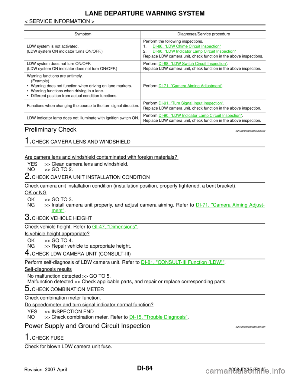
DI-84
< SERVICE INFORMATION >
LANE DEPARTURE WARNING SYSTEM
Preliminary Check
INFOID:0000000001328502
1.CHECK CAMERA LENS AND WINDSHIELD
Are camera lens and windshield contaminated with foreign materials?
YES >> Clean camera lens and windshield.
NO >> GO TO 2.
2.CHECK CAMERA UNIT IN STALLATION CONDITION
Check camera unit installation condition (installat ion position, properly tightened, a bent bracket).
OK or NG
OK >> GO TO 3.
NG >> Install camera unit properly, and adjust camera aiming. Refer to DI-71, "
Camera Aiming Adjust-
ment".
3.CHECK VEHICLE HEIGHT
Check vehicle height. Refer to GI-47, "
Dimensions".
Is vehicle height appropriate?
OK >> GO TO 4.
NG >> Repair vehicle to appropriate height.
4.CHECK LDW CAMERA UNIT (CONSULT-III)
Perform self-diagnosis of LDW camera unit. Refer to DI-81, "
CONSULT-III Function (LDW)".
Self
-diagnosis results
No malfunction detected >> GO TO 5.
Malfunction detected >> Check applicable parts, and repair or replace corresponding parts.
5.CHECK COMBINATION METER
Check combination meter function.
Do speedometer and turn signal indicator normal function?
YES >> INSPECTION END
NO >> Check combination meter. Refer to DI-15, "
Trouble Diagnosis".
Power Supply and Ground Circuit InspectionINFOID:0000000001328503
1.CHECK FUSE
Check for blown LDW camera unit fuse.
Symptom Diagnoses/Service procedure
LDW system is not activated.
(LDW system ON indicator turns ON/OFF.) Perform the following inspections.
1.
DI-86, "
LDW Chime Circuit Inspection"
2.DI-90, "LDW Indicator Lamp Circuit Inspection"
Replace LDW camera unit, check function in the above inspections.
LDW system does not turn ON/OFF.
(LDW system ON indicator does not turn ON/OFF.) Perform
DI-88, "
LDW Switch Circuit Inspection".
Replace LDW camera unit, check function in the above inspection.
Warning functions are untimely. (Example)
Warning does not function when driving on lane markers.
Warning functions when driving in a lane.
Different position from actual condition functions. Perform
DI-71, "
Camera Aiming Adjustment".
Functions when changing the course to the turn signal direction. Perform
DI-91, "
Turn Signal Input Inspection".
Replace LDW camera unit, check function in the above inspection.
LDW indicator lamp does not illuminate with ignition switch ON. Perform
DI-90, "
LDW Indicator Lamp Circuit Inspection".
Replace LDW camera unit, check function in the above inspection.
3AA93ABC3ACD3AC03ACA3AC03AC63AC53A913A773A893A873A873A8E3A773A983AC73AC93AC03AC3
3A893A873A873A8F3A773A9D3AAF3A8A3A8C3A863A9D3AAF3A8B3A8C
Page 1214 of 3924
DI-88
< SERVICE INFORMATION >
LANE DEPARTURE WARNING SYSTEM
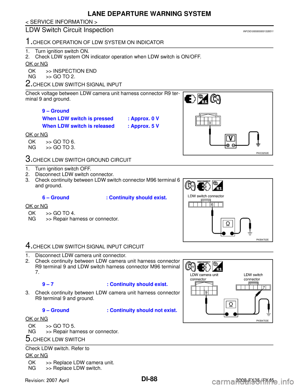
LDW Switch Circuit Inspection
INFOID:0000000001328511
1.CHECK OPERATION OF LDW SYSTEM ON INDICATOR
1. Turn ignition switch ON.
2. Check LDW system ON indicator operation when LDW switch is ON/OFF.
OK or NG
OK >> INSPECTION END
NG >> GO TO 2.
2.CHECK LDW SWITCH SIGNAL INPUT
Check voltage between LDW camera unit harness connector R9 ter-
minal 9 and ground.
OK or NG
OK >> GO TO 6.
NG >> GO TO 3.
3.CHECK LDW SWITCH GROUND CIRCUIT
1. Turn ignition switch OFF.
2. Disconnect LDW switch connector.
3. Check continuity between LDW switch connector M96 terminal 6 and ground.
OK or NG
OK >> GO TO 4.
NG >> Repair harness or connector.
4.CHECK LDW SWITCH SIGNAL INPUT CIRCUIT
1. Disconnect LDW camera unit connector.
2. Check continuity between LDW camera unit harness connector R9 terminal 9 and LDW switch harness connector M96 terminal
7.
3. Check continuity between LDW camera unit harness connector R9 terminal 9 and ground.
OK or NG
OK >> GO TO 5.
NG >> Repair harness or connector.
5.CHECK LDW SWITCH
Check LDW switch. Refer to
OK or NG
OK >> Replace LDW camera unit.
NG >> Replace LDW switch. 9 – Ground
When LDW switch is pressed : Approx. 0 V
When LDW switch is released : Approx. 5 V
PKIC0252E
6 – Ground : Continuity should exist.
PKIB4702E
9 – 7 : Continuity should exist.
9 – Ground : Continuity should not exist.
PKIB4703E
3AA93ABC3ACD3AC03ACA3AC03AC63AC53A913A773A893A873A873A8E3A773A983AC73AC93AC03AC3
3A893A873A873A8F3A773A9D3AAF3A8A3A8C3A863A9D3AAF3A8B3A8C
Page 1215 of 3924
LANE DEPARTURE WARNING SYSTEMDI-89
< SERVICE INFORMATION >
C
DE
F
G H
I
J
L
M A
B
DI
N
O P
6.CHECK OPERATION OF LDW SYSTEM ON INDICATOR
Check LDW system ON indicator oper ation “SYSTEM ON LAMP DRIVE” in “Active Test” mode with CON-
SULT-III.
NOTE:
Perform “SYSTEM ON LAMP DRIVE” when LDW system ON indicator turns OFF.
OK or NG
OK >> Replace LDW camera unit.
NG >> GO TO 7.
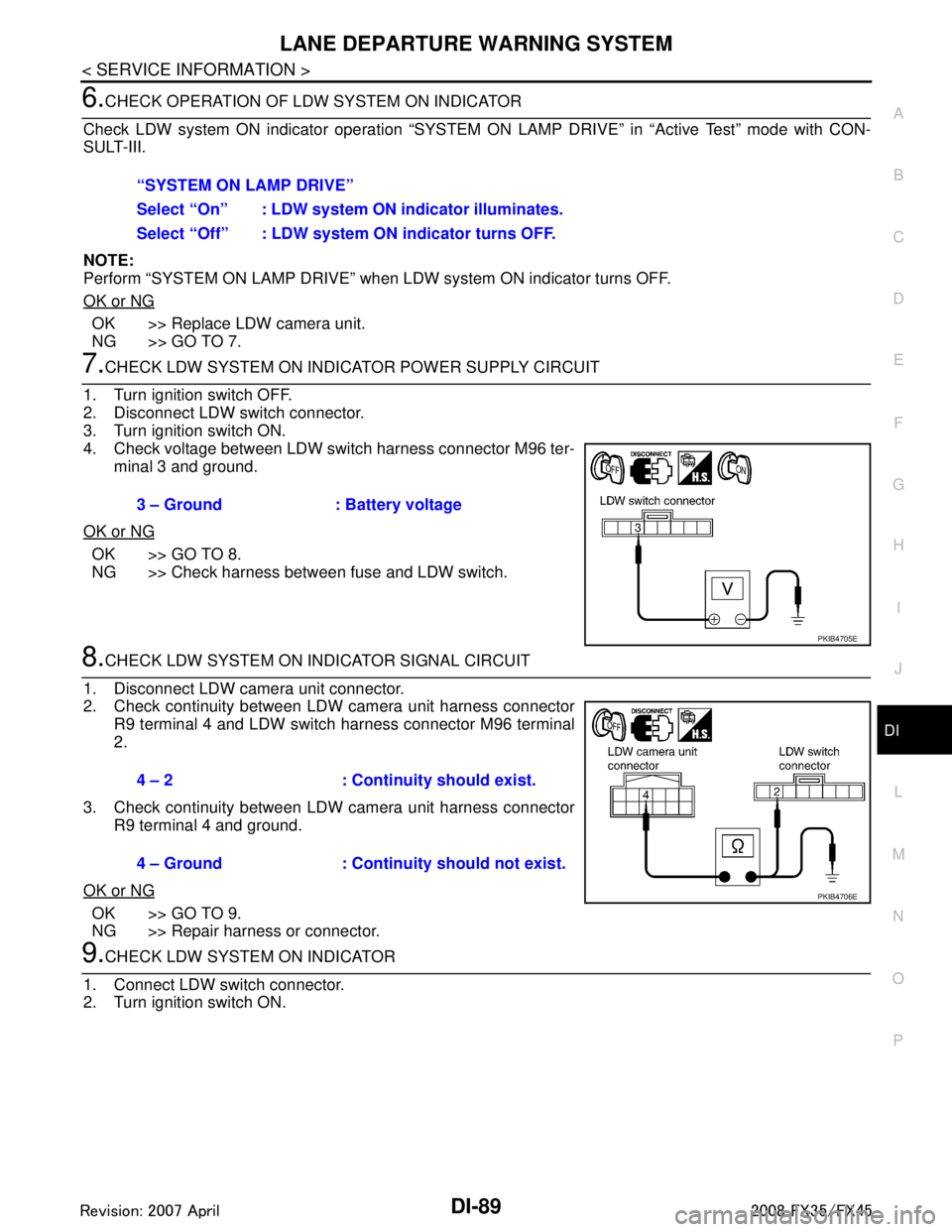
7.CHECK LDW SYSTEM ON INDICATOR POWER SUPPLY CIRCUIT
1. Turn ignition switch OFF.
2. Disconnect LDW switch connector.
3. Turn ignition switch ON.
4. Check voltage between LDW switch harness connector M96 ter- minal 3 and ground.
OK or NG
OK >> GO TO 8.
NG >> Check harness between fuse and LDW switch.
8.CHECK LDW SYSTEM ON INDICATOR SIGNAL CIRCUIT
1. Disconnect LDW camera unit connector.
2. Check continuity between LDW camera unit harness connector R9 terminal 4 and LDW switch harness connector M96 terminal
2.
3. Check continuity between LDW camera unit harness connector R9 terminal 4 and ground.
OK or NG
OK >> GO TO 9.
NG >> Repair harness or connector.
9.CHECK LDW SYSTEM ON INDICATOR
1. Connect LDW switch connector.
2. Turn ignition switch ON. “SYSTEM ON LAMP DRIVE”
Select “On” : LDW system ON
indicator illuminates.
Select “Off” : LDW system ON indicator turns OFF.
3 – Ground : Battery voltage
PKIB4705E
4 – 2 : Continuity should exist.
4 – Ground : Continuity should not exist.
PKIB4706E
3AA93ABC3ACD3AC03ACA3AC03AC63AC53A913A773A893A873A873A8E3A773A983AC73AC93AC03AC3
3A893A873A873A8F3A773A9D3AAF3A8A3A8C3A863A9D3AAF3A8B3A8C
Page 1216 of 3924
DI-90
< SERVICE INFORMATION >
LANE DEPARTURE WARNING SYSTEM
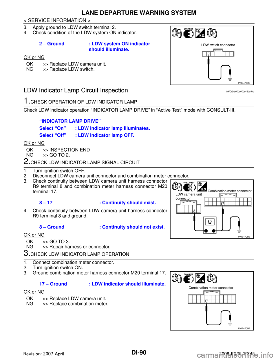
3. Apply ground to LDW switch terminal 2.
4. Check condition of the LDW system ON indicator.
OK or NG
OK >> Replace LDW camera unit.
NG >> Replace LDW switch.
LDW Indicator Lamp Circuit InspectionINFOID:0000000001328512
1.CHECK OPERATION OF LDW INDICATOR LAMP
Check LDW indicator operation “INDICATOR LAMP DR IVE” in “Active Test” mode with CONSULT-III.
OK or NG
OK >> INSPECTION END
NG >> GO TO 2.
2.CHECK LDW INDICATOR LAMP SIGNAL CIRCUIT
1. Turn ignition switch OFF.
2. Disconnect LDW camera unit connector and combination meter connector.
3. Check continuity between LDW camera unit harness connector R9 terminal 8 and combination meter harness connector M20
terminal 17.
4. Check continuity between LDW camera unit harness connector R9 terminal 8 and ground.
OK or NG
OK >> GO TO 3.
NG >> Repair harness or connector.
3.CHECK LDW INDICATOR LAMP OPERATION
1. Connect combination meter connector.
2. Turn ignition switch ON.
3. Ground combination meter harness connector M20 terminal 17.
OK or NG
OK >> Replace LDW camera unit.
NG >> Replace combination meter. 2 – Ground : LDW system ON indicator
should illuminate.
PKIB4707E
“INDICATOR LAMP DRIVE”
Select “On” : LDW indicator lamp illuminates.
Select “Off” : LDW indicator lamp OFF.
8 – 17 : Continuity should exist.
8 – Ground : Continuity should not exist.
PKIB4708E
17 – Ground : LDW indicator should illuminate.
PKIB4709E
3AA93ABC3ACD3AC03ACA3AC03AC63AC53A913A773A893A873A873A8E3A773A983AC73AC93AC03AC3
3A893A873A873A8F3A773A9D3AAF3A8A3A8C3A863A9D3AAF3A8B3A8C
Page 1221 of 3924

COMPASSDI-95
< SERVICE INFORMATION >
C
DE
F
G H
I
J
L
M A
B
DI
N
O P
During normal operation, the Compass Mirror will cont inuously update the compass calibration to adjust for
gradual changes in the vehicle's magnetic “remnant” field. If the vehicle is subjected to high magnetic influ-
ences, the compass may appear to indicate false headings , become locked, or appear that it is unable to be
calibrated. If this occurs, perform the calibration procedure.
If at any time the compass continually displays the inco rrect direction or the reading is erratic or locked, ver-
ify the correct zone variance.
Troubleshooting Chart
Zone Variation Setting ProcedureINFOID:0000000001328523
NOTE:
The zone setting is factory preset (“default” setting) to zone 8.
1. Press and hold the inside mirror switch for 6 – 9 seconds.
2. The current zone setting appears on the compass display.
3. Find the current geographical location number in the Zone Varia-
tion Chart.
4. Select the new zone number. (Press the inside mirror switch until the new zone number appears on the compass display.)
5. After select the new zone number, the compass display will automatically shows a direction within a few seconds.
6. Preform the following Calibration Procedure for more accurate indications.
Calibration ProcedureINFOID:0000000001328524
NOTE:
The compass calibrates itself under normal driving conditions. However, occasional circumstances may cause
the compass to operate inaccurately. Example: Driving from rural (wide open) areas to crowded city areas, or
Symptom Cause Solution / Reference
The compass display reads “C”.
Compass is not calibrated.
Incorrect zone variance setting.
Large change in magnetic field (Steel bridges, subways, concentrations of met-
al, carwashes, etc.)
Compass was calibrated incorrectly or in
the presence of a strong magnetic field. Perform Calibration.
Refer to
DI-95, "
Calibration Procedure".
Compass shows the wrong direction.
Compass does not change direction – ap-
pears “Locked”.
Compass does not show all the directions,
one or more is missing.
The compass was calibrated but it “loses”
calibration.
On long trips the compass shows the wrong
direction.
Perform Zone Variatio
n Setting if correct
reading is desired in that location.
Refer to DI-95, "
Zone Variation Setting Pro-
cedure".
Compass does not work – No direction is
displayed. Compass not turned ON.
Check for green LED indicator (inside mir-
ror switch).
No power to inside mirror. Check power supply circuit.
SEL168Y
3AA93ABC3ACD3AC03ACA3AC03AC63AC53A913A773A893A873A873A8E3A773A983AC73AC93AC03AC3
3A893A873A873A8F3A773A9D3AAF3A8A3A8C3A863A9D3AAF3A8B3A8C
Page 1241 of 3924

EC-1
ENGINE
C
DE
F
G H
I
J
K L
M
SECTION EC
A
EC
N
O P
CONTENTS
ENGINE CONTROL SYSTEM
VQ35DE
SERVICE INFORMATION .. .........................
17
INDEX FOR DTC ............................................ ....17
DTC No. Index .................................................... ....17
Alphabetical Index ...................................................20
PRECAUTIONS ..................................................25
Precaution for Supplemental Restraint System
(SRS) "AIR BAG" and "SEAT BELT PRE-TEN-
SIONER" ............................................................. ....
25
Precaution for Procedure without Cowl Top Cover ....25
On Board Diagnosis (OBD) System of Engine and
A/T ...........................................................................
25
Precaution ...............................................................26
PREPARATION ..................................................29
Special Service Tool ........................................... ....29
Commercial Service Tool ........................................30
ENGINE CONTROL SYSTEM ............................31
Schematic ........................................................... ....31
Multiport Fuel Injection (MFI) System .....................31
Electronic Ignition (EI) System ................................34
Fuel Cut Control (at No Load and High Engine
Speed) .....................................................................
34
AIR CONDITIONING CUT CONTROL ...............36
Input/Output Signal Chart .................................... ....36
System Description .................................................36
AUTOMATIC SPEED CONTROL DEVICE
(ASCD) ...............................................................
37
System Description ............................................. ....37
Component Description ...........................................38
CAN COMMUNICATION ....................................39
System Description ............................................. ....39
EVAPORATIVE EMISSION SYSTEM ................40
Description .......................................................... ....40
Component Inspection ......................................... ....42
Removal and Installation .........................................44
How to Detect Fuel Vapor Leakage .........................44
ON BOARD REFUELING VAPOR RECOV-
ERY (ORVR) ......................................................
46
System Description ..................................................46
Diagnosis Procedure ...............................................46
Component Inspection .............................................48
POSITIVE CRANKCASE VENTILATION .........51
Description ...............................................................51
Component Inspection .............................................51
IVIS (INFINITI VEHICLE IMMOBILIZER SYS-
TEM-NATS) .......................................................
53
Description ...............................................................53
ON BOARD DIAGNOSTIC (OBD) SYSTEM ....54
Introduction ..............................................................54
Two Trip Detection Logic .........................................54
Emission-Related Diagnostic Information ................55
Malfunction Indicator Lamp (MIL) ............................71
OBD System Operation Chart .................................74
BASIC SERVICE PROCEDURE .......................80
Basic Inspection ......................................................80
Idle Speed and Ignition Timing Check .....................84
Procedure After Replacing ECM .............................84
VIN Registration ......................................................84
Accelerator Pedal Released Position Learning .......85
Throttle Valve Closed Position Learning .................85
Idle Air Volume Learning .........................................85
Fuel Pressure Check ...............................................87
TROUBLE DIAGNOSIS ....................................89
Trouble Diagnosis Introduction ................................89
DTC Inspection Priority Chart ..................................93
Fail-Safe Chart ........................................................95
Symptom Matrix Chart .............................................96
Engine Control Component Parts Location ...........100
Vacuum Hose Drawing ..........................................106
3AA93ABC3ACD3AC03ACA3AC03AC63AC53A913A773A893A873A873A8E3A773A983AC73AC93AC03AC3
3A893A873A873A8F3A773A9D3AAF3A8A3A8C3A863A9D3AAF3A8B3A8C
Page 1248 of 3924

EC-8
Component Inspection ...........................................545
ASCD INDICATOR ..........................................547
Component Description ....................................... ..547
CONSULT-III Reference Value in Data Monitor
Mode .................................................................... ..
547
Wiring Diagram ......................................................548
Diagnosis Procedure .............................................548
ELECTRICAL LOAD SIGNAL .........................550
Description ........................................................... ..550
CONSULT-III Reference Value in Data Monitor
Mode .................................................................... ..
550
Diagnosis Procedure .............................................550
FUEL INJECTOR .............................................552
Component Description ....................................... ..552
CONSULT-III Reference Value in Data Monitor
Mode .................................................................... ..
552
Wiring Diagram ......................................................553
Diagnosis Procedure .............................................554
Component Inspection ...........................................557
Removal and Installation .......................................557
FUEL PUMP .....................................................558
Description ........................................................... ..558
CONSULT-III Reference Value in Data Monitor
Mode .................................................................... ..
558
Wiring Diagram ......................................................559
Diagnosis Procedure .............................................560
Component Inspection ...........................................562
Removal and Installation .......................................562
ICC BRAKE SWITCH ......................................563
Component Description ....................................... ..563
CONSULT-III Reference Value in Data Monitor
Mode .................................................................... ..
563
Wiring Diagram ......................................................564
Diagnosis Procedure .............................................565
Component Inspection ...........................................567
IGNITION SIGNAL ...........................................569
Component Description ....................................... ..569
Wiring Diagram ......................................................570
Diagnosis Procedure .............................................575
Component Inspection ...........................................578
Removal and Installation .......................................580
REFRIGERANT PRESSURE SENSOR ..........581
Component Description ....................................... ..581
Wiring Diagram ......................................................582
Diagnosis Procedure .............................................583
Removal and Installation .......................................585
SNOW MODE SWITCH ...................................586
Description ........................................................... ..586
CONSULT-III Reference Value in Data Monitor
Mode .................................................................... ..
586
Wiring Diagram ......................................................587
Diagnosis Procedure .............................................587
Component Inspection ...........................................589
MIL AND DATA LINK CONNECTOR ...............591
Wiring Diagram .................................................... .591
SERVICE DATA AND SPECIFICATIONS
(SDS) ................................................................
593
Fuel Pressure ....................................................... .593
Idle Speed and Ignition Timing .............................593
Calculated Load Value ..........................................593
Mass Air Flow Sensor ...........................................593
Intake Air Temperature Sensor .............................593
Engine Coolant Temperature Sensor ...................593
Air Fuel Ratio (A/F) Sensor 1 Heater ....................593
Heated Oxygen sensor 2 Heater ..........................593
Crankshaft Position Sensor (POS) .......................594
Camshaft Position Sensor (PHASE) .....................594
Throttle Control Motor .......................................... .594
Fuel Injector ..........................................................594
Fuel Pump .............................................................594
VK45DE
SERVICE INFORMATION .. .......................
595
INDEX FOR DTC ............................................ ..595
DTC No. Index ..................................................... .595
Alphabetical Index .................................................598
PRECAUTIONS .............................................. ..603
Precaution for Supplemental Restraint System
(SRS) "AIR BAG" and "SEAT BELT PRE-TEN-
SIONER" .............................................................. .
603
Precaution for Procedure without Cowl Top Cover .603
On Board Diagnosis (OBD) System of Engine and
A/T ........................................................................
603
Precaution .............................................................604
PREPARATION ................................................607
Special Service Tool ............................................ .607
Commercial Service Tool ......................................608
ENGINE CONTROL SYSTEM ..........................609
Schematic ............................................................ .609
Multiport Fuel Injection (MFI) System ...................609
Electronic Ignition (EI) System ..............................612
Fuel Cut Control (at No Load and High Engine
Speed) ..................................................................
612
AIR CONDITIONING CUT CONTROL .............614
Input/Output Signal Chart .................................... .614
System Description ...............................................614
AUTOMATIC SPEED CONTROL DEVICE
(ASCD) ..............................................................
615
System Description .............................................. .615
Component Description ........................................616
CAN COMMUNICATION ..................................617
System Description .............................................. .617
EVAPORATIVE EMISSION SYSTEM ..............618
Description ........................................................... .618
Component Inspection ..........................................620
3AA93ABC3ACD3AC03ACA3AC03AC63AC53A913A773A893A873A873A8E3A773A983AC73AC93AC03AC3
3A893A873A873A8F3A773A9D3AAF3A8A3A8C3A863A9D3AAF3A8B3A8C
Page 1249 of 3924
EC-9
C
DE
F
G H
I
J
K L
M
EC A
N
O P
Removal and Installation .....................................
..
622
How to Detect Fuel Vapor Leakage ......................622
ON BOARD REFUELING VAPOR RECOV-
ERY (ORVR) .....................................................
624
System Description ............................................. ..624
Diagnosis Procedure .............................................624
Component Inspection ..........................................626
POSITIVE CRANKCASE VENTILATION ........629
Description .......................................................... ..629
Component Inspection ..........................................629
IVIS (INFINITI VEHICLE IMMOBILIZER SYS-
TEM-NATS) ......................................................
631
Description .......................................................... ..631
ON BOARD DIAGNOSTIC (OBD) SYSTEM ....632
Introduction ......................................................... ..632
Two Trip Detection Logic ......................................632
Emission-related Diagnostic Information ...............633
Malfunction Indicator Lamp (MIL) ..........................649
OBD System Operation Chart ...............................652
BASIC SERVICE PROCEDURE ......................658
Basic Inspection .................................................. ..658
Idle Speed and Ignition Timing Check ..................661
Procedure After Replacing ECM ...........................662
VIN Registration ....................................................662
Accelerator Pedal Released Position Learning .....662
Throttle Valve Closed Position Learning ...............663
Idle Air Volume Learning .......................................663
Fuel Pressure Check .............................................665
TROUBLE DIAGNOSIS ...................................666
Trouble Diagnosis Introduction ........................... ..666
DTC Inspection Priority Chart ...............................670
Fail-Safe Chart ......................................................671
Symptom Matrix Chart ..........................................673
Engine Control Component Parts Location ...........677
Vacuum Hose Drawing .........................................684
Circuit Diagram .....................................................685
ECM Harness Connector Terminal Layout ...........687
ECM Terminal and Reference Value ....................687
CONSULT-III Function (ENGINE) .........................695
Generic Scan Tool (GST) Function .......................704
CONSULT-III Reference Value in Data Monitor
Mode ................................................................... ..
705
TROUBLE DIAGNOSIS - SPECIFICATION
VALUE ..............................................................
709
Description .......................................................... ..709
Testing Condition ..................................................709
Inspection Procedure ............................................709
Diagnosis Procedure .............................................710
TROUBLE DIAGNOSIS FOR INTERMITTENT
INCIDENT .........................................................
717
Description .......................................................... ..717
Diagnosis Procedure .............................................717
POWER SUPPLY AND GROUND CIRCUIT ..718
Wiring Diagram .................................................... ..718
Diagnosis Procedure .............................................719
Ground Inspection .................................................723
DTC U1000, U1001 CAN COMMUNICATION
LINE .................................................................
724
Description .............................................................724
On Board Diagnosis Logic .....................................724
DTC Confirmation Procedure ................................724
Wiring Diagram ......................................................725
Diagnosis Procedure .............................................725
DTC U1010 CAN COMMUNICATION .............726
Description .............................................................726
On Board Diagnosis Logic .....................................726
DTC Confirmation Procedure ................................726
Diagnosis Procedure .............................................726
DTC P0011, P0021 IVT CONTROL ................727
Description .............................................................727
CONSULT-III Reference Value in Data Monitor
Mode ......................................................................
728
On Board Diagnosis Logic .....................................728
DTC Confirmation Procedure ................................728
Wiring Diagram ......................................................730
Diagnosis Procedure .............................................733
Component Inspection ...........................................737
Removal and Installation .......................................738
DTC P0031, P0032, P0051, P0052 A/F SEN-
SOR 1 HEATER ..............................................
739
Description .............................................................739
CONSULT-III Reference Value in Data Monitor
Mode ......................................................................
739
On Board Diagnosis Logic .....................................739
DTC Confirmation Procedure ................................739
Wiring Diagram ......................................................740
Diagnosis Procedure .............................................743
Component Inspection ...........................................744
Removal and Installation .......................................745
DTC P0037, P0038, P0057, P0058 HO2S2
HEATER ..........................................................
746
Description .............................................................746
CONSULT-III Reference Value in Data Monitor
Mode ......................................................................
746
On Board Diagnosis Logic .....................................746
DTC Confirmation Procedure ................................746
Wiring Diagram ......................................................748
Diagnosis Procedure .............................................751
Component Inspection ...........................................752
Removal and Installation .......................................753
DTC P0075, P0081 IVT CONTROL SOLE-
NOID VALVE ...................................................
754
Component Description .........................................754
CONSULT-III Reference Value in Data Monitor
Mode ......................................................................
754
On Board Diagnosis Logic .....................................754
3AA93ABC3ACD3AC03ACA3AC03AC63AC53A913A773A893A873A873A8E3A773A983AC73AC93AC03AC3
3A893A873A873A8F3A773A9D3AAF3A8A3A8C3A863A9D3AAF3A8B3A8C