service indicator INFINITI FX35 2008 Workshop Manual
[x] Cancel search | Manufacturer: INFINITI, Model Year: 2008, Model line: FX35, Model: INFINITI FX35 2008Pages: 3924, PDF Size: 81.37 MB
Page 919 of 3924

IVIS (INFINITI VEHICLE IMMOBILIZER SYSTEM-NATS)
BL-185
< SERVICE INFORMATION >
C
D E
F
G H
J
K L
M A
B
BL
N
O P
IVIS (INFINITI VEHICLE IMMOBILIZER SYSTEM-NATS)
Component Parts and Har ness Connector LocationINFOID:0000000001327922
NOTE:
If customer reports a “NO START” condition, requ est ALL ignition key (without intelligent key system)
or mechanical key (with intelligent key system) to be brought to the dealer to check for a NATS mal-
function.
System DescriptionINFOID:0000000001327923
DESCRIPTION
IVIS (Infinity Vehicle Immobilizer System – NATS) has the following immobilizer functions:
Engine immobilizer shows high anti-theft performance to prevent engine start by other than the owner (regis-
tered key: ignition key, mechanical key and Intelligent Key).
Only a key with key ID registered in BCM and ECM can start engine, and shows high anti-theft performance
to prevent key from being copied or stolen.
In the vehicle without Intelligent Key system, security indicator always flashes with other than ignition switch
ON or START position.
PIIA6649E
3AA93ABC3ACD3AC03ACA3AC03AC63AC53A913A773A893A873A873A8E3A773A983AC73AC93AC03AC3
3A893A873A873A8F3A773A9D3AAF3A8A3A8C3A863A9D3AAF3A8B3A8C
Page 920 of 3924

BL-186
< SERVICE INFORMATION >
IVIS (INFINITI VEHICLE IMMOBILIZER SYSTEM-NATS)
In the vehicle with Intelligent Key system, security indicator always flashes with mechanical key removed
condition (key switch OFF) and ignition knob rel eased condition on LOCK position (ignition knob switch
OFF).
Therefore, IVIS (NATS) warns outsiders that t he vehicle is equipped with the anti-theft system.
If system detects malfunction, it turns on secu rity indicator in ignition switch ON position.
If the owner requires, mechanical key ID can be registered for up to 5 keys.
During trouble diagnosis or when the following parts have been replaced, and if ignition key or mechanical
key is added, registration* is required.
*: All keys kept by the owner of the vehicle s hould be registered with ignition key or mechanical key.
-ECM
-BCM
- Ignition key (models without Intelligent Key system)
- Mechanical key (models with Intelligent Key system)
IVIS (NATS) trouble diagnoses, system initialization and addi tional registration of other IVIS (NATS) ignition
key or mechanical key IDs must be carried out usi ng CONSULT-III hardware and CONSULT-III IVIS (NATS)
software. When IVIS (NATS) initialization has been comple ted, the ID of the inserted ignition key or mechan-
ical key or mechanical key IDs can be carried out.
Regarding the procedures of IVIS (NATS) initializati on and ignition key or mechanical key ID registration,
refer to CONSULT-III operat ion manual, NATS-IVIS/NVIS.
SECURITY INDICATOR
Warns that the vehicle has IVIS (NATS).
In the vehicle without Intelligent Key system, security indicator always flashes with other than ignition switch
ON or START position. In the vehicle with Intelligent Key system, security indicator always flashes with
mechanical key removed condition (key switch OFF) and ignition knob released condition on LOCK position
(ignition knob switch OFF).
NOTE:
Because security indicator is highly efficient, the battery is barely affected.
Condition of Security Indicator
WITHOUT INTELLIGENT KEY SYSTEM
WITH INTELLIGENT KEY SYSTEM
In ignition knob operation with Intelligent Key, it always turns on with pushing ignition knob, and always flashes with ignition knob released (ignition knob swit ch OFF) condition on ignition knob “LOCK” position.
In ignition knob operation with mechanical key, it turns off on the condition that mechanical key is inserted in
key cylinder, and always flashes with ignition knob released (ignition knob switch OFF) condition on
mechanical key removed condition.
System CompositionINFOID:0000000001327924
The immobilizer function of the IVIS (NATS) consists of the following:
Ignition key (models without Intelligent Key system)
Mechanical key (models with Intelligent Key system)
NATS antenna amp.
Steering lock unit. (models with Intelligent Key system)
BCM
Intelligent Key unit (models with Intelligent Key system)
Engine control module (ECM)
Security indicator
NOTE:
Security indicator
condition Ignition key
Operation or condition of ignition key
Ignition switch: ON position Ignition switch:
ACC position Ignition switch:
OFF position
(Key is inserted.) Ignition switch:
OFF position (Re- move key.)
Register key OFF Flashing Flashing Flashing
Ignition key not
registered ON Flashing Flashing Flashing
3AA93ABC3ACD3AC03ACA3AC03AC63AC53A913A773A893A873A873A8E3A773A983AC73AC93AC03AC3
3A893A873A873A8F3A773A9D3AAF3A8A3A8C3A863A9D3AAF3A8B3A8C
Page 926 of 3924

BL-192
< SERVICE INFORMATION >
IVIS (INFINITI VEHICLE IMMOBILIZER SYSTEM-NATS)
Terminal and Reference Value for BCM
INFOID:0000000001327929
*: With Intelligent Key system
CONSULT-III FunctionINFOID:0000000001327930
CONSULT-III DIAGNOSTIC TEST MODE FUNCTION
NATS SELF-DIAGNOSTIC RESULT ITEM CHART
32 R/B Steering lock unit com-
munication signal Output LOCKPress ignition knob with In-
telligent Key inside vehicle.
Other than the above 5
Te r -
minal Wire
color Signal designation Signal
Input/
output Measuring condition
Voltage (V)
(Approx.)
Ignition knob
position Operation or conditions
SIIA1911J
Te r -
minal Wire
color Signal designation Signal
Input/
output Measuring condition
Voltage (V)
(Approx.)
Ignition knob
position Operation or conditions
21 G/B NATS antenna amp. Input/
Output —
Ignition knob OFF
→ ON po-
sition Tester pointer should move just
after turning ignition knob “ON”
23 G/OR Security indicator lamp Output LOCK Goes OFF
→ illuminates (Ev-
ery 2.4 seconds) Battery voltage
→ 0
25 BR NATS antenna amp. Input/
Output —Ignition knob or switch OFF
→
ON position Tester pointer should move just
after turning ignition knob “ON”
37* B/W Key switch Input — Insert mechanical key into ig-
nition key cylinder
Battery voltage
Remove mechanical key
from ignition key cylinder 0
38 W/L Ignition power supply
(ON) Input ONIgnition knob ON or START
position Battery voltage
39 L CAN-H Input/
Output —— —
40 P CAN-L Input/
Output —— —
42 L/R Power source (Fuse) Input — — Battery voltage
49 B Ground — — — 0
52 B Ground — — — 0
55 G Power source (Fuse) Input — — Battery voltage
CONSULT-III DIAGNOSTIC TEST MODE Description
C/U INITIALIZATION When replacing any of the following three components, C/U initialization is necessary.
[IVIS (NATS) ignition key/ BCM/ ECM]
SELF- DIAGNOSTIC RESULTS Detected items (screen terms) are as shown in the chart.
PIN READ Individual control unit number can be read.
For future information,
refer to operation manual NATS-IVIS/NVIS
3AA93ABC3ACD3AC03ACA3AC03AC63AC53A913A773A893A873A873A8E3A773A983AC73AC93AC03AC3
3A893A873A873A8F3A773A9D3AAF3A8A3A8C3A863A9D3AAF3A8B3A8C
Page 929 of 3924

IVIS (INFINITI VEHICLE IMMOBILIZER SYSTEM-NATS)
BL-195
< SERVICE INFORMATION >
C
D E
F
G H
J
K L
M A
B
BL
N
O P
Trouble Diagnosis Symptom ChartINFOID:0000000001327932
*: When IVIS (NATS) detects trouble, the security indica tor lights up while electronic key is in the “ON” position.
Security Indicator InspectionINFOID:0000000001327933
*: CONSULT-III self-diagnostic results display screen “no malfunction is detected”.
Diagnosis Procedure 1INFOID:0000000001327934
Self-diagnostic results:
“CHAIN OF ECM-IMMU” is display on CONSULT-III screen
First perform the “SELF-DIAG RESULTS” in “BCM” wi th CONSULT-III, then perform the trouble diag-
nosis of malfunction system indicated “SEL F-DIAG RESULTS” of “BCM”. Refer to BCS-13, "
U1000
CAN Communication Circuit".
1.CONFIRM SELF-DIAGNOSTIC RESULTS
Confirm that SELF-DIAGNOSTIC RESULTS “CHAIN OF ECM-IMMU” is displayed on the screen?
Does CONSULT-III screen display as shown in figure?
SYMPTOM Displayed “SELF-DIAG
RESULTS” on CON- SULT-III screen. DIAGNOSTIC PROCE-
DURE SYSTEM (Malfunctioning part or mode)
Security indicator lighting up*
Engine hard to start CHAIN OF ECM-IMMU
[P1612] Refer to
BL-195, "
Diag-
nosis Procedure 1".Open circuit in battery voltage line to BCM (NATS
IMMU) circuit
Open circuit in ignition
line to BCM (NATS IMMU) cir-
cuit
Open circuit in ground line to BCM (NATS IMMU) cir-
cuit
Open or short circuit between BCM (NATS IMMU)
and ECM communication line.
ECM
BCM (NATS IMMU)
DIFFERENCE OF KEY [P1615] Refer to
BL-197, "
Diag-
nosis Procedure 2".Unregistered key
NATS IMMU
CHAIN OF IMMU-KEY [P1614] Refer to
BL-198, "
Diag-
nosis Procedure 5".Open or short circuit between BCM (NATS IMMU)
and NATS antenna amp.
Malfunction of key ID chip
BCM (NATS IMMU)
Antenna amp.
ID DISCORD, IMM-ECM [P1611] Refer to
BL-197, "
Diag-
nosis Procedure 3"
System initialization has not yet been completed.
ECM
LOCK MODE [P1610] Refer to
BL-197, "
Diag-
nosis Procedure 4".LOCK MODE
MIL staying ON
Security indicator lighting up* DON'T ERASE BEFORE
CHECKING ENG DIAG Refer to
BL-194, "
Diag-
nosis Procedure".Engine trouble data and IVIS (NATS) trouble data
have been detected in ECM
SYMPTOM
SYSTEM
(Malfunctioning part or mode) DIAGNOSTIC PROCEDURE
Security indicator does not operate* Security indicator
Refer to BL-200, "
Diagnosis
Procedure 6".
Open circuit between Fuse and BCM (NATS IM-
MU)
Continuation of initialization mode
BCM (NATS IMMU)
3AA93ABC3ACD3AC03ACA3AC03AC63AC53A913A773A893A873A873A8E3A773A983AC73AC93AC03AC3
3A893A873A873A8F3A773A9D3AAF3A8A3A8C3A863A9D3AAF3A8B3A8C
Page 934 of 3924

BL-200
< SERVICE INFORMATION >
IVIS (INFINITI VEHICLE IMMOBILIZER SYSTEM-NATS)
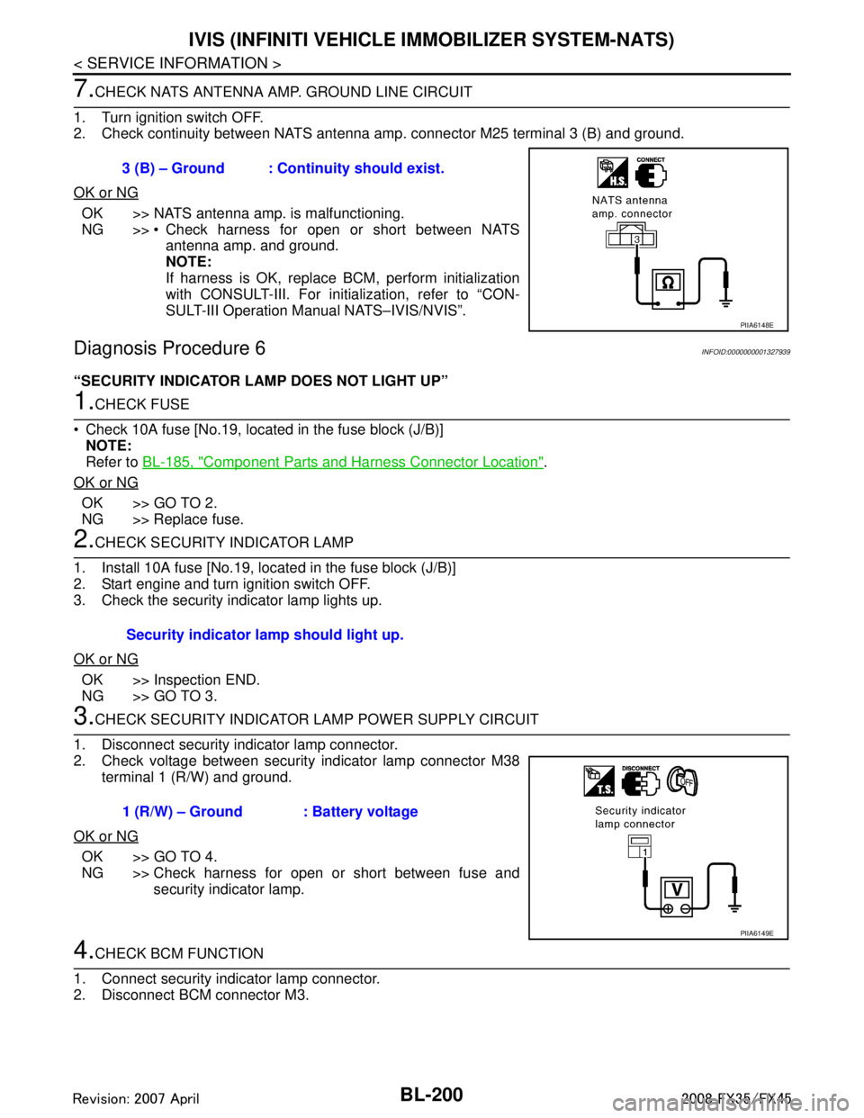
7.CHECK NATS ANTENNA AMP. GROUND LINE CIRCUIT
1. Turn ignition switch OFF.
2. Check continuity between NATS antenna am p. connector M25 terminal 3 (B) and ground.
OK or NG
OK >> NATS antenna amp. is malfunctioning.
NG >> Check harness for open or short between NATS antenna amp. and ground.
NOTE:
If harness is OK, replace BCM, perform initialization
with CONSULT-III. For initialization, refer to “CON-
SULT-III Operation Manual NATS–IVIS/NVIS”.
Diagnosis Procedure 6INFOID:0000000001327939
“SECURITY INDICATOR LAMP DOES NOT LIGHT UP”
1.CHECK FUSE
Check 10A fuse [No.19, located in the fuse block (J/B)] NOTE:
Refer to BL-185, "
Component Parts and Harness Connector Location".
OK or NG
OK >> GO TO 2.
NG >> Replace fuse.
2.CHECK SECURITY INDICATOR LAMP
1. Install 10A fuse [No.19, located in the fuse block (J/B)]
2. Start engine and turn ignition switch OFF.
3. Check the security indicator lamp lights up.
OK or NG
OK >> Inspection END.
NG >> GO TO 3.
3.CHECK SECURITY INDICATOR LA MP POWER SUPPLY CIRCUIT
1. Disconnect security indicator lamp connector.
2. Check voltage between security indicator lamp connector M38 terminal 1 (R/W) and ground.
OK or NG
OK >> GO TO 4.
NG >> Check harness for open or short between fuse and security indicator lamp.
4.CHECK BCM FUNCTION
1. Connect security indicator lamp connector.
2. Disconnect BCM connector M3. 3 (B) – Ground : Continuity should exist.
PIIA6148E
Security indicator lamp should light up.
1 (R/W) – Ground : Battery voltage
PIIA6149E
3AA93ABC3ACD3AC03ACA3AC03AC63AC53A913A773A893A873A873A8E3A773A983AC73AC93AC03AC3
3A893A873A873A8F3A773A9D3AAF3A8A3A8C3A863A9D3AAF3A8B3A8C
Page 935 of 3924

IVIS (INFINITI VEHICLE IMMOBILIZER SYSTEM-NATS)
BL-201
< SERVICE INFORMATION >
C
D E
F
G H
J
K L
M A
B
BL
N
O P
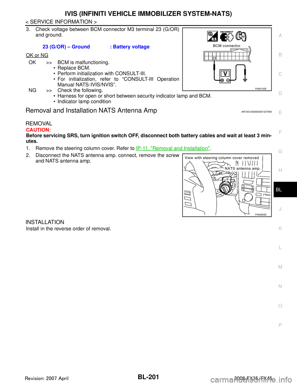
3. Check voltage between BCM connector M3 terminal 23 (G/OR) and ground.
OK or NG
OK >> BCM is malfunctioning. Replace BCM.
Perform initialization with CONSULT-III.
For initialization, refer to “CONSULT-III OperationManual NATS-IVIS/NVIS”.
NG >> Check the following. Harness for open or short between security indicator lamp and BCM.
Indicator lamp condition
Removal and Installa tion NATS Antenna AmpINFOID:0000000001327940
REMOVAL
CAUTION:
Before servicing SRS, turn ignition switch OFF, disconnect both battery cables and wait at least 3 min-
utes.
1. Remove the steering column cover. Refer to IP-11, "
Removal and Installation".
2. Disconnect the NATS antenna amp. connect, remove the screw and NATS antenna amp.
INSTALLATION
Install in the reverse order of removal. 23 (G/OR) – Ground : Battery voltage
PIIA6150E
PIIA6064E
3AA93ABC3ACD3AC03ACA3AC03AC63AC53A913A773A893A873A873A8E3A773A983AC73AC93AC03AC3
3A893A873A873A8F3A773A9D3AAF3A8A3A8C3A863A9D3AAF3A8B3A8C
Page 1000 of 3924

BR-16
< SERVICE INFORMATION >
VACUUM LINES
VACUUM LINES
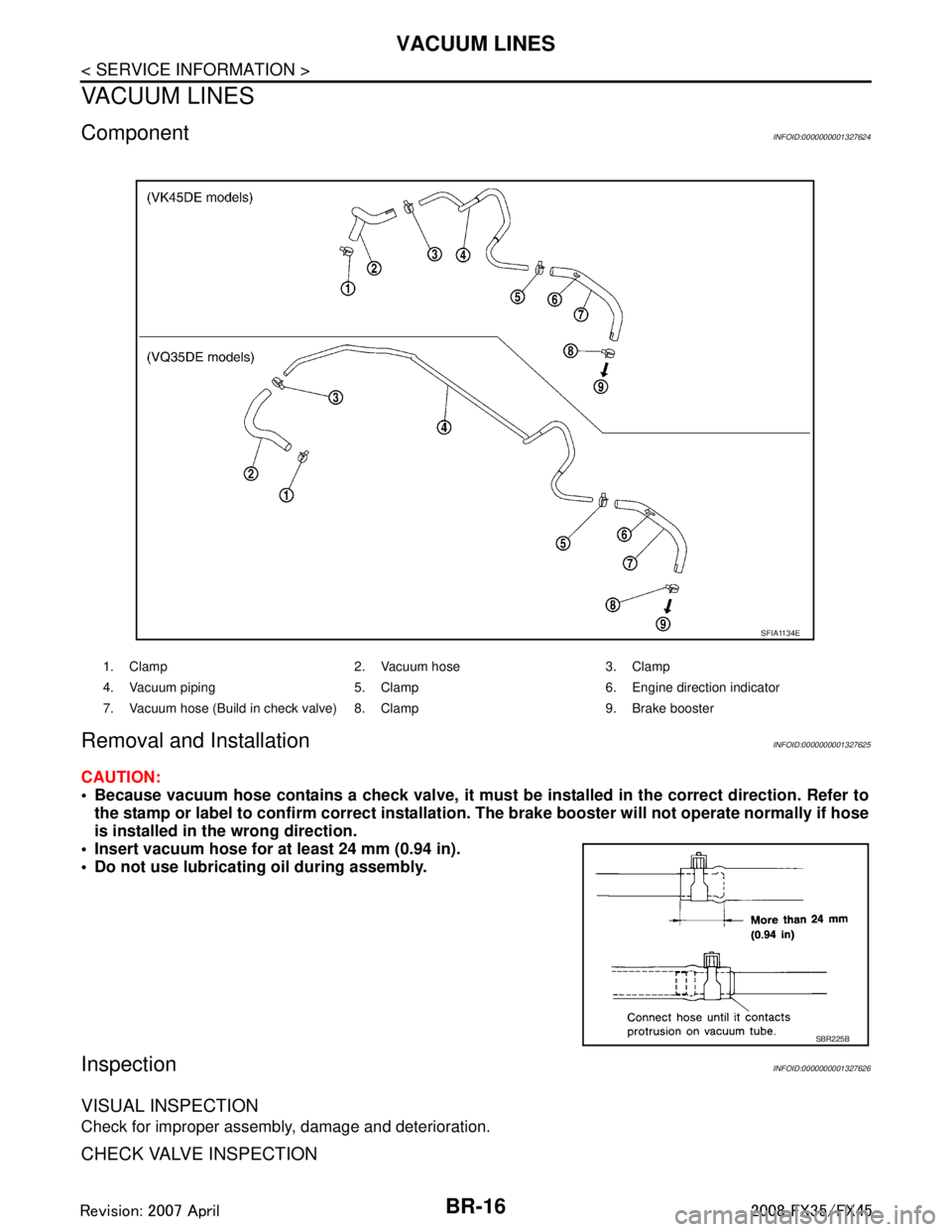
ComponentINFOID:0000000001327624
Removal and InstallationINFOID:0000000001327625
CAUTION:
Because vacuum hose contains a check valve, it must be installed in the correct direction. Refer to
the stamp or label to confirm co rrect installation. The brake booster will not ope rate normally if hose
is installed in the wrong direction.
Insert vacuum hose for at least 24 mm (0.94 in).
Do not use lubricating oil during assembly.
InspectionINFOID:0000000001327626
VISUAL INSPECTION
Check for improper assembly, damage and deterioration.
CHECK VALVE INSPECTION
1. Clamp 2. Vacuum hose 3. Clamp
4. Vacuum piping 5. Clamp 6. Engine direction indicator
7. Vacuum hose (Build in check valve) 8. Clamp 9. Brake booster
SFIA1134E
SBR225B
3AA93ABC3ACD3AC03ACA3AC03AC63AC53A913A773A893A873A873A8E3A773A983AC73AC93AC03AC3
3A893A873A873A8F3A773A9D3AAF3A8A3A8C3A863A9D3AAF3A8B3A8C
Page 1007 of 3924

FRONT DISC BRAKEBR-23
< SERVICE INFORMATION >
C
DE
G H
I
J
K L
M A
B
BR
N
O P
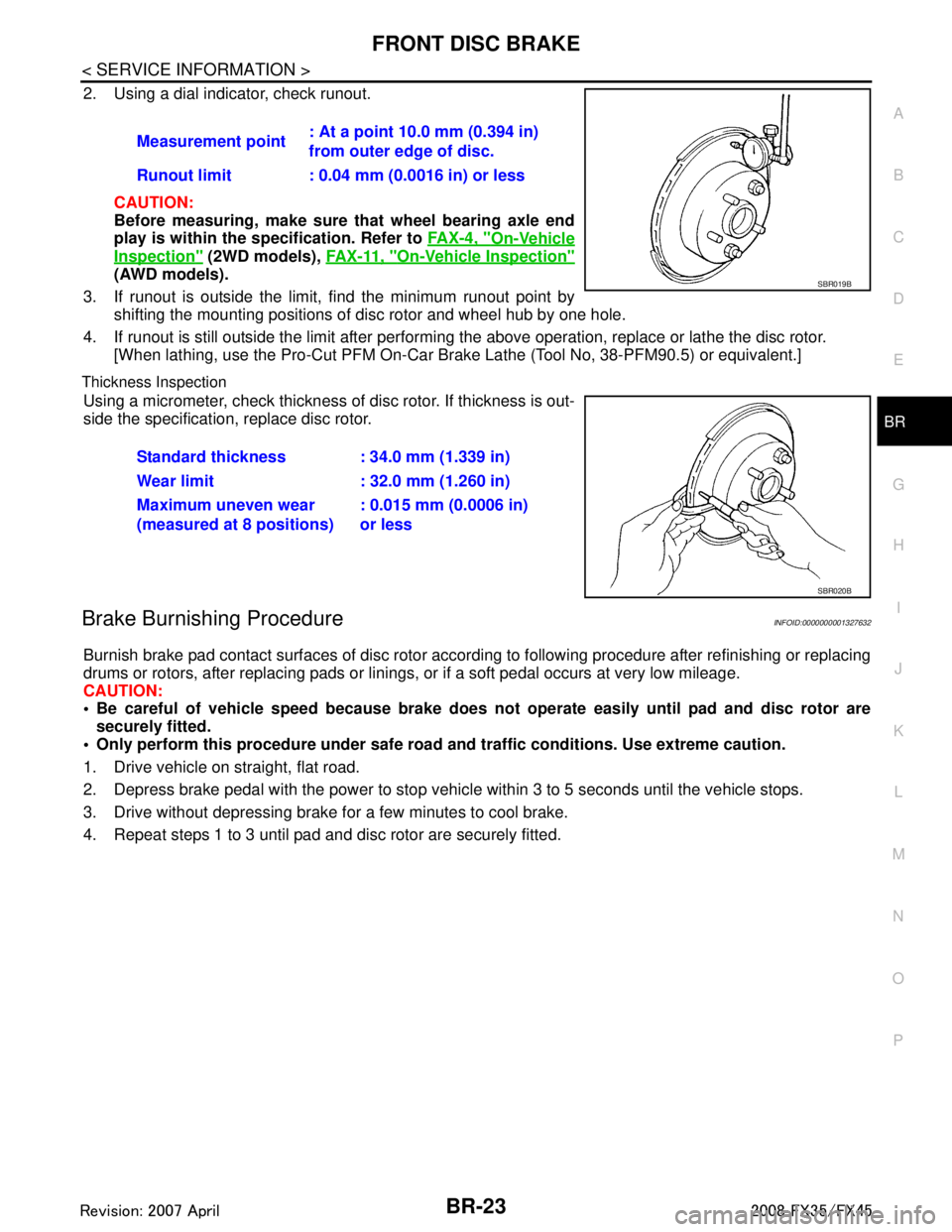
2. Using a dial indicator, check runout.
CAUTION:
Before measuring, make sure that wheel bearing axle end
play is within the sp ecification. Refer to FA X - 4 , "
On-Vehicle
Inspection" (2WD models), FA X - 11 , "On-Vehicle Inspection"
(AWD models).
3. If runout is outside the limit, find the minimum runout point by shifting the mounting positions of disc rotor and wheel hub by one hole.
4. If runout is still outside the limit after performing the above operation, replace or lathe the disc rotor.
[When lathing, use the Pro-Cut PFM On-Car Br ake Lathe (Tool No, 38-PFM90.5) or equivalent.]
Thickness Inspection
Using a micrometer, check thickness of disc rotor. If thickness is out-
side the specification, replace disc rotor.
Brake Burnishing ProcedureINFOID:0000000001327632
Burnish brake pad contact surfaces of disc rotor according to following procedure after refinishing or replacing
drums or rotors, after replacing pads or linings, or if a soft pedal occurs at very low mileage.
CAUTION:
Be careful of vehicle speed because brake does no t operate easily until pad and disc rotor are
securely fitted.
Only perform this procedure under safe road and traffic conditions. Use extreme caution.
1. Drive vehicle on straight, flat road.
2. Depress brake pedal with the power to stop vehicl e within 3 to 5 seconds until the vehicle stops.
3. Drive without depressing brake for a few minutes to cool brake.
4. Repeat steps 1 to 3 until pad and disc rotor are securely fitted. Measurement point
: At a point 10.0 mm (0.394 in)
from outer edge of disc.
Runout limit : 0.04 mm (0.0016 in) or less
SBR019B
Standard thickness : 34.0 mm (1.339 in)
Wear limit : 32.0 mm (1.260 in)
Maximum uneven wear
(measured at 8 positions) : 0.015 mm (0.0006 in)
or less
SBR020B
3AA93ABC3ACD3AC03ACA3AC03AC63AC53A913A773A893A873A873A8E3A773A983AC73AC93AC03AC3
3A893A873A873A8F3A773A9D3AAF3A8A3A8C3A863A9D3AAF3A8B3A8C
Page 1012 of 3924

BR-28
< SERVICE INFORMATION >
REAR DISC BRAKE
3. Apply brake fluid to piston, and press piston into cylinder bodyby hand to assemble piston side lip on piston boot properly into
groove on piston.
CAUTION:
Press piston evenly and change the pressing point to pre-
vent the inner wall of cylinder from being rubbed.
4. Fix piston boot with retaining ring. CAUTION:
Make sure boot is firmly in cylinder body groove.
Do not reuse retaining ring.
5. Install sliding pin bolts and sliding pin boots to torque member.
6. Apply PBC (Poly Butyl Cuprysil) grease or silicone- based grease to the backside of brake pad and to both
sides of shim, and attach inner shim and shim cover to inner pad, and the outer shim to outer pad.
7. Assembling shims and shim cover to pad. CAUTION:
When attaching pad retainer, inst all it firmly so that it does
not float up higher than torque member, as shown in the fig-
ure.
8. Install brake pad retainer and pad to torque member.
9. Install cylinder body. Tighten sliding pin bolts to the specified torque. Refer to BR-24, "
Component".
10. After installing caliper assembly, refill with new brake fluid and bleed air. Refer to BR-8, "
Bleeding Brake System".
DISC ROTOR INSPECTION
Visual Inspection
Check surfaces of disc rotor for uneven wear, cra cks, and serious damage. If a malfunction is detected,
replace applicable part.
Runout Inspection
1. Using wheel nuts, fix the disc rotor to wheels hub. (2 or more positions)
2. Using a dial indicator, check runout.
CAUTION:
Before measuring, make sure that wheel bearing axle end
play is within the specification. Refer to RAX-6, "
On-Vehicle
Inspection".
3. If runout is outside the limit, find minimum runout point by shift- ing mounting positions of disc rotor and wheel hub by one hole.
SFIA2279E
SFIA2280E
PFIA0273E
Measurement point : At a point 10 mm (0.394 in)
from outer edge of disc.
Runout limit : 0.05 mm (0.0020 in) or less
SBR019B
3AA93ABC3ACD3AC03ACA3AC03AC63AC53A913A773A893A873A873A8E3A773A983AC73AC93AC03AC3
3A893A873A873A8F3A773A9D3AAF3A8A3A8C3A863A9D3AAF3A8B3A8C
Page 1021 of 3924
![INFINITI FX35 2008 Workshop Manual
BRC-6
< SERVICE INFORMATION >[VDC/TCS/ABS]
PRECAUTIONS
If the following components are replaced with non-genui
ne components or converted, VDC OFF indicator
lamp and SLIP indicator lamp may turn on INFINITI FX35 2008 Workshop Manual
BRC-6
< SERVICE INFORMATION >[VDC/TCS/ABS]
PRECAUTIONS
If the following components are replaced with non-genui
ne components or converted, VDC OFF indicator
lamp and SLIP indicator lamp may turn on](/img/42/57017/w960_57017-1020.png)
BRC-6
< SERVICE INFORMATION >[VDC/TCS/ABS]
PRECAUTIONS
If the following components are replaced with non-genui
ne components or converted, VDC OFF indicator
lamp and SLIP indicator lamp may turn on or the VDC system may not operate properly. Components
related to suspension (shock absorber, strut, spring, bushing, etc.), Tires, wheels (exclude specified size),
components related to brake (pad, rotor, caliper, etc. ), components related to engine (muffler, ECM, etc.),
components related to body reinforcement (roll bar, tower bar, etc.).
Driving in the condition of breakage or excessive wear of suspension, tires or components related to the
brakes may cause VDC OFF indicator lamp and SLIP indicator lamp turn on, and the VDC system may not
operate properly.
When the TCS or VDC is activated by sudden accele ration or sudden turn, some noise may occur. The
noise is a result of the normal operation of the TCS and VDC.
When driving on roads which have extreme slopes (s uch as mountainous roads) or high banks (such as
sharp carves on a freeway), the VDC may not operate nor mally, or VDC OFF indicator lamp and SLIP indi-
cator lamp may turn on. However, this is not a malfunction, if normal operation can be resumed after restart-
ing engine.
Sudden turns (such as spin turns, acceleration turns) , drifting, etc. When VDC function is OFF (VDC OFF
SW ON) may cause the G sensor system indicate a malf unction. However, this is not a malfunction, if nor-
mal operation can be resumed after restarting engine.
Change 4 tires at a time. Be sure to use specified- size tires that have the same brand name and pattern.
Wheel sensor errors can be detected be self-diagnosis when tires have wide abrasion variations or the size
is different from the genuine tires.
3AA93ABC3ACD3AC03ACA3AC03AC63AC53A913A773A893A873A873A8E3A773A983AC73AC93AC03AC3
3A893A873A873A8F3A773A9D3AAF3A8A3A8C3A863A9D3AAF3A8B3A8C