fuel pump INFINITI FX35 2008 Service Manual
[x] Cancel search | Manufacturer: INFINITI, Model Year: 2008, Model line: FX35, Model: INFINITI FX35 2008Pages: 3924, PDF Size: 81.37 MB
Page 2866 of 3924

GI-4
< SERVICE INFORMATION >
PRECAUTIONS
To prevent serious burns:Avoid contact with hot metal parts.
Do not remove the radiator cap when the engine is hot.
Dispose of or recycle drained oil or the solvent used for cleaning parts in an appropriate manner.
Do not attempt to top off the fuel tank after the fuel pump nozzle
shuts off automatically.
Continued refueling may cause fuel overflow, resulting in fuel spray
and possibly a fire.
Clean all disassembled parts in the designated liquid or solvent prior to inspection or assembly.
Replace oil seals, gaskets, packings, O-rings, locking washers, cotter pins, self-locking nuts, etc. with new ones.
Replace inner and outer races of tapered roller bearings and needle bearings as a set.
Arrange the disassembled parts in accordance with their assembled locations and sequence.
Do not touch the terminals of electrical com ponents which use microcomputers (such as ECM).
Static electricity may damage internal electronic components.
After disconnecting vacuum or air hoses, atta ch a tag to indicate the proper connection.
Use only the fluids and lubricants specified in this manual.
Use approved bonding agent, sealants or their equivalents when required.
Use hand tools, power tools (disassembly only) and recommended special tools where specified for safe and efficient service repairs.
When repairing the fuel, oil, water, vacuum or exhaust systems,
check all affected lines for leaks.
Before servicing the vehicle: Protect fenders, upholstery and carpeting with appropriate covers.
Take caution that keys, buckles or buttons do not scratch paint.
WARNING:
To prevent ECM from storing the diagnostic tro uble codes, do not carelessly disconnect the harness
connectors which are related to the engine cont rol system and TCM (transmission control module)
system. The connectors should be disconnected on ly when working according to the WORK FLOW of
TROUBLE DIAGNOSES in EC and AT sections.
Precaution for Three Way CatalystINFOID:0000000001325655
If a large amount of unburned fuel flows into the catalyst , the catalyst temperature will be excessively high. To
prevent this, follow the instructions.
Use unleaded gasoline only. Leaded gasoline will seriously damage the three way catalyst.
When checking for ignition spark or measuring engine compression, make tests quickly and only when nec- essary.
Do not run engine when the fuel tank level is low, otherwise the engine may misfire, causing damage to the
catalyst.
SGI233
PBIC0190E
SGI234
3AA93ABC3ACD3AC03ACA3AC03AC63AC53A913A773A893A873A873A8E3A773A983AC73AC93AC03AC3
3A893A873A873A8F3A773A9D3AAF3A8A3A8C3A863A9D3AAF3A8B3A8C
Page 2867 of 3924

PRECAUTIONSGI-5
< SERVICE INFORMATION >
C
DE
F
G H
I
J
K L
M B
GI
N
O P
Do not place the vehicle on flammable material. Keep flammable material off the exhaust pipe and the three
way catalyst.
Precaution for Fuel (Unlead ed Premium Gasoline Recommended)INFOID:0000000001325656
VQ35DE
INFINITI recommends the use of unleaded premium gasoli ne with an octane rating of at least 91 AKI (Anti-
Knock Index) number (Research octane number 96).
If unleaded premium gasoline is not available, you may use unleaded regular gasoline with an octane rating of
at least 87AKI number (Research octane number 91), but you may notice a decrease in performance.
CAUTION:
Do not use leaded gasoli ne. Using leaded gasoline will damage the three way catalyst. Do not use E-85
fuel (85% fuel ethanol, 15% unlead ed gasoline) unless the vehicle is specifically designed for E-85 fuel
(i.e. Flexible Fuel Vehicle - FFV models). Using a fu el other than that specified could adversely affect
the emission control devices and systems, and could also affect the warranty coverage validity.
Precaution for Fuel (Unleaded Premium Gasoline Required)INFOID:0000000001325657
VK45DE
Use unleaded premium gasoline with an octane rating of at least 91 AKI (Anti-Knock Index) number (Research
octane number 96).
If unleaded premium gasoline is not available, unleaded r egular gasoline with an octane rating of at least 87
AKI number (Research octane number 91) can be us ed, but only under the following precautions:
have the fuel tank filled only partially with unl eaded regular gasoline, and fill up with unleaded premium gas-
oline as soon as possible.
avoid full throttle driving and abrupt acceleration.
However, for maximum vehicle performance, the u se of unleaded premium gasoline is recommended.
CAUTION:
Do not use leaded gasoli ne. Using leaded gasoline will damage the three way catalyst. Do not use E-85
fuel (85% fuel ethanol, 15% unlead ed gasoline) unless the vehicle is specifically designed for E-85 fuel
(i.e. Flexible Fuel Vehicle - FFV models). Using a fu el other than that specified could adversely affect
the emission control devices and systems, and could also affect the warranty coverage validity.
Precaution for Multiport Fuel Inject ion System or Engine Control SystemINFOID:0000000001325658
Before connecting or disconnecti ng any harness connector for the
multiport fuel injection system or ECM:
Turn ignition switch to “OFF” position.
Disconnect negative battery terminal.
Otherwise, there may be damage to ECM.
Before disconnecting pressurized fuel line from fuel pump to injec- tors, be sure to release fuel pressure.
Be careful not to jar components such as ECM and mass air flow sensor.
Precaution for HosesINFOID:0000000001325659
HOSE REMOVAL AND INSTALLATION
SGI787
3AA93ABC3ACD3AC03ACA3AC03AC63AC53A913A773A893A873A873A8E3A773A983AC73AC93AC03AC3
3A893A873A873A8F3A773A9D3AAF3A8A3A8C3A863A9D3AAF3A8B3A8C
Page 2912 of 3924

GI-50
< SERVICE INFORMATION >
TERMINOLOGY
Nonvolatile random access memory NVRAM ***
On board diagnostic system OBD system Self-diagnosis
Open loop OL Open loop
Oxidation catalyst OC Catalyst
Oxidation catalytic converter system OC system ***
Oxygen sensor O2S Exhaust gas sensor
Park position switch *** Park switch
Park/neutral position switch PNP switchPark/neutral switch
Inhibitor switch
Neutral position switch
Periodic trap oxidizer system PTOX system ***
Positive crankcase ventilation PCV Positive crankcase ventilation
Positive crankcase ventilation valve PCV valve PCV valve
Powertrain cont rol module PCM ***
Programmable read only memory PROM ***
Pulsed secondary air injection control sole-
noid valve PAIRC solenoid valve AIV control solenoid valve
Pulsed secondary air injection system PAIR system Air induction valve (AIV) control
Pulsed secondary air injection valve PAIR valve Air induction valve
Random access memory RAM ***
Read only memory ROM ***
Scan tool ST ***
Secondary air injection pump AIR pump ***
Secondary air injection system AIR system ***
Sequential multiport fuel injection system SFI system Sequential fuel injection
Service reminder indicator SRI ***
Simultaneous multiport fuel injection sys-
tem *** Simultaneous fuel injection
Smoke puff limiter system SPL system ***
Supercharger SC ***
Supercharger bypass SCB ***
System readiness test SRT ***
Thermal vacuum valve TVV Thermal vacuum valve
Three way catalyst TWC Catalyst
Three way catalytic converter system TWC system ***
Three way + oxidation catalyst TWC + OC Catalyst
Three way + oxidation catalytic converter
system TWC + OC system ***
Throttle body TB Throttle chamber
SPI body
Throttle body fuel injection system TBI system Fuel injection control
Throttle position TP Throttle position
Throttle position sensor TPS Throttle sensor
Throttle position switch TP switch Throttle switch
Torque converter clutch solenoid valve TCC solenoid valve Lock-up cancel solenoid
Lock-up solenoid
NEW TERM
NEW ACRONYM /
ABBREVIATION OLD TERM
3AA93ABC3ACD3AC03ACA3AC03AC63AC53A913A773A893A873A873A8E3A773A983AC73AC93AC03AC3
3A893A873A873A8F3A773A9D3AAF3A8A3A8C3A863A9D3AAF3A8B3A8C
Page 3425 of 3924

HARNESSPG-61
< SERVICE INFORMATION >
C
DE
F
G H
I
J
L
M A
B
PG
N
O P
Code Section Wiring Diagram Name
A/C ATC Air Conditioner
AF1B1 EC Air Fuel Ratio Sensor 1 Bank 1
AF1B2 EC Air Fuel Ratio Sensor 1 Bank 2
AF1HB1 EC Air Fuel Ratio Sensor 1 Heater Bank 1
AF1HB2 EC Air Fuel Ratio Sensor 1 Heater Bank 2
APPS1 EC Accelerator Pedal Position Sensor
APPS2 EC Accelerator Pedal Position Sensor
APPS3 EC Accelerator Pedal Position Sensor
ASC/BS EC Automatic Speed Control Device (ASCD) Brake Switch
ASC/SW EC Automatic Speed Control Device (ASCD) Steering Switch
ASCBOF EC Automatic Speed Control Device (ASCD) Brake Switch
ASCIND EC Automatic Speed Contro l Device (ASCD) Indicator
AT/IND DI A/T Indicator Lamp
AUDIO AV Audio
AUT/DP SE Automatic Drive Positioner
AUTO/L LT Automatic Light System
AWD TF AWD Control System
B/CLOS BL Back Door Closure System
BACK/L LT Back-Up Lamp
BRK/SW EC Brake Switch
CAN AT CAN Communication Line
CAN EC CAN Communication Line
CAN LAN CAN System
CHARGE SC Charging System
CHIME DI Warning Chime
CLOCK DI Clock
COMBSW LT Combination Switch
COMM AV Audio Visual Communication Line
COMPAS DI Compass
COOL/F EC Cooling Fan Control
D/LOCK BL Power Door Lock
DEF GW Rear Window Defogger
DTRL LT Headlamp - With Daytime Light System
ECM/PW EC ECM Power Supply for Back-Up
ECTS EC Engine Coolant Temperature Sensor
ETC1 EC Electric Throttle Control Function
ETC2 EC Electric Throttle Control Motor Relay
ETC3 EC Electric Throttle Control Motor
F/FOG LT Front Fog Lamp
F/PUMP EC Fuel Pump
FTS AT A/T Fluid Temperature Sensor Circuit
FTTS EC Fuel Tank Temperature Sensor
FUELB1 EC Fuel Injection System Function (Bank 1)
FUELB2 EC Fuel Injection System Function (Bank 2)
3AA93ABC3ACD3AC03ACA3AC03AC63AC53A913A773A893A873A873A8E3A773A983AC73AC93AC03AC3
3A893A873A873A8F3A773A9D3AAF3A8A3A8C3A863A9D3AAF3A8B3A8C
Page 3621 of 3924
SC-12
< SERVICE INFORMATION >
STARTING SYSTEM
1. Remove fuel pump fuse.
2. Crank or start the engine (where possible) until the fuel pressure is released.
1.CHECK “B” TERMINAL CIRCUIT
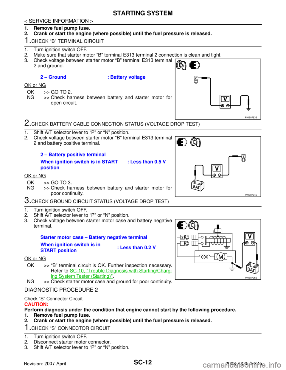
1. Turn ignition switch OFF.
2. Make sure that starter motor “B” terminal E313 terminal 2 connection is clean and tight.
3. Check voltage between starter motor “B” terminal E313 terminal 2 and ground.
OK or NG
OK >> GO TO 2.
NG >> Check harness between battery and starter motor for open circuit.
2.CHECK BATTERY CABLE CONNECTION STATUS (VOLTAGE DROP TEST)
1. Shift A/T selector lever to “P” or “N” position.
2. Check voltage between starter motor “B” terminal E313 terminal 2 and battery positive terminal.
OK or NG
OK >> GO TO 3.
NG >> Check harness between battery and starter motor for poor continuity.
3.CHECK GROUND CIRCUIT STATUS (VOLTAGE DROP TEST)
1. Turn ignition switch OFF.
2. Shift A/T selector lever to “P” or “N” position.
3. Check voltage between starter motor case and battery negative terminal.
OK or NG
OK >> “B” terminal circuit is OK. Further inspection necessary. Refer to SC-10, "
Trouble Diagnosis with Starting/Charg-
ing System Tester (Starting)".
NG >> Check starter motor case and ground for poor continuity.
DIAGNOSTIC PROCEDURE 2
Check “S” Connector Circuit
CAUTION:
Perform diagnosis under the condi tion that engine cannot start by the following procedure.
1. Remove fuel pump fuse.
2. Crank or start the engine (where possi ble) until the fuel pressure is released.
1.CHECK “S” CONNECTOR CIRCUIT
1. Turn ignition switch OFF.
2. Disconnect starter motor connector.
3. Shift A/T selector lever to “P” or “N” position. 2 – Ground : Battery voltage
PKIB8793E
2 – Battery positive terminal
When ignition switch is in START
position
: Less than 0.5 V
PKIB8794E
Starter motor case – Battery negative terminal
When ignition switch is in
START position
: Less than 0.2 V
PKIB8795E
3AA93ABC3ACD3AC03ACA3AC03AC63AC53A913A773A893A873A873A8E3A773A983AC73AC93AC03AC3
3A893A873A873A8F3A773A9D3AAF3A8A3A8C3A863A9D3AAF3A8B3A8C