engine INFINITI FX35 2008 Owner's Manual
[x] Cancel search | Manufacturer: INFINITI, Model Year: 2008, Model line: FX35, Model: INFINITI FX35 2008Pages: 3924, PDF Size: 81.37 MB
Page 80 of 3924
PRECAUTIONSAT-7
< SERVICE INFORMATION >
DE
F
G H
I
J
K L
M A
B
AT
N
O P
PRECAUTIONS
Precaution for Supplemental Restraint System (SRS) "AIR BAG" and "SEAT BELT
PRE-TENSIONER"
INFOID:0000000001612925
The Supplemental Restraint System such as “A IR BAG” and “SEAT BELT PRE-TENSIONER”, used along
with a front seat belt, helps to reduce the risk or severi ty of injury to the driver and front passenger for certain
types of collision. This system includes seat belt switch inputs and dual stage front air bag modules. The SRS
system uses the seat belt switches to determine the front air bag deployment, and may only deploy one front
air bag, depending on the severity of a collision and whether the front occupants are belted or unbelted.
Information necessary to service the system safely is included in the “SUPPLEMENTAL RESTRAINT SYS-
TEM” and “SEAT BELTS” of this Service Manual.
WARNING:
To avoid rendering the SRS inoper ative, which could increase the risk of personal injury or death in
the event of a collision which would result in air bag inflation, all maintenance must be performed by
an authorized NISSAN/INFINITI dealer.
Improper maintenance, including in correct removal and installation of the SRS, can lead to personal
injury caused by unintentional act ivation of the system. For removal of Spiral Cable and Air Bag
Module, see the “SUPPLEMEN TAL RESTRAINT SYSTEM”.
Do not use electrical test equipm ent on any circuit related to the SRS unless instructed to in this
Service Manual. SRS wiring harnesses can be identi fied by yellow and/or orange harnesses or har-
ness connectors.
Precaution for On Board Diagnosis (OBD) System of A/T and EngineINFOID:0000000001327123
The ECM has an on board diagnostic system. It will light up the malfunction indicator lamp (MIL) to warn the
driver of a malfunction causing emission deterioration.
CAUTION:
Be sure to turn the ignition sw itch OFF and disconnect the battery cable from the negative terminal
before any repair or inspection work. The open/s hort circuit of related switches, sensors, solenoid
valves, etc. Will cause the MIL to light up.
Be sure to connect and lock the connectors secure ly after work. A loose (unlocked) connector will
cause the MIL to light up due to an open circuit. (Be sure the connector is free from water, grease,
dirt, bent terminals, etc.)
Be sure to route and secure the harnesses properly after work. Interference of the harness with a
bracket, etc. May cause the MIL to li ght up due to a short circuit.
Be sure to connect rubber tubes properly afte r work. A misconnected or disconnected rubber tube
may cause the MIL to light up due to a malfunction of the EVAP system or fuel injection system, etc.
Be sure to erase the unnecessary malfunction informa tion (repairs completed) from the TCM and
ECM before returning the vehicle to the customer.
PrecautionINFOID:0000000001327124
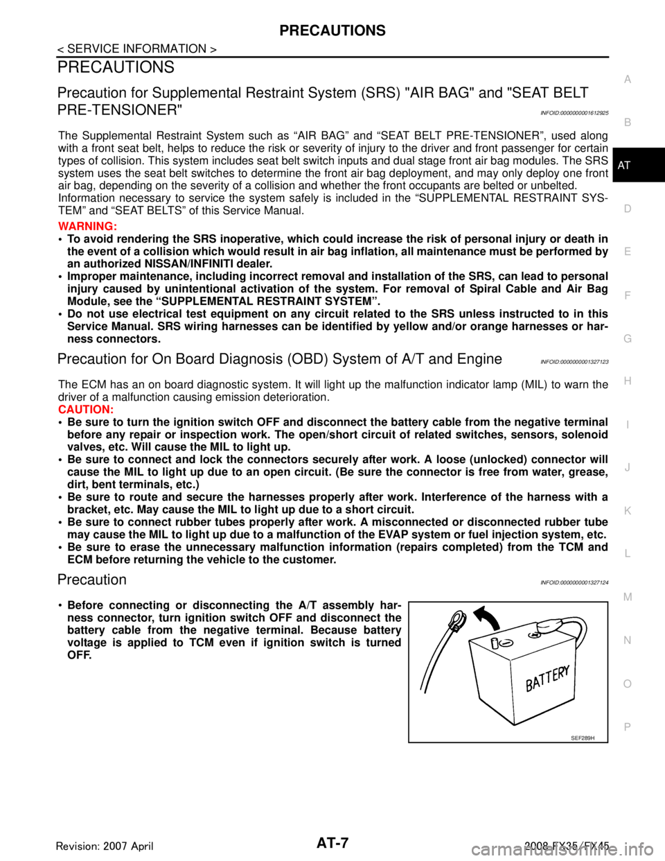
Before connecting or disco nnecting the A/T assembly har-
ness connector, turn ignition switch OFF and disconnect the
battery cable from the negative terminal. Because battery
voltage is applied to TCM even if ignition switch is turned
OFF.
SEF289H
3AA93ABC3ACD3AC03ACA3AC03AC63AC53A913A773A893A873A873A8E3A773A983AC73AC93AC03AC3
3A893A873A873A8F3A773A9D3AAF3A8A3A8C3A863A9D3AAF3A8B3A8C
Page 84 of 3924
A/T FLUIDAT-11
< SERVICE INFORMATION >
DE
F
G H
I
J
K L
M A
B
AT
N
O P
A/T FLUID
Changing A/T FluidINFOID:0000000001327128
1. Warm up ATF.
2. Stop engine.
3. Loosen the level gauge bolt.
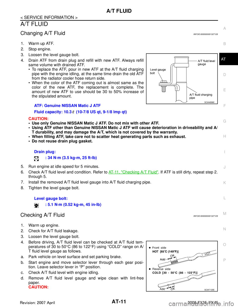
4. Drain ATF from drain plug and refill with new ATF. Always refill same volume with drained ATF.
To replace the ATF, pour in new ATF at the A/T fluid chargingpipe with the engine idling, at the same time drain the old ATF
from the radiator cooler hose return side.
When the color of the ATF coming out is almost same as the
color of the new ATF, the replacement is complete. The
amount of new ATF to use should be 30 to 50% increase of
the stipulated amount.
CAUTION:
Use only Genuine NISSAN Matic J ATF. Do not mix with other ATF.
Using ATF other than Genuine NISSAN Matic J AT F will cause deterioration in driveability and A/
T durability, and may damage the A/T, which is not covered by the warranty.
When filling ATF, take care not to scatter heat generating parts such as exhaust.
Do not reuse drain plug gasket.
5. Run engine at idle speed for 5 minutes.
6. Check A/T fluid level and condition. Refer to AT- 11 , "
Checking A/T Fluid". If ATF is still dirty, repeat step 2.
through 5.
7. Install the removed A/T fluid level gauge into A/T fluid charging pipe.
8. Tighten the level gauge bolt.
Checking A/T FluidINFOID:0000000001327129
1. Warm up engine.
2. Check for A/T fluid leakage.
3. Loosen the level gauge bolt.
4. Before driving, A/T fluid level can be checked at A/T fluid tem- peratures of 30 to 50 °C (86 to 122 °F) using “COLD” range on A/
T fluid level gauge as follows.
a. Park vehicle on level surface and set parking brake.
b. Start engine and move selector lever through each gear posi- tion. Leave selector lever in “P” position.
c. Check A/T fluid level with engine idling.
d. Remove A/T fluid level gauge and wipe clean with lint-free paper.
CAUTION:ATF: Genuine NISSAN Matic J ATF
Fluid capacity: 10.3 (10-7/8 US qt, 9-1/8 lmp qt)
Drain plug:
: 34 N·m (3.5 kg-m, 25 ft-lb)
Level gauge bolt: : 5.1 N·m (0.52 kg-m, 45 in-lb)
SCIA4896E
SCIA7120E
3AA93ABC3ACD3AC03ACA3AC03AC63AC53A913A773A893A873A873A8E3A773A983AC73AC93AC03AC3
3A893A873A873A8F3A773A9D3AAF3A8A3A8C3A863A9D3AAF3A8B3A8C
Page 94 of 3924
A/T CONTROL SYSTEMAT-21
< SERVICE INFORMATION >
DE
F
G H
I
J
K L
M A
B
AT
N
O P
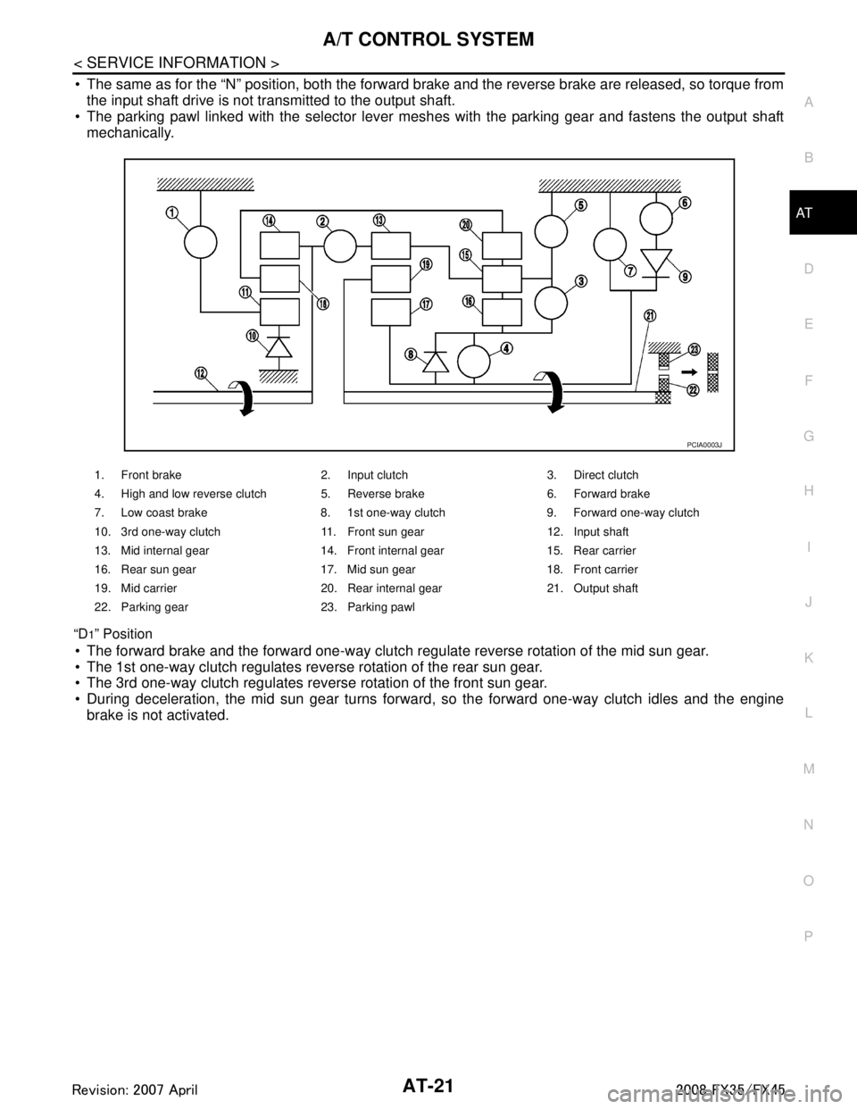
The same as for the “N” position, both the forward brake and the reverse brake are released, so torque from the input shaft drive is not transmitted to the output shaft.
The parking pawl linked with the selector lever mes hes with the parking gear and fastens the output shaft
mechanically.
“D1” Position
The forward brake and the forward one-way clutch regulate reverse rotation of the mid sun gear.
The 1st one-way clutch regulates reverse rotation of the rear sun gear.
The 3rd one-way clutch regulates reverse rotation of the front sun gear.
During deceleration, the mid sun gear turns forwar d, so the forward one-way clutch idles and the engine
brake is not activated.
1. Front brake 2. Input clutch 3. Direct clutch
4. High and low reverse clutch 5. Reverse brake 6. Forward brake
7. Low coast brake 8. 1st one-way clutch 9. Forward one-way clutch
10. 3rd one-way clutch 11. Front sun gear 12. Input shaft
13. Mid internal gear 14. Front internal gear 15. Rear carrier
16. Rear sun gear 17. Mid sun gear 18. Front carrier
19. Mid carrier 20. Rear internal gear 21. Output shaft
22. Parking gear 23. Parking pawl
PCIA0003J
3AA93ABC3ACD3AC03ACA3AC03AC63AC53A913A773A893A873A873A8E3A773A983AC73AC93AC03AC3
3A893A873A873A8F3A773A9D3AAF3A8A3A8C3A863A9D3AAF3A8B3A8C
Page 95 of 3924
AT-22
< SERVICE INFORMATION >
A/T CONTROL SYSTEM
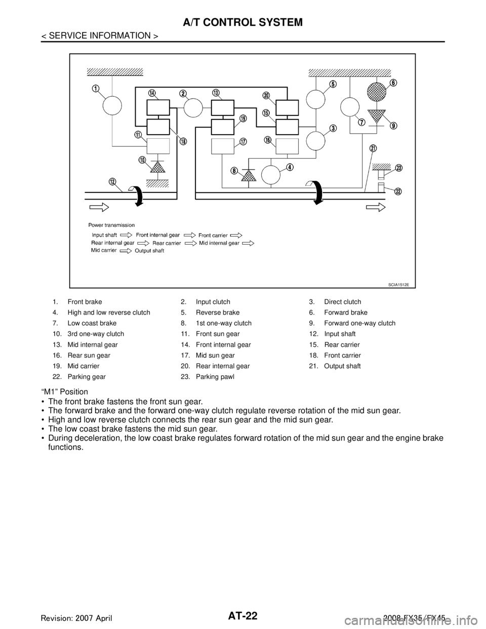
“M1” Position
The front brake fastens the front sun gear.
The forward brake and the forward one-way clutch regulate reverse rotation of the mid sun gear.
High and low reverse clutch connects the rear sun gear and the mid sun gear.
The low coast brake fastens the mid sun gear.
During deceleration, the low coast brake regulates forward rotation of the mid sun gear and the engine brake
functions.
1. Front brake 2. Input clutch 3. Direct clutch
4. High and low reverse clutch 5. Reverse brake 6. Forward brake
7. Low coast brake 8. 1st one-way clutch 9. Forward one-way clutch
10. 3rd one-way clutch 11. Front sun gear 12. Input shaft
13. Mid internal gear 14. Front internal gear 15. Rear carrier
16. Rear sun gear 17. Mid sun gear 18. Front carrier
19. Mid carrier 20. Rear internal gear 21. Output shaft
22. Parking gear 23. Parking pawl
SCIA1512E
3AA93ABC3ACD3AC03ACA3AC03AC63AC53A913A773A893A873A873A8E3A773A983AC73AC93AC03AC3
3A893A873A873A8F3A773A9D3AAF3A8A3A8C3A863A9D3AAF3A8B3A8C
Page 96 of 3924

A/T CONTROL SYSTEMAT-23
< SERVICE INFORMATION >
DE
F
G H
I
J
K L
M A
B
AT
N
O P
“D
2” Position
The forward brake and the forward one-way clutch
regulate reverse rotation of the mid sun gear.
The 3rd one-way clutch regulates reverse rotation of the front sun gear.
The direct clutch is coupled, and the rear carrier and rear sun gear are connected.
During deceleration, the mid sun gear turns forward, so the forward one-way clutch idles and engine brake is
not activated.
1. Front brake 2. Input clutch 3. Direct clutch
4. High and low reverse clutch 5. Reverse brake 6. Forward brake
7. Low coast brake 8. 1st one-way clutch 9. Forward one-way clutch
10. 3rd one-way clutch 11. Front sun gear 12. Input shaft
13. Mid internal gear 14. Front internal gear 15. Rear carrier
16. Rear sun gear 17. Mid sun gear 18. Front carrier
19. Mid carrier 20. Rear internal gear 21. Output shaft
22. Parking gear 23. Parking pawl
SCIA1513E
3AA93ABC3ACD3AC03ACA3AC03AC63AC53A913A773A893A873A873A8E3A773A983AC73AC93AC03AC3
3A893A873A873A8F3A773A9D3AAF3A8A3A8C3A863A9D3AAF3A8B3A8C
Page 97 of 3924

AT-24
< SERVICE INFORMATION >
A/T CONTROL SYSTEM
“M2” Position
The front brake fastens the front sun gear.
The forward brake and the forward one-way clutch regulate reverse rotation of the mid sun gear.
The direct clutch is coupled, and the rear carrier and rear sun gear are connected.
The low coast brake fastens the mid sun gear.
During deceleration, the low coast brake regulates forward rotation of the mid sun gear and the engine brake
functions.
1. Front brake 2. Input clutch 3. Direct clutch
4. High and low reverse clutch 5. Reverse brake 6. Forward brake
7. Low coast brake 8. 1st one-way clutch 9. Forward one-way clutch
10. 3rd one-way clutch 11. Front sun gear 12. Input shaft
13. Mid internal gear 14. Front internal gear 15. Rear carrier
16. Rear sun gear 17. Mid sun gear 18. Front carrier
19. Mid carrier 20. Rear internal gear 21. Output shaft
22. Parking gear 23. Parking pawl
SCIA1514E
3AA93ABC3ACD3AC03ACA3AC03AC63AC53A913A773A893A873A873A8E3A773A983AC73AC93AC03AC3
3A893A873A873A8F3A773A9D3AAF3A8A3A8C3A863A9D3AAF3A8B3A8C
Page 102 of 3924

A/T CONTROL SYSTEMAT-29
< SERVICE INFORMATION >
DE
F
G H
I
J
K L
M A
B
AT
N
O P
TCM FunctionINFOID:0000000001327135
The function of the TCM is to:
Receive input signals sent from various switches and sensors.
Determine required line pressure, shifting point, lock-up operation, and engine brake operation.
Send required output signals to the respective solenoids.
CONTROL SYSTEM OUTLINE
The automatic transmission senses vehicle operating condi tions through various sensors or signals. It always
controls the optimum shift position and reduces shifting and lock-up shocks.
1. Front brake 2. Input clutch 3. Direct clutch
4. High and low reverse clutch 5. Reverse brake 6. Forward brake
7. Low coast brake 8. 1st one-way clutch 9. Forward one-way clutch
10. 3rd one-way clutch 11. Front sun gear 12. Input shaft
13. Mid internal gear 14. Front internal gear 15. Rear carrier
16. Rear sun gear 17. Mid sun gear 18. Front carrier
19. Mid carrier 20. Rear internal gear 21. Output shaft
22. Parking gear 23. Parking pawl
SCIA1519E
SENSORS (or SIGNALS)
⇒TCM
⇒ACTUATORS
PNP switch
Accelerator pedal position signal
Closed throttle position signal
Wide open throttle position signal
Engine speed signal
A/T fluid temperature sensor
Revolution sensor
Vehicle speed signal
Manual mode switch signal
Stop lamp switch signal
Turbine revolution sensor
ATF pressure switch Shift control
Line pressure control
Lock-up control
Engine brake control
Timing control
Fail-safe control
Self-diagnosis
CONSULT-III co
mmunication
line
Duet-EA control
CAN system Input clutch solenoid valve
Direct clutch solenoid valve
Front brake solenoid valve
High and low reverse clutch sole-
noid valve
Low coast brake solenoid valve
Torque converter clutch solenoid
valve
Line pressure solenoid valve
A/T CHECK indicator lamp
Starter relay
Back-up lamp relay
:
Page 104 of 3924

A/T CONTROL SYSTEMAT-31
< SERVICE INFORMATION >
DE
F
G H
I
J
K L
M A
B
AT
N
O P
Input/Output Signal of TCMINFOID:0000000001327137
*1: Spare for vehicle speed sensor·A/T (revolution sensor)
*2: Spare for accelerator pedal position signal
*3: If these input and output signals are different, the TCM triggers the fail-safe function.
*4: Used as a condition for starting self-diagnostics; if self-diagnostics are not started, it is judged that there is some kin d of error.
*5: Input by CAN communications
*6: Output by CAN communications
Line Pressure ControlINFOID:0000000001327138
When an input torque signal equivalent to the engine drive force is sent from the ECM to the TCM, the TCM
controls the line pressure solenoid.
Control item Line
pressure control Vehicle
speed
control Shift
control Lock-up
control Engine
brake
control Fail-safe
function (*3) Self-diag-
nostics
function
Input Accelerator pedal position signal
(*5)XXXXXXX
Vehicle speed sensor A/T
(revolution sensor) XXXXXXX
Vehicle speed sensor MTR
(*1) (*5)X
Closed throttle position signal
(*5)X (*2) X X X X (*4)
Wide open throttle position signal
(*5)XX (*4)
Turbine revolution sensor 1 X X X X X
Turbine revolution sensor 2
(for 4th speed only) XXXXX
Engine speed signals
(*5)XXXXXXX
Stop lamp switch signal
(*5)XXX X (*4)
A/T fluid temperature sensors 1, 2 X X X X X X
ASCD or
ICC Operation signal
(*5)XXX
Overdrive cancel sig-
nal
(*5)X
Out-
put Direct clutch solenoid X X X X
Input clutch solenoid X X X X
High and low reverse clutch sole-
noid
XX XX
Front brake solenoid X X X X
Low coast brake solenoid (ATF
pressure switch 2) XX XXX
Line pressure solenoid X X X X X X X
TCC solenoid X X X
Self-diagnostics table
(*6)X
Starter relay XX
3AA93ABC3ACD3AC03ACA3AC03AC63AC53A913A773A893A873A873A8E3A773A983AC73AC93AC03AC3
3A893A873A873A8F3A773A9D3AAF3A8A3A8C3A863A9D3AAF3A8B3A8C
Page 105 of 3924
AT-32
< SERVICE INFORMATION >
A/T CONTROL SYSTEM
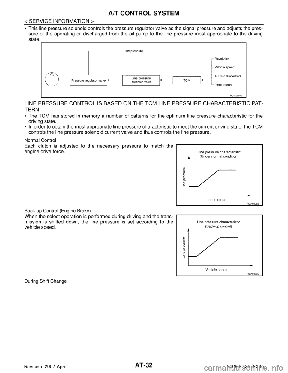
This line pressure solenoid controls the pressure regulator valve as the signal pressure and adjusts the pres-
sure of the operating oil discharged from the oil pump to the line pressure most appropriate to the driving
state.
LINE PRESSURE CONTROL IS BASED ON TH E TCM LINE PRESSURE CHARACTERISTIC PAT-
TERN
The TCM has stored in memory a number of patterns fo r the optimum line pressure characteristic for the
driving state.
In order to obtain the most appropriate line pressure char acteristic to meet the current driving state, the TCM
controls the line pressure solenoid current valve and thus controls the line pressure.
Normal Control
Each clutch is adjusted to the necessary pressure to match the
engine drive force.
Back-up Control (Engine Brake)
When the select operation is performed during driving and the trans-
mission is shifted down, the line pressure is set according to the
vehicle speed.
During Shift Change
PCIA0007E
PCIA0008E
PCIA0009E
3AA93ABC3ACD3AC03ACA3AC03AC63AC53A913A773A893A873A873A8E3A773A983AC73AC93AC03AC3
3A893A873A873A8F3A773A9D3AAF3A8A3A8C3A863A9D3AAF3A8B3A8C
Page 106 of 3924
A/T CONTROL SYSTEMAT-33
< SERVICE INFORMATION >
DE
F
G H
I
J
K L
M A
B
AT
N
O P
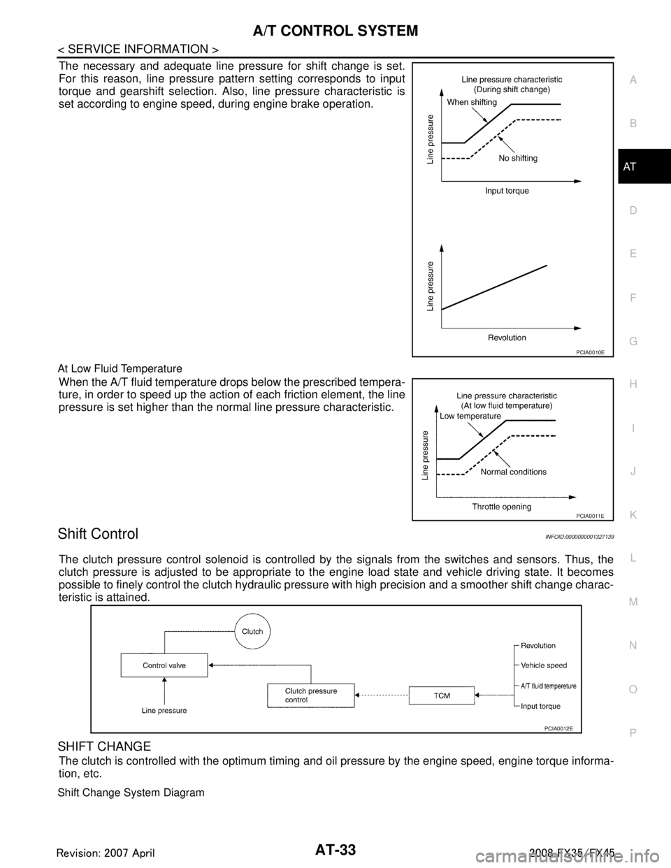
The necessary and adequate line pressure for shift change is set.
For this reason, line pressure pattern setting corresponds to input
torque and gearshift selection. Also, line pressure characteristic is
set according to engine speed, during engine brake operation.
At Low Fluid Temperature
When the A/T fluid temperature drops below the prescribed tempera-
ture, in order to speed up the action of each friction element, the line
pressure is set higher than the normal line pressure characteristic.
Shift ControlINFOID:0000000001327139
The clutch pressure control solenoid is controlled by the signals from the switches and sensors. Thus, the
clutch pressure is adjusted to be appropriate to t he engine load state and vehicle driving state. It becomes
possible to finely control the clutch hydraulic pressu re with high precision and a smoother shift change charac-
teristic is attained.
SHIFT CHANGE
The clutch is controlled with the optimum timing and oil pressure by the engine speed, engine torque informa-
tion, etc.
Shift Change System Diagram
PCIA0010E
PCIA0011E
PCIA0012E
3AA93ABC3ACD3AC03ACA3AC03AC63AC53A913A773A893A873A873A8E3A773A983AC73AC93AC03AC3
3A893A873A873A8F3A773A9D3AAF3A8A3A8C3A863A9D3AAF3A8B3A8C