charging INFINITI FX35 2008 Workshop Manual
[x] Cancel search | Manufacturer: INFINITI, Model Year: 2008, Model line: FX35, Model: INFINITI FX35 2008Pages: 3924, PDF Size: 81.37 MB
Page 3633 of 3924
SC-24
< SERVICE INFORMATION >
CHARGING SYSTEM
Check “L” Terminal Circuit (Short)
1.CHECK “L” TERMINAL CIRCUIT (SHORT)
1. Turn ignition switch OFF.
2. Disconnect alternator connector.
3. Turn ignition switch ON.
Charge warning lamp should light up?
YES >> Check the following. Harness for short between combination meter and alternator
Charge warning lamp (Combination meter)
NO >> Go to SC-21, "
Trouble Diagnosis with Starting/Charging System Tester (Charging)".
DIAGNOSTIC PROCEDURE 3
Check “S” Terminal Circuit
1.CHECK “S” TERMINAL CONNECTION
1. Turn ignition switch OFF.
2. Check if “S” terminal is clean and tight.
OK or NG
OK >> GO TO 2.
NG >> Repair “S” terminal connection. Confirm repair by performing complete Starting/Charging system
test. Refer to Technical Service Bulletin.
2.CHECK “S” TERMINAL CIRCUIT
1. Disconnect alternator connector.
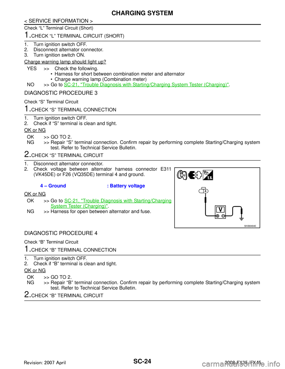
2. Check voltage between alternator harness connector E311 (VK45DE) or F26 (VQ35DE) terminal 4 and ground.
OK or NG
OK >> Go to SC-21, "Trouble Diagnosis with Starting/Charging
System Tester (Charging)".
NG >> Harness for open between alternator and fuse.
DIAGNOSTIC PROCEDURE 4
Check “B” Terminal Circuit
1.CHECK “B” TERMINAL CONNECTION
1. Turn ignition switch OFF.
2. Check if “B” terminal is clean and tight.
OK or NG
OK >> GO TO 2.
NG >> Repair “B” terminal connection. Confirm repair by performing complete Starting/Charging system
test. Refer to Technical Service Bulletin.
2.CHECK “B” TERMINAL CIRCUIT 4 – Ground : Battery voltage
SKIB8494E
3AA93ABC3ACD3AC03ACA3AC03AC63AC53A913A773A893A873A873A8E3A773A983AC73AC93AC03AC3
3A893A873A873A8F3A773A9D3AAF3A8A3A8C3A863A9D3AAF3A8B3A8C
Page 3634 of 3924
CHARGING SYSTEMSC-25
< SERVICE INFORMATION >
C
DE
F
G H
I
J
L
M A
B
SC
N
O P
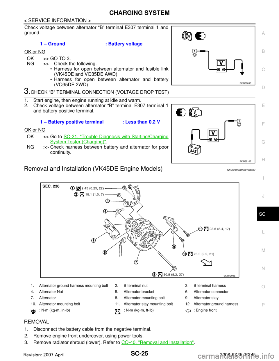
Check voltage between alternator “B” terminal E307 terminal 1 and
ground.
OK or NG
OK >> GO TO 3.
NG >> Check the following. Harness for open between alternator and fusible link
(VK45DE and VQ35DE AWD)
Harness for open between alternator and battery
(VQ35DE 2WD)
3.CHECK “B” TERMINAL CONNECT ION (VOLTAGE DROP TEST)
1. Start engine, then engine running at idle and warm.
2. Check voltage between alternator “B” terminal E307 terminal 1 and battery positive terminal.
OK or NG
OK >> Go to SC-21, "Trouble Diagnosis with Starting/Charging
System Tester (Charging)".
NG >> Check harness between battery and alternator for poor continuity.
Removal and Installation (VK45DE Engine Models)INFOID:0000000001328257
REMOVAL
1. Disconnect the battery cabl e from the negative terminal.
2. Remove engine front undercover, using power tools.
3. Remove radiator shroud (lower). Refer to CO-40, "
Removal and Installation".
1 – Ground : Battery voltage
PKIB8809E
1 – Battery positive terminal : Less than 0.2 V
PKIB8810E
1. Alternator ground harness mounting bolt 2. B terminal nut 3. B terminal harness
4. Alternator Nut 5. Alternator bracket 6. Alternator connector
7. Alternator 8. Alternator mounting bolt 9. Alternator stay
10. Alternator mounting bolt 11. Alternator stay mounting bolt 12. Alternator ground harness
: N·m (kg-m, in-lb) : N·m (kg-m, ft-lb) : Engine front
SKIB7209E
3AA93ABC3ACD3AC03ACA3AC03AC63AC53A913A773A893A873A873A8E3A773A983AC73AC93AC03AC3
3A893A873A873A8F3A773A9D3AAF3A8A3A8C3A863A9D3AAF3A8B3A8C
Page 3635 of 3924
SC-26
< SERVICE INFORMATION >
CHARGING SYSTEM
4. Remove alternator, water pump and A/C compressor belt. Refer to EM-170, "Removal and Installation".
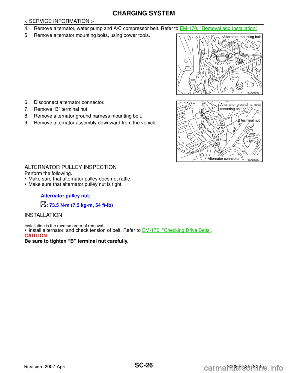
5. Remove alternator mounting bolts, using power tools.
6. Disconnect alternator connector.
7. Remove “B” terminal nut.
8. Remove alternator ground harness mounting bolt.
9. Remove alternator assembly downward from the vehicle.
ALTERNATOR PULLEY INSPECTION
Perform the following.
Make sure that alternator pulley does not rattle.
Make sure that alternator pulley nut is tight.
INSTALLATION
Installation is the reverse order of removal. Install alternator, and check tension of belt. Refer to EM-170, "Checking Drive Belts".
CAUTION:
Be sure to tighten “B” terminal nut carefully.
PKIA2954E
PKIA2820E
Alternator pulley nut:
: 73.5 N·m (7.5 kg-m, 54 ft-lb)
3AA93ABC3ACD3AC03ACA3AC03AC63AC53A913A773A893A873A873A8E3A773A983AC73AC93AC03AC3
3A893A873A873A8F3A773A9D3AAF3A8A3A8C3A863A9D3AAF3A8B3A8C
Page 3636 of 3924
CHARGING SYSTEMSC-27
< SERVICE INFORMATION >
C
DE
F
G H
I
J
L
M A
B
SC
N
O P
Removal and Installation (VQ35DE Engine Models)INFOID:0000000001328258
REMOVAL
1. Disconnect the battery cabl e from the negative terminal.
2. Remove engine front undercover, using power tools.
3. Remove alternator and power steering oil pump belt. Refer to EM-15, "
Removal and Installation".
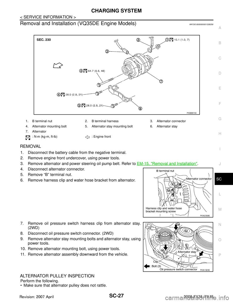
4. Disconnect alternator connector.
5. Remove “B” terminal nut.
6. Remove harness clip and water hose bracket from alternator.
7. Remove oil pressure switch harness clip from alternator stay. (2WD)
8. Disconnect oil pressure switch connector. (2WD)
9. Remove alternator stay mounting bolts and alternator stay, using power tools.
10. Remove alternator mounting bolt, using power tools.
11. Remove alternator assembly downward from the vehicle.
ALTERNATOR PULLEY INSPECTION
Perform the following.
Make sure that alternator pulley does not rattle.
1. B terminal nut 2. B terminal harness 3. Alternator connector
4. Alternator mounting bolt 5. Alternator stay mounting bolt 6. Alternator stay
7. Alternator
: N·m (kg-m, ft-lb) : Engine front
PKIB8815E
PKIA2358E
PKIA1923E
3AA93ABC3ACD3AC03ACA3AC03AC63AC53A913A773A893A873A873A8E3A773A983AC73AC93AC03AC3
3A893A873A873A8F3A773A9D3AAF3A8A3A8C3A863A9D3AAF3A8B3A8C
Page 3637 of 3924
SC-28
< SERVICE INFORMATION >
CHARGING SYSTEM
Make sure that alternator pulley nut is tight.
INSTALLATION
Installation is the reverse order of removal.
Install alternator, and check tension of belt. Refer to EM-14, "Checking Drive Belts".
CAUTION:
Be sure to tighten “B” terminal nut carefully.
Disassembly and AssemblyINFOID:0000000001328259
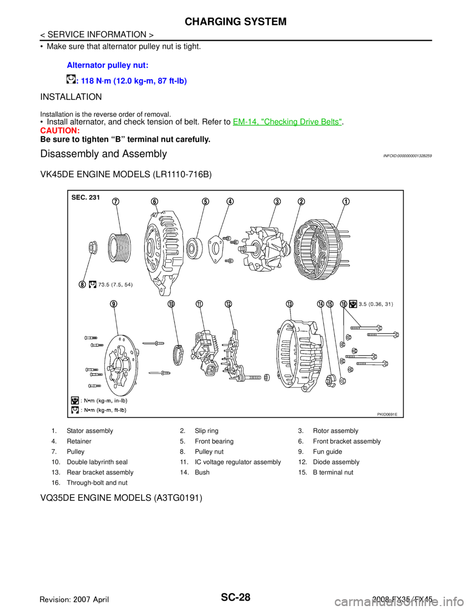
VK45DE ENGINE MODELS (LR1110-716B)
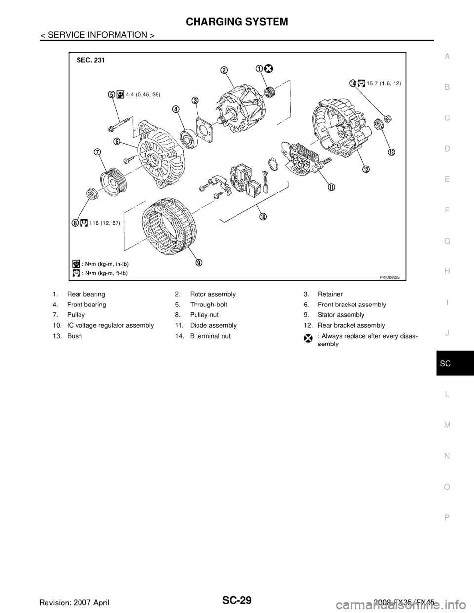
VQ35DE ENGINE MODELS (A3TG0191)
Alternator pulley nut:
: 118 N·m (12.0 kg-m, 87 ft-lb)
1. Stator assembly 2. Slip ring 3. Rotor assembly
4. Retainer 5. Front bearing 6. Front bracket assembly
7. Pulley 8. Pulley nut 9. Fun guide
10. Double labyrinth seal 11. IC voltage regulator assembly 12. Diode assembly
13. Rear bracket assembly 14. Bush 15. B terminal nut
16. Through-bolt and nut
PKID0691E
3AA93ABC3ACD3AC03ACA3AC03AC63AC53A913A773A893A873A873A8E3A773A983AC73AC93AC03AC3
3A893A873A873A8F3A773A9D3AAF3A8A3A8C3A863A9D3AAF3A8B3A8C
Page 3638 of 3924
CHARGING SYSTEMSC-29
< SERVICE INFORMATION >
C
DE
F
G H
I
J
L
M A
B
SC
N
O P
1. Rear bearing 2. Rotor assembly 3. Retainer
4. Front bearing 5. Through-bolt 6. Front bracket assembly
7. Pulley 8. Pulley nut 9. Stator assembly
10. IC voltage regulator assembly 11. Diode assembly 12. Rear bracket assembly
13. Bush 14. B terminal nut : Always replace after every disas- sembly
PKID0692E
3AA93ABC3ACD3AC03ACA3AC03AC63AC53A913A773A893A873A873A8E3A773A983AC73AC93AC03AC3
3A893A873A873A8F3A773A9D3AAF3A8A3A8C3A863A9D3AAF3A8B3A8C
Page 3825 of 3924
AIR BREATHER HOSETF-39
< SERVICE INFORMATION >
CEF
G H
I
J
K L
M A
B
TF
N
O P
AIR BREATHER HOSE
Removal and InstallationINFOID:0000000001327459
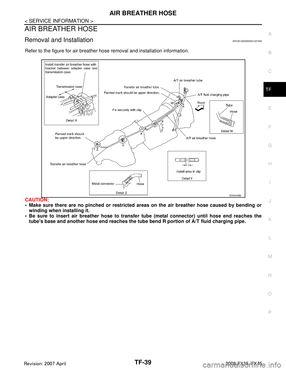
Refer to the figure for air breather hose removal and installation information.
CAUTION:
Make sure there are no pinched or restricted areas on the air breather hose caused by bending or
winding when installing it.
Be sure to insert air breather hose to transfer tube (metal connector) until hose end reaches the
tube's base and another hose end reaches the tube bend R portion of A/T fluid charging pipe.
SDIA2408E
3AA93ABC3ACD3AC03ACA3AC03AC63AC53A913A773A893A873A873A8E3A773A983AC73AC93AC03AC3
3A893A873A873A8F3A773A9D3AAF3A8A3A8C3A863A9D3AAF3A8B3A8C