checking oil INFINITI FX35 2008 Repair Manual
[x] Cancel search | Manufacturer: INFINITI, Model Year: 2008, Model line: FX35, Model: INFINITI FX35 2008Pages: 3924, PDF Size: 81.37 MB
Page 2712 of 3924
![INFINITI FX35 2008 Repair Manual
EM-228
< SERVICE INFORMATION >[VK45DE]
CYLINDER HEAD
4. Remove cylinder head bolts in reverse order as shown in the fig-
ure with cylinder head bolt wrench (commercial service tool) to
remove cylinde INFINITI FX35 2008 Repair Manual
EM-228
< SERVICE INFORMATION >[VK45DE]
CYLINDER HEAD
4. Remove cylinder head bolts in reverse order as shown in the fig-
ure with cylinder head bolt wrench (commercial service tool) to
remove cylinde](/img/42/57017/w960_57017-2711.png)
EM-228
< SERVICE INFORMATION >[VK45DE]
CYLINDER HEAD
4. Remove cylinder head bolts in reverse order as shown in the fig-
ure with cylinder head bolt wrench (commercial service tool) to
remove cylinder heads (right and left banks).
5. Remove cylinder head gaskets.
INSPECTION AFTER REMOVAL
Cylinder Head Bolt s Outer Diameter
Cylinder head bolts are tightened by plastic zone tightening
method. Whenever the size difference between “d1” and “d2”
exceeds the limit, replace them with new one.
If reduction of outer diameter appear s in a position other than “d2”,
use it as “d2” point.
Cylinder Head Distortion
NOTE:
When performing this inspection, cylinder block distortion should be also checking. Refer to EM-256, "
Inspec-
tion After Disassembly".
1. Using scraper, wipe off oil, scale, gasket, s ealant and carbon deposits from surface of cylinder head.
CAUTION:
Do not allow gasket fragme nts to enter engine oil or engine coolant passages.
2. At each of several locations on bottom surface of cylinder head, measure the distortion in six directions.
If it exceeds the limit, replace cylinder head.
INSTALLATION
1. Install new cylinder head gasket.
2. Turn crankshaft until No. 1 piston is set at TDC.
PBIC0068E
Limit (“d1” – “d2”) : 0.18 mm (0.0071 in)
PBIC2361E
Limit : 0.1 mm (0.004 in)
PBIC0075E
3AA93ABC3ACD3AC03ACA3AC03AC63AC53A913A773A893A873A873A8E3A773A983AC73AC93AC03AC3
3A893A873A873A8F3A773A9D3AAF3A8A3A8C3A863A9D3AAF3A8B3A8C
Page 2722 of 3924
![INFINITI FX35 2008 Repair Manual
EM-238
< SERVICE INFORMATION >[VK45DE]
ENGINE ASSEMBLY
1. Release fuel pressure. Refer to
EC-665, "Fuel Pressure Check".
2. Drain engine coolant from radiator. Refer to CO-37, "
Changing Engine Coo INFINITI FX35 2008 Repair Manual
EM-238
< SERVICE INFORMATION >[VK45DE]
ENGINE ASSEMBLY
1. Release fuel pressure. Refer to
EC-665, "Fuel Pressure Check".
2. Drain engine coolant from radiator. Refer to CO-37, "
Changing Engine Coo](/img/42/57017/w960_57017-2721.png)
EM-238
< SERVICE INFORMATION >[VK45DE]
ENGINE ASSEMBLY
1. Release fuel pressure. Refer to
EC-665, "Fuel Pressure Check".
2. Drain engine coolant from radiator. Refer to CO-37, "
Changing Engine Coolant".
CAUTION:
Perform this step when engine is cold.
Do not spill engine coolant on drive belts.
3. Disconnect both battery terminal. Refer to SC-4, "
How to Handle Battery".
4. Remove crankshaft position sensor (POS) from transmission. CAUTION:
Handle carefully to avoid dropping and shocks.
Do not disassemble.
Do not allow metal powder to adhere to magnetic part at sensor tip.
Do not place sensors in a location wh ere they are exposed to magnetism.
5. Remove the following parts: Hood assembly: Refer to BL-13, "
Fitting Adjustment".
Engine cover: Refer to EM-169
.
Front and rear engine undercover
Air duct (inlet), air duct and air cleaner case assembly: Refer to EM-173, "
Component".
Drive belts: Refer to EM-170, "
Component".
Radiator and radiator hoses (upper and lower): Refer to CO-40, "
Component".
Front road wheels and tires
Engine Room LH
1. Disconnect engine room harness from the engine side and set it aside for easier work.
2. Disconnect heater hoses, and install plugs to avoid leakage of engine coolant.
3. Disconnect ground cable from exhaust manifold cover to vehicle.
4. Disconnect vacuum hose between vehicle and engine and set it aside.
5. Discharge refrigerant from A/C circuit. Refer to ATC-120, "
HFC-134a (R-134a) Service Procedure".
6. Remove A/C piping from A/C compressor, and temporarily fasten it on vehicle with a rope. Refer to AT C -
121, "Component".
Engine Room RH
1. Disconnect fuel feed hose and EVAP hose. Refer to EM-190, "Component".
CAUTION:
Fit plugs onto disconnected hose to prevent fuel leak.
2. Disconnect engine room harness from the engine side and set it aside for easier work.
3. Disconnect ground cable from exhaust manifold cover to vehicle.
4. Disconnect vacuum hose between vehicle and engine and set it aside.
5. Disconnect reservoir tank of power steering oil pum p from engine, and move it aside for easier work.
CAUTION:
When temporarily securing, keep reservoir tank upright to avoid a fluid leak.
Vehicle Underbody
1. Remove front cross bar. Refer to FSU-5, "On-Vehicle Inspection and Service".
2. Disconnect power steering oil pump from engine. Move it from its location and secure with a rope for eas-
ier work. Refer to PS-29, "
Removal and Installation (VK45DE Models)".
3. Remove A/T fluid cooler tube. Refer to AT-241, "
Removal and Installation (2WD Models)".
4. Remove exhaust front tube and center muffler with power tool. Refer to EX-3, "
Checking Exhaust Sys-
tem".
5. Remove RH and LH transverse link mounting bolts and nuts. Refer to FSU-13, "
Removal and Installation".
6. Disconnect stabilizer connecting rod lower. Refer to FSU-5, "
On-Vehicle Inspection and Service".
7. Remove A/T control rod at control device assembly side. Then temporarily secure it on transmission, so
that it does not sag. Refer to AT-205, "
Control Device Removal and Installation".
8. Remove rear plate cover from oil pan. Then remove bolts fixing drive plate to torque converter. Refer to EM-183, "
Component" and AT-241, "Removal and Installation (2WD Models)".
9. Remove transmission joint bolts which pierce at oil pan lower rear side. Refer to AT-241, "
Removal and
Installation (2WD Models)".
3AA93ABC3ACD3AC03ACA3AC03AC63AC53A913A773A893A873A873A8E3A773A983AC73AC93AC03AC3
3A893A873A873A8F3A773A9D3AAF3A8A3A8C3A863A9D3AAF3A8B3A8C
Page 2724 of 3924
![INFINITI FX35 2008 Repair Manual
EM-240
< SERVICE INFORMATION >[VK45DE]
ENGINE ASSEMBLY
Avoid damage to and oil/grease smearing or
spills onto engine mounting insulator.
4. Remove alternator. Refer to SC-19, "
System Description INFINITI FX35 2008 Repair Manual
EM-240
< SERVICE INFORMATION >[VK45DE]
ENGINE ASSEMBLY
Avoid damage to and oil/grease smearing or
spills onto engine mounting insulator.
4. Remove alternator. Refer to SC-19, "
System Description](/img/42/57017/w960_57017-2723.png)
EM-240
< SERVICE INFORMATION >[VK45DE]
ENGINE ASSEMBLY
Avoid damage to and oil/grease smearing or
spills onto engine mounting insulator.
4. Remove alternator. Refer to SC-19, "
System Description".
5. Remove starter motor. Refer to SC-8, "
System Description".
6. Separate engine from transmission assembly. Refer to AT-243, "
Removal and Installation (AWD Models)".
7. Remove front final drive from engine. Refer to FFD-14, "
Removal and Installation (VQ35DE Models)".
8. Remove engine mounting insulators (RH and LH) and brackets (RH and LH) from engine with power tool.
9. Remove engine rear member and engine mounting insulator (rear) from transmission.
INSTALLATION
Note the following, and install in the reverse order of removal.
Do not allow engine mounting insulator to be damage and careful no engine oil gets on it.
For a location with a positioning pin, insert it securely into hole of mating part.
For a part with a specified installation orientation, refer to component figure in "Removal and Installation".
When installing engine mounting brackets (RH and LH) on cylinder
block, tighten two upper bolts (show n as “A” in the figure) first.
Then tighten two lower bolts (shown as “B” in the figure).
INSPECTION AFTER INSTALLATION
Inspection for Leaks
The followings are procedures for checking fluids leak, lubricates leak and exhaust gases leak.
Before starting engine, check oil/fluid levels incl uding engine coolant and engine oil. If less than required
quantity, fill to the specified level. Refer to MA-9, "
Fluids and Lubricants".
Use procedure below to check for fuel leakage.
- Turn ignition switch “ON” (with engine stopped). With fuel pressure applied to fuel piping, check for fuel leak-
age at connection points.
- Start engine. With engine speed increased, che ck again for fuel leakage at connection points.
Run engine to check for unusual noise and vibration.
Warm up engine thoroughly to make sure there is no leak age of fuel, exhaust gases, or any oil/fluids includ-
ing engine oil and engine coolant.
Bleed air from lines and hoses of applic able lines, such as in cooling system.
After cooling down engine, again check oil/fluid levels including engine oil and engine coolant. Refill to the specified level, if necessary.
Summary of the inspection items:
*: Transmission/transaxle/CVT fluid. power steering fluid, brake fluid, etc.
PBIC2365E
Items Before starting engine Engine running After engine stopped
Engine coolant Level Leakage Level
Engine oil Level Leakage Level
Other oils and fluid* Level Leakage Level
Fuel Leakage Leakage Leakage
Exhaust gases — Leakage —
3AA93ABC3ACD3AC03ACA3AC03AC63AC53A913A773A893A873A873A8E3A773A983AC73AC93AC03AC3
3A893A873A873A8F3A773A9D3AAF3A8A3A8C3A863A9D3AAF3A8B3A8C
Page 2792 of 3924

FFD-1
DRIVELINE/AXLE
CEF
G H
I
J
K L
M
SECTION FFD
A
B
FFD
N
O P
CONTENTS
FRONT FINAL DRIVE
SERVICE INFORMATION .. ..........................2
PRECAUTIONS .............................................. .....2
Service Notice or Precaution ............................... ......2
PREPARATION ...................................................3
Special Service Tool ........................................... ......3
Commercial Service Tool ..........................................5
NOISE, VIBRATION AND HARSHNESS
(NVH) TROUBLESHOOTING .............................
6
NVH Troubleshooting Chart ................................ ......6
DESCRIPTION ....................................................7
Cross-Sectional View .......................................... ......7
DIFFERENTIAL GEAR OIL .................................8
Changing Differential Gear Oil ............................ ......8
Checking Differential Gear Oil ............................. .....8
FRONT OIL SEAL ..............................................9
Removal and Installation ..........................................9
SIDE OIL SEAL .................................................12
Removal and Installation .........................................12
FRONT FINAL DRIVE ASSEMBLY ..................14
Removal and Installation (VQ35DE Models) ...........14
Removal and Installation (VK45DE Models) ...........15
Disassembly and Assembly .....................................17
SERVICE DATA AND SPECIFICATIONS
(SDS) .................................................................
39
General Specification ..............................................39
Inspection and Adjustment ......................................39
3AA93ABC3ACD3AC03ACA3AC03AC63AC53A913A773A893A873A873A8E3A773A983AC73AC93AC03AC3
3A893A873A873A8F3A773A9D3AAF3A8A3A8C3A863A9D3AAF3A8B3A8C
Page 2797 of 3924

FFD-6
< SERVICE INFORMATION >
NOISE, VIBRATION AND HARSHNESS (NVH) TROUBLESHOOTING
NOISE, VIBRATION AND HARSHNESS (NVH) TROUBLESHOOTING
NVH Troubleshooting ChartINFOID:0000000001327479
Use the chart below to help you find the cause of the sy mptom. If necessary, repair or replace these parts.
×: ApplicableReference page
Refer to
FFD-17, "
Disassembly and Assembly
".
Refer to FFD-17, "
Disassembly and Assembly
".
Refer to FFD-17, "
Disassembly and Assembly
".
Refer to FFD-17, "
Disassembly and Assembly
".
Refer to FFD-17, "
Disassembly and Assembly
".
Refer to FFD-8, "
Checking Differential Gear Oil
".
NVH in PR section.
NVH in FAX, RAX, FSU and RSU sections.
NVH in WT section.
NVH in WT section.
NVH in FAX and RAX section.
NVH in BR section.
NVH in PS section.
Possible cause and SUSPECTED PARTS
Gear tooth rough
Gear contact improper
Tooth surfaces worn
Backlash incorrect
Companion flange excessive runout
Gear oil improper
PROPELLER SHAFT
AXLE AND SUSPENSION
TIRE
ROAD WHEEL
DRIVE SHAFT
BRAKE
STEERING
Symptom Noise ×××××××××××××
3AA93ABC3ACD3AC03ACA3AC03AC63AC53A913A773A893A873A873A8E3A773A983AC73AC93AC03AC3
3A893A873A873A8F3A773A9D3AAF3A8A3A8C3A863A9D3AAF3A8B3A8C
Page 2799 of 3924

FFD-8
< SERVICE INFORMATION >
DIFFERENTIAL GEAR OIL
DIFFERENTIAL GEAR OIL
Changing Differential Gear OilINFOID:0000000001327481
DRAINING
1. Stop engine.
2. Remove drain plug (1) and drain gear oil.
3. Set a gasket on drain plug (1) and install it to final drive assem-bly and tighten to the specified torque. Refer to FFD-17, "
Disas-
sembly and Assembly", FFD-17, "Disassembly and Assembly".
CAUTION:
Never reuse gasket.
FILLING
1. Remove filler plug (1). Fill with new gear oil until oil level reaches the specified level near filler plug mounting hole.
2. After refilling oil, check oil level. Set a gasket to filler plug (1), then install it to final drive assembly. Refer to FFD-17, "
Disas-
sembly and Assembly", FFD-17, "Disassembly and Assembly".
CAUTION:
Never reuse gasket.
Checking Differential Gear OilINFOID:0000000001327482
OIL LEAKAGE AND OIL LEVEL
Make sure that oil is not leaking fr om final drive assembly or around it.
Remove filler plug (1) and check oil level from filler plug mounting hole as shown in the figure.
CAUTION:
Never start engine while checking oil level.
Set a gasket on filler plug (1) and install it on final drive assembly.
Refer to FFD-17, "
Disassembly and Assembly", FFD-17, "Disas-
sembly and Assembly".
CAUTION:
Never reuse gasket.
PDIA0781J
Oil grade and Viscosity:
Refer to MA-9, "
Fluids and Lubricants".
Oil capacity:
Approx. 0.65 (1-3/8 US pt, 1-1/8 Imp pt)
PDIA0782J
PDIA0782J
3AA93ABC3ACD3AC03ACA3AC03AC63AC53A913A773A893A873A873A8E3A773A983AC73AC93AC03AC3
3A893A873A873A8F3A773A9D3AAF3A8A3A8C3A863A9D3AAF3A8B3A8C
Page 2802 of 3924

FRONT OIL SEALFFD-11
< SERVICE INFORMATION >
CEF
G H
I
J
K L
M A
B
FFD
N
O P
9. Refill gear oil to the final drive and check oil level. Refer to FFD-8, "Changing Differential Gear Oil".
10. Check the final drive for oil leakage. Refer to FFD-8, "
Checking Differential Gear Oil".
3AA93ABC3ACD3AC03ACA3AC03AC63AC53A913A773A893A873A873A8E3A773A983AC73AC93AC03AC3
3A893A873A873A8F3A773A9D3AAF3A8A3A8C3A863A9D3AAF3A8B3A8C
Page 2804 of 3924

SIDE OIL SEALFFD-13
< SERVICE INFORMATION >
CEF
G H
I
J
K L
M A
B
FFD
N
O P
4. Install the front drive shaft. Refer to FAX-15, "Removal and Installation (Left Side)".
5. When oil leaks while removing, check oil level after the installation. Refer to FFD-8, "
Checking Differential
Gear Oil".
3AA93ABC3ACD3AC03ACA3AC03AC63AC53A913A773A893A873A873A8E3A773A983AC73AC93AC03AC3
3A893A873A873A8F3A773A9D3AAF3A8A3A8C3A863A9D3AAF3A8B3A8C
Page 2808 of 3924

FRONT FINAL DRIVE ASSEMBLYFFD-17
< SERVICE INFORMATION >
CEF
G H
I
J
K L
M A
B
FFD
N
O P
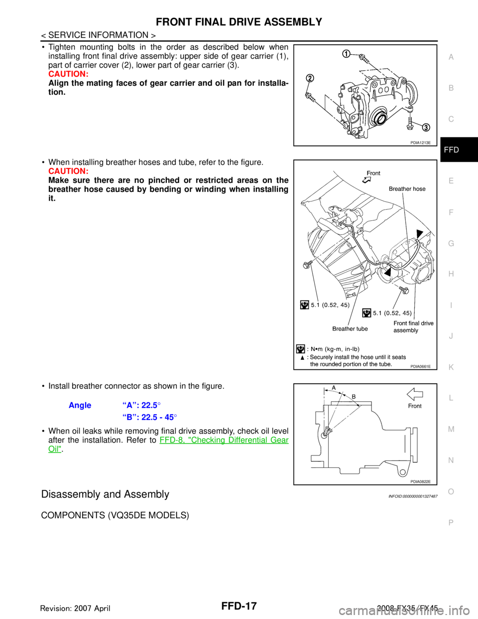
Tighten mounting bolts in the order as described below when installing front final drive assembly: upper side of gear carrier (1),
part of carrier cover (2), lower part of gear carrier (3).
CAUTION:
Align the mating faces of gear car rier and oil pan for installa-
tion.
When installing breather hoses and tube, refer to the figure. CAUTION:
Make sure there are no pinched or restricted areas on the
breather hose caused by bending or winding when installing
it.
Install breather connector as shown in the figure.
When oil leaks while removing final drive assembly, check oil level after the installation. Refer to FFD-8, "
Checking Differential Gear
Oil".
Disassembly and AssemblyINFOID:0000000001327487
COMPONENTS (VQ35DE MODELS)
PDIA1213E
PDIA0661E
Angle “A”: 22.5°
“B”: 22.5 - 45 °
PDIA0822E
3AA93ABC3ACD3AC03ACA3AC03AC63AC53A913A773A893A873A873A8E3A773A983AC73AC93AC03AC3
3A893A873A873A8F3A773A9D3AAF3A8A3A8C3A863A9D3AAF3A8B3A8C
Page 2842 of 3924

FL-10
< SERVICE INFORMATION >
FUEL TANK
FUEL TANK
ComponentINFOID:0000000001327110
Removal and InstallationINFOID:0000000001327111
REMOVAL
WARNING:
Be sure to read “General Precautions” when working on the fuel system. Refer to FL-3, "
General Pre-
caution".
Drain fuel from fuel tank if necessary. Refer to FL-4, "
Removal and Installation".
Perform work on level place.
1. Perform steps 2 to 7 of “REMOVAL” in “ FUEL LEVEL SENSOR UNIT, FUEL FILTER AND FUEL PUMP
ASSEMBLY” on main and sub fuel level sensor units. Refer to FL-4, "
Removal and Installation".
2. Remove tunnel stay. Refer to RSU-5, "
On-Vehicle Inspection and Service".
3. Remove exhaust front tube, center muffler and main muffler. Refer to EX-3, "
Checking Exhaust System".
4. Remove insulator.
5. Remove propeller shaft. Refer to PR-7, "
On-Vehicle Inspection".
6. Remove parking rear brake cables. Refer to PB-4, "
Component".
7. Compress coil spring and remove coil spring.
8. Remove rear suspension assembly.
9. Remove fuel tank protector.
1. Grommet 2. Fuel filler cap 3. Clip
4. Fuel filler tube protector 5. Fuel tank mounting band 6. Fuel tank protector
7. Insulator 8. Fuel tank 9. Vent tube
10. Vent hose 11. EVAP hose 12. Vent hose
13. Fuel filler hose 14. Fuel filler tube
PBIC1580E
3AA93ABC3ACD3AC03ACA3AC03AC63AC53A913A773A893A873A873A8E3A773A983AC73AC93AC03AC3
3A893A873A873A8F3A773A9D3AAF3A8A3A8C3A863A9D3AAF3A8B3A8C