run flat INFINITI FX35 2008 Service Manual
[x] Cancel search | Manufacturer: INFINITI, Model Year: 2008, Model line: FX35, Model: INFINITI FX35 2008Pages: 3924, PDF Size: 81.37 MB
Page 1007 of 3924
FRONT DISC BRAKEBR-23
< SERVICE INFORMATION >
C
DE
G H
I
J
K L
M A
B
BR
N
O P
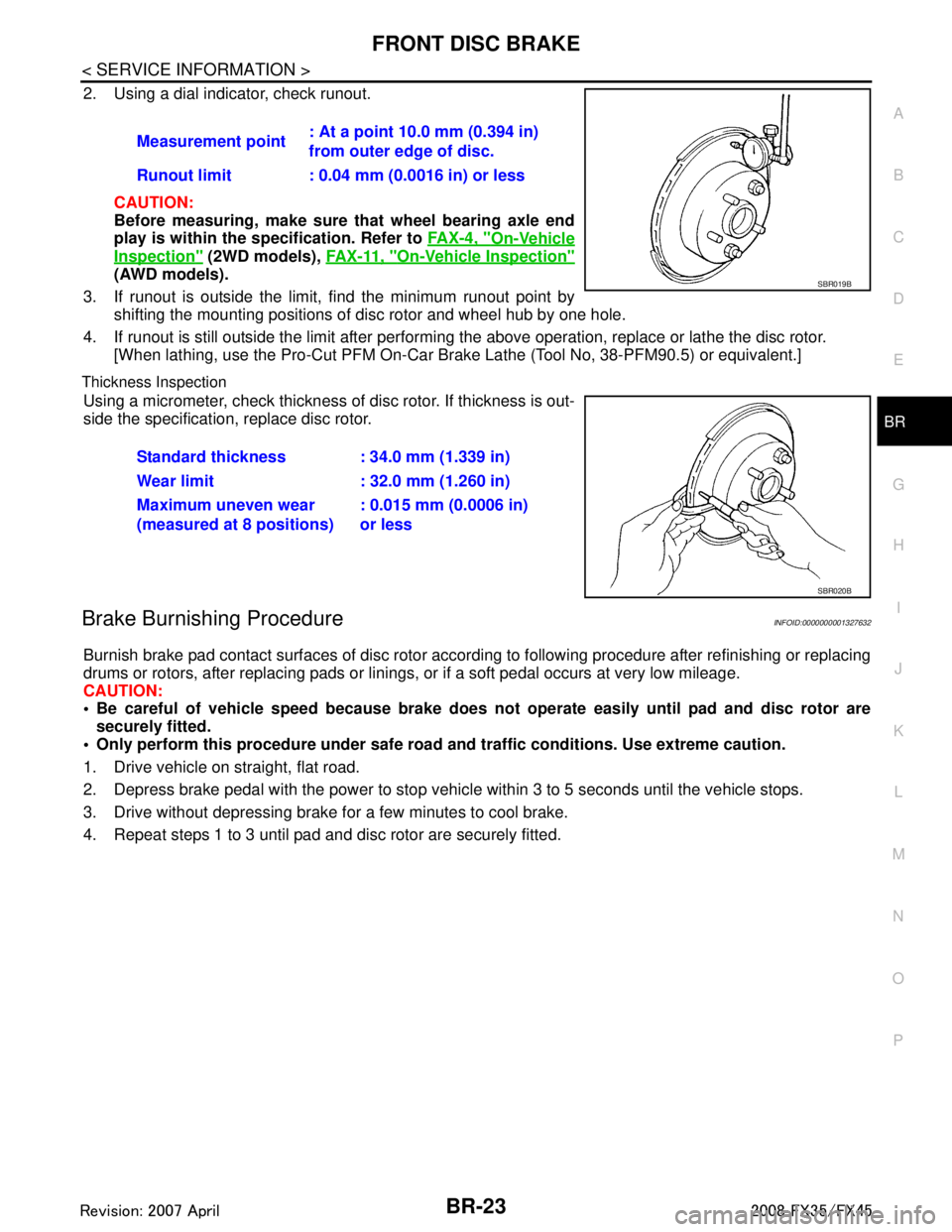
2. Using a dial indicator, check runout.
CAUTION:
Before measuring, make sure that wheel bearing axle end
play is within the sp ecification. Refer to FA X - 4 , "
On-Vehicle
Inspection" (2WD models), FA X - 11 , "On-Vehicle Inspection"
(AWD models).
3. If runout is outside the limit, find the minimum runout point by shifting the mounting positions of disc rotor and wheel hub by one hole.
4. If runout is still outside the limit after performing the above operation, replace or lathe the disc rotor.
[When lathing, use the Pro-Cut PFM On-Car Br ake Lathe (Tool No, 38-PFM90.5) or equivalent.]
Thickness Inspection
Using a micrometer, check thickness of disc rotor. If thickness is out-
side the specification, replace disc rotor.
Brake Burnishing ProcedureINFOID:0000000001327632
Burnish brake pad contact surfaces of disc rotor according to following procedure after refinishing or replacing
drums or rotors, after replacing pads or linings, or if a soft pedal occurs at very low mileage.
CAUTION:
Be careful of vehicle speed because brake does no t operate easily until pad and disc rotor are
securely fitted.
Only perform this procedure under safe road and traffic conditions. Use extreme caution.
1. Drive vehicle on straight, flat road.
2. Depress brake pedal with the power to stop vehicl e within 3 to 5 seconds until the vehicle stops.
3. Drive without depressing brake for a few minutes to cool brake.
4. Repeat steps 1 to 3 until pad and disc rotor are securely fitted. Measurement point
: At a point 10.0 mm (0.394 in)
from outer edge of disc.
Runout limit : 0.04 mm (0.0016 in) or less
SBR019B
Standard thickness : 34.0 mm (1.339 in)
Wear limit : 32.0 mm (1.260 in)
Maximum uneven wear
(measured at 8 positions) : 0.015 mm (0.0006 in)
or less
SBR020B
3AA93ABC3ACD3AC03ACA3AC03AC63AC53A913A773A893A873A873A8E3A773A983AC73AC93AC03AC3
3A893A873A873A8F3A773A9D3AAF3A8A3A8C3A863A9D3AAF3A8B3A8C
Page 1013 of 3924
REAR DISC BRAKEBR-29
< SERVICE INFORMATION >
C
DE
G H
I
J
K L
M A
B
BR
N
O P
4. If runout is still outside the limit after performing the above operation, replace or lathe the disc rotor.
[When lathing, use the Pro-Cut PFM On-Car Br ake Lathe (Tool No, 38-PFM90.5) or equivalent.]
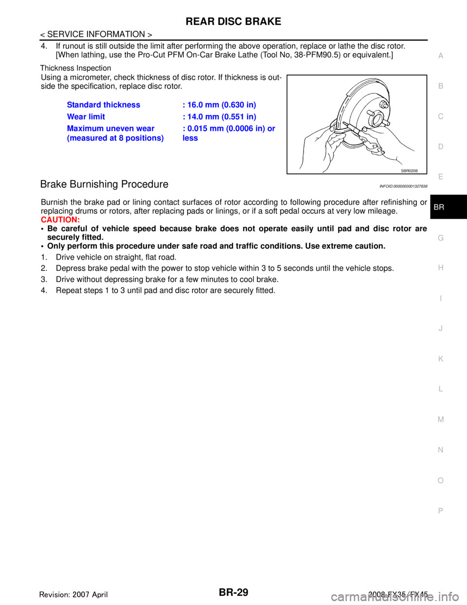
Thickness Inspection
Using a micrometer, check thickness of disc rotor. If thickness is out-
side the specification, replace disc rotor.
Brake Burnishing ProcedureINFOID:0000000001327638
Burnish the brake pad or lining contact surfaces of rotor according to following procedure after refinishing or
replacing drums or rotors, after replacing pads or li nings, or if a soft pedal occurs at very low mileage.
CAUTION:
Be careful of vehicle speed because brake does no t operate easily until pad and disc rotor are
securely fitted.
Only perform this procedure under safe road and traffic conditions. Use extreme caution.
1. Drive vehicle on straight, flat road.
2. Depress brake pedal with the power to stop vehicl e within 3 to 5 seconds until the vehicle stops.
3. Drive without depressing brake for a few minutes to cool brake.
4. Repeat steps 1 to 3 until pad and disc rotor are securely fitted. Standard thickness : 16.0 mm (0.630 in)
Wear limit : 14.0 mm (0.551 in)
Maximum uneven wear
(measured at 8 positions)
: 0.015 mm (0.0006 in) or
less
SBR020B
3AA93ABC3ACD3AC03ACA3AC03AC63AC53A913A773A893A873A873A8E3A773A983AC73AC93AC03AC3
3A893A873A873A8F3A773A9D3AAF3A8A3A8C3A863A9D3AAF3A8B3A8C
Page 1023 of 3924
![INFINITI FX35 2008 Service Manual
BRC-8
< SERVICE INFORMATION >[VDC/TCS/ABS]
ON-VEHICLE SERVICE
ON-VEHICLE SERVICE
Adjustment of Steering Angl
e Sensor Neutral PositionINFOID:0000000001327658
In case of doing work that applies to the INFINITI FX35 2008 Service Manual
BRC-8
< SERVICE INFORMATION >[VDC/TCS/ABS]
ON-VEHICLE SERVICE
ON-VEHICLE SERVICE
Adjustment of Steering Angl
e Sensor Neutral PositionINFOID:0000000001327658
In case of doing work that applies to the](/img/42/57017/w960_57017-1022.png)
BRC-8
< SERVICE INFORMATION >[VDC/TCS/ABS]
ON-VEHICLE SERVICE
ON-VEHICLE SERVICE
Adjustment of Steering Angl
e Sensor Neutral PositionINFOID:0000000001327658
In case of doing work that applies to the list below, make sure to adjust neutral position of steering angle sen-
sor before running vehicle.
CAUTION:
To adjust neutral position of steering angl e sensor, make sure to use CONSULT-III.
(Adjustment can not be done without CONSULT-III.)
1. Stop vehicle with front wheels in straight-ahead position.
2. Touch “WORK SUPPORT” and “ST ANGLE SENSOR ADJUSTMENT” on CONSULT-III screen in this order.
3. Touch “START”. CAUTION:
Do not touch steering wheel whil e adjusting steering angle sensor.
4. After approximately 10 seconds, touch “END”. (After approximately 60 seconds, it ends automatically.)
5. Turn ignition switch OFF, then turn it ON again. CAUTION:
Be sure to perform above operation.
6. Run vehicle with front wheels in straight-ahead position, then stop.
7. Select “DATA MONITOR”, “SELECTION FROM ME NU”, and “STR ANGLE SIG” on CONSULT-III screen.
Then make sure “STR ANGLE SIG” is within 0 ± 3.5 deg. If value is more than specification, repeat steps
1 to 6.
8. Erase memory of ABS actuator and electric unit (control unit) and ECM.
9. Turn ignition switch OFF.
Calibration of Decel G Sensor (AWD Models)INFOID:0000000001327659
NOTE:
After removing/installing or replacing yaw rate/side/dec el G sensor, ABS actuator and electric unit (control
unit), suspension components, or after adjusting wheel ali gnment, make sure to calibration of decel G sensor
before running vehicle.
CAUTION:
To calibrate decel G sensor, make sure to use CONS ULT-III. (Adjustment can not be done without CON-
SULT-III.)
1. Stop vehicle with front wheels in straight-ahead position.
CAUTION:
The work should be done at a horizontal place when vehicle is in the unloaded vehicle condition.
Keep all tires inflated to correct pressures. Ad just the tire pressure to the specified pressure
value.
2. Touch “WORK SUPPORT” and “DECEL G-SEN CALI BRATION” on CONSULT-III screen in this order.
3. Touch “START”. CAUTION:
Set vehicle as shown in the display.
4. After approximately 10 seconds, touch “END”. (After approximately 60 seconds, it ends automatically.)
Situation Adjustment of Steering Angle Sensor Neutral Position
Removing/Installing ABS actuator and electric unit (control unit) —
Replacing ABS actuator and electric unit (control unit) ×
Removing/Installing steering angle sensor ×
Removing/Installing steering components ×
Removing/Installing suspension components ×
Change 4 tires to new ones —
Tire rotation —
Adjusting wheel alignment ×
3AA93ABC3ACD3AC03ACA3AC03AC63AC53A913A773A893A873A873A8E3A773A983AC73AC93AC03AC3
3A893A873A873A8F3A773A9D3AAF3A8A3A8C3A863A9D3AAF3A8B3A8C
Page 1134 of 3924
DI-8
< SERVICE INFORMATION >
COMBINATION METERS
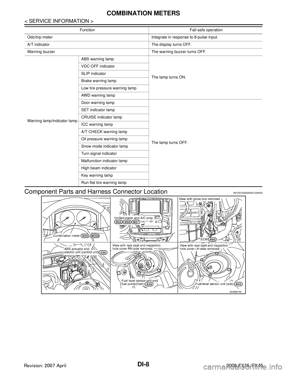
Component Parts and Harn ess Connector Location
INFOID:0000000001328434
Odo/trip meter Integrate in response to 8-pulse input.
A/T indicator The display turns OFF.
Warning buzzer The warning buzzer turns OFF.
Warning lamp/indicator lamp ABS warning lamp
The lamp turns ON.
VDC OFF indicator
SLIP indicator
Brake warning lamp
Low tire pressure warning lamp
AWD warning lamp
Door warning lamp
The lamp turns OFF.
SET indicator lamp
CRUISE indicator lamp
ICC warning lamp
A/T CHECK warning lamp
Oil pressure warning lamp
Snow mode indicator lamp
Turn signal indicator
Malfunction indicator lamp
High beam indicator
Key warning lamp
Run-flat tire warning lamp
Function Fail-safe operation
SKIB8474E
3AA93ABC3ACD3AC03ACA3AC03AC63AC53A913A773A893A873A873A8E3A773A983AC73AC93AC03AC3
3A893A873A873A8F3A773A9D3AAF3A8A3A8C3A863A9D3AAF3A8B3A8C
Page 1152 of 3924
DI-26
< SERVICE INFORMATION >
UNIFIED METER AND A/C AMP
UNIFIED METER AND A/C AMP
System DescriptionINFOID:0000000001328456
For the unified meter and A/C amp., the signal required for controlling the combination meter are integrated
in the A/C auto amp.
The unified meter and A/C amp. corresponds to a CONS ULT-III function (self-diagnosis results, CAN diag-
nosis support monitor, data monitor).
COMBINATION METER CONTROL FUNCTION
Unified meter and A/C amp. receives necessary information for combination meter from each unit by CAN communication.
Unified meter and A/C amp. transmits a signals with communication line (TX, RX) between unified meter and A/C amp. and combination meter.
Input/output signals between unified meter and A/C amp. and combination meter.
NOTE:
Combination meter performs fail-safe operation when unified meter and A/C amp. communication is malfunctioning. Refer to DI-5, "
Sys-
tem Description".
A/C AUTO AMP. FUNCTION
Unified meter and A/C amp. controls each operation for A/C auto amp. Regarding A/C control, refer to AT C -
24, "Description of Air Conditioner LAN Control System" in ATC section.
OTHER FUNCTIONS
Drive Computer Function
The signals required for the distance to empty (DTE) display are centralized in the unified meter and A/C
amp., converted into data, and transmitted to the disp lay unit (without NAVI) and display control unit (with
NAVI) using CAN communication.
Signal Buffer Function
Unified meter and A/C amp. transmits each signal to other units with CAN communication.
Unit Input Output
Unified meter and A/C amp. Seat belt buckle switch signal (Driver's side)
Parking brake signal
Illumination control nighttime required signal
Refuel status signal
Low-fuel warning lamp condition signal
Combination meter receive error signal
Delivery destination data signal
Combination meter specifications signal Vehicle speed signal (8-pulse)
Engine speed signal
Engine coolant temperature signal
Fuel level sensor signal (resistance value)
Malfunction indicator lamp signal
ABS warning lamp signal
Low tire pressure warning lamp signal
Run-flat tire wa
rning lamp signal
Brake warning lamp signal
A/T CHECK warning lamp signal
ICC warning lamp signal
Oil pressure switch signal
Door switch signal
AWD warning lamp signal
Key warning lamp signal
VDC OFF indicator lamp signal
SLIP indicator lamp signal
CRUISE indicator lamp signal
SET indicator lamp signal
High beam request signal
Turn indicator signal
Snow mode switch signal
ICC system display signal
Shift position indicator signal
Manual mode indicator signal
Manual mode gear position signal
CAN communication condition signal of A/T
Position lights request signal
Buzzer output signal
3AA93ABC3ACD3AC03ACA3AC03AC63AC53A913A773A893A873A873A8E3A773A983AC73AC93AC03AC3
3A893A873A873A8F3A773A9D3AAF3A8A3A8C3A863A9D3AAF3A8B3A8C
Page 1197 of 3924
LANE DEPARTURE WARNING SYSTEMDI-71
< SERVICE INFORMATION >
C
DE
F
G H
I
J
L
M A
B
DI
N
O P
NOTE:
*: This indicates in a few seconds for the system check during ignition switch ON.
POWER SUPPLY AND GROUND CIRCUIT
With the ignition switch in the ON or START position, power is supplied
through 10A fuse [No. 12, located in the fuse block (J/B)]
to LDW camera unit terminal 1.
Ground is supplied
to LDW camera unit terminals 6 and 12
through grounds M45, M85 and M35.
Action TestINFOID:0000000001328494
LDW SYSTEM RUNNING TEST
WARNING:
Be careful when performing road test.
Understand “Precautions” and “System Description” well before the road test. Refer to DI-69, "
Pre-
caution for Lane Departure Warning (LDW) system" and DI-69, "System Description".
Function Check
Check the LDW system operation according to the c ondition that the warning function works. Refer to DI-69,
"System Description".
Camera Aiming AdjustmentINFOID:0000000001328495
OUTLINE
Adjust the camera aiming every time the LDW camera unit is removed or installed.
CAUTION:
Place the vehicle on the level ground when the camera aiming adjustment is operated.
Follow the CONSULT-III when ad justing the camera aiming. (Camera aiming adjustment cannot be
operated without CONSULT-III.)
PREPARATION
Keep all tires inflated to correct pressures. Adjust the tire pressure to the specified pressure value.
There is no-load in vehicle. Check if coolant, engine oil are filled up to correct level and fuel tank is full.
Shift the gear into “P” position and release the parking brake.
Clean the windshield.
NOTE:
Do not place anything reflective on t he upper surface of instrument panel.
TARGET SETTING
Preparation Aiming Adjustment Jig
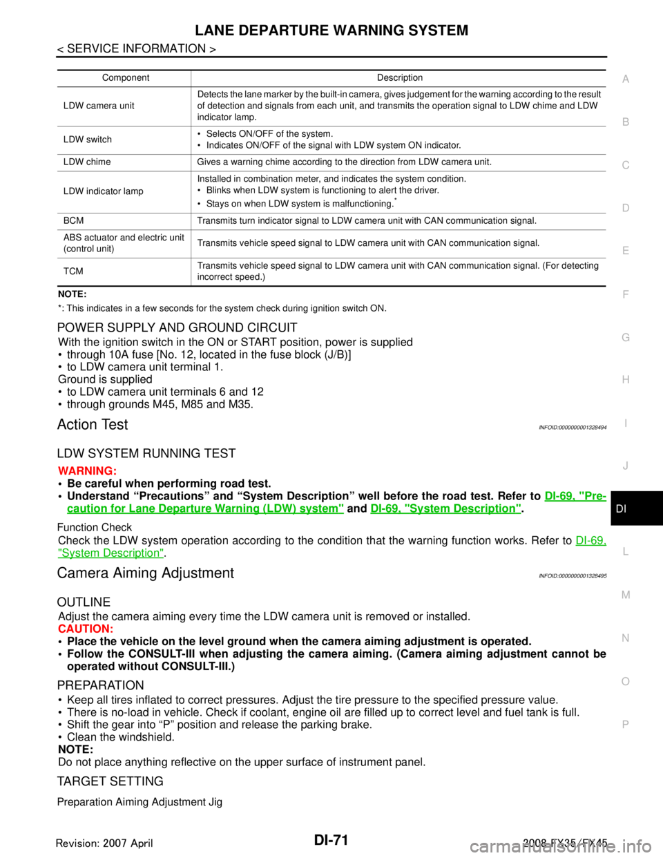
Component Description
LDW camera unit Detects the lane marker by the built-in camera, gives judgement for the warning according to the result
of detection and signals from each unit, and transmits the operation signal to LDW chime and LDW
indicator lamp.
LDW switch Selects ON/OFF of the system.
Indicates ON/OFF of the signal with LDW system ON indicator.
LDW chime Gives a warning chime according to the direction from LDW camera unit.
LDW indicator lamp Installed in combination meter, and indicates the system condition.
Blinks when LDW system is functioning to alert the driver.
Stays on when LDW system is malfunctioning.
*
BCM Transmits turn indicator signal to LDW camera unit with CAN communication signal.
ABS actuator and electric unit
(control unit)
Transmits vehicle speed signal to LDW camera unit with CAN communication signal.
TCM Transmits vehicle speed signal to LDW camera unit with CAN communication signal. (For detecting
incorrect speed.)
3AA93ABC3ACD3AC03ACA3AC03AC63AC53A913A773A893A873A873A8E3A773A983AC73AC93AC03AC3
3A893A873A873A8F3A773A9D3AAF3A8A3A8C3A863A9D3AAF3A8B3A8C
Page 2483 of 3924
EI-46
< SERVICE INFORMATION >
LUGGAGE FLOOR TRIM
Removal and Installation
INFOID:0000000001529413
REMOVAL
1. Remove tonneau cover.
2. Remove luggage side hook and remove net hook (RH/LH).
3. Remove luggage floor board assembly. Remove bolt with power tool.
4. Remove luggage floor side board assembly (RH/LH).
5. Remove back door weather strip.
6. Remove rear plate assembly.
7. Remove roof rear garnish assembly.
8. Remove luggage floor cover assembly (RH/LH).
9. Remove rear door kicking plate (RH/LH).
10. Remove rear body side welt.
11. Remove rear seat cushion and seatback. Refer to SE-95, "
Removal and Installation".
12. Remove rear wheel house finisher assembly (RH/LH).
13. Remove luggage side finisher assembly bolt and remove luggage side finisher assembly (RH/LH).
14. Remove bolt, and then remove parcel shelf holder.
15. Remove rear parcel shelf cap.
16. Remove bolt, and then remove rear parcel hook.
17. Remove rear seat belt anchor (RH/LH). Refer to SB-5, "
Removal and Installation of Rear Seat Belt".
18. Remove rear pillar upper garnish assembly cap and bolt, then remove rear pillar upper garnish assembly (RH/LH).
19. Remove spare tire clamp.
20. Remove sub-woofer box connector and remove sub-woofer box.
21. Remove spare tire.
22. Remove towing hook, wheel nut wrench, spanner, tire stopper, jack rod and jack complete.
23. Remove luggage side box bolt and luggage side box assembly (RH/LH).
INSTALLATION
Install in the reverse order of removal.
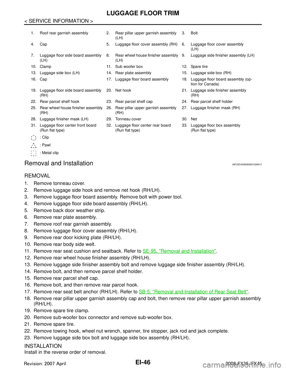
1. Roof rear garnish assembly 2. Rear pillar upper garnish assembly (LH)3. Bolt
4. Cap 5. Luggage floor cover assembly (RH) 6. Luggage floor cover assembly (LH)
7. Luggage floor side board assembly (LH) 8. Rear wheel house finisher assembly
(LH) 9. Luggage side finisher assembly (LH)
10. Clamp 11. Sub woofer box 12. Spare tire
13. Luggage side box (LH) 14. Rear plate assembly 15. Luggage side box (RH)
16. Cap 17. Luggage floor board assembly 18. Luggage floor board assembly (op- tion for Canada)
19. Luggage floor side board assembly (RH) 20. Net hook 21. Luggage side finisher assembly
(RH)
22. Rear parcel shelf hook 23. Rear parcel shelf cap 24. Rear parcel shelf holder
25. Rear wheel house finisher assembly (RH) 26. Rear pillar upper garnish assembly
(RH) 27. Luggage finisher mask (RH)
28. Luggage finisher mask (LH) 29. Tonneau cover 30. Net
31. Luggage floor center front board (Run flat type) 32. Luggage floor center rear board
(Run flat type) 33. Luggage floor box assembly
(Run flat type)
: Clip
: Pawl
: Metal clip
3AA93ABC3ACD3AC03ACA3AC03AC63AC53A913A773A893A873A873A8E3A773A983AC73AC93AC03AC3
3A893A873A873A8F3A773A9D3AAF3A8A3A8C3A863A9D3AAF3A8B3A8C
Page 2569 of 3924
![INFINITI FX35 2008 Service Manual
CAMSHAFTEM-85
< SERVICE INFORMATION > [VQ35DE]
C
D
E
F
G H
I
J
K L
M A
EM
NP
O
6. Remove valve lifter.
Identify installation positions, and store them without mixing them up.
7. Remove timing chain INFINITI FX35 2008 Service Manual
CAMSHAFTEM-85
< SERVICE INFORMATION > [VQ35DE]
C
D
E
F
G H
I
J
K L
M A
EM
NP
O
6. Remove valve lifter.
Identify installation positions, and store them without mixing them up.
7. Remove timing chain](/img/42/57017/w960_57017-2568.png)
CAMSHAFTEM-85
< SERVICE INFORMATION > [VQ35DE]
C
D
E
F
G H
I
J
K L
M A
EM
NP
O
6. Remove valve lifter.
Identify installation positions, and store them without mixing them up.
7. Remove timing chain tensioner (secondary) from cylinder head. Remove timing chain tensioner (secondary) with its stopperpin attached.
NOTE:
Stopper pin was attached when timing chain (secondary) was
removed.
INSPECTION AFTER REMOVAL
Camshaft Runout
1. Put V-block on precise flat table, and support No. 2 and 4 jour- nals of camshaft.
CAUTION:
Do not support No. 1 journal (on the side of camshaft
sprocket) because it has a different diameter from the other
three locations.
2. Set a dial indicator vertically to No. 3 journal.
3. Turn camshaft to one direction with hands, and measure the camshaft runout on a dial indicator. (Total indicator reading)
4. If it exceeds the limit, replace camshaft.
Camshaft Cam Height
1. Measure the camshaft cam height with a micrometer.
2. If wear exceeds the limit, replace camshaft.
Camshaft Journa l Oil Clearance
CAMSHAFT JOURNAL DIAMETER
Measure the outer diameter of camshaft journal with a micrometer.
PBIC2111E
Standard : Less than 0.02 mm (0.0008 in)
Limit : 0.05 mm (0.0020 in)PBIC0929E
Standard cam height (intake and exhaust)
: 44.865 - 45.055 mm (1.7663 - 1.7738 in)
Cam wear limit : 0.2 mm (0.008 in)
EMQ0072D
Standard:No. 1 : 25.935 - 25.955 mm (1.0211 - 1.0218 in)
No. 2, 3, 4 : 23.445 - 23.465 mm (0.9230 - 0.9238 in)
PBIC0040E
3AA93ABC3ACD3AC03ACA3AC03AC63AC53A913A773A893A873A873A8E3A773A983AC73AC93AC03AC3
3A893A873A873A8F3A773A9D3AAF3A8A3A8C3A863A9D3AAF3A8B3A8C
Page 2570 of 3924
![INFINITI FX35 2008 Service Manual
EM-86
< SERVICE INFORMATION >[VQ35DE]
CAMSHAFT
CAMSHAFT BRACKET INNER DIAMETER
Tighten camshaft bracket bolt with the specified tor que. Refer to "INSTALLATION" for the tightening proce-
dure.
M INFINITI FX35 2008 Service Manual
EM-86
< SERVICE INFORMATION >[VQ35DE]
CAMSHAFT
CAMSHAFT BRACKET INNER DIAMETER
Tighten camshaft bracket bolt with the specified tor que. Refer to "INSTALLATION" for the tightening proce-
dure.
M](/img/42/57017/w960_57017-2569.png)
EM-86
< SERVICE INFORMATION >[VQ35DE]
CAMSHAFT
CAMSHAFT BRACKET INNER DIAMETER
Tighten camshaft bracket bolt with the specified tor que. Refer to "INSTALLATION" for the tightening proce-
dure.
Measure inner diameter “A” of camshaft bracket with a bore gauge.
CAMSHAFT JOURNA L OIL CLEARANCE (Oil clearance) = (Camshaft bracket inner diameter) – (Camshaft journal diameter).
If the calculated value exceeds the limit, replace either or both camshaft and cylinder head.
NOTE:
Camshaft brackets cannot be replaced as single part s, because there are machined together with cylinder
head. Replace whole cylinder head assembly.
Camshaft End Play
Install a dial indicator in thrust direction on front end of camshaft. Measure the end play of a dial indicator when camshaft is moved
forward/backward (in direction to axis).
Measure the following parts if out of the limit.
- Dimension “A” for camshaft No. 1 journal
- Dimension “B” for cylinder head No. 1 journal bearing
Refer to the standards above, and then replace camshaft and/or cylinder head.
Camshaft Sprocket Runout
1. Put V-block on precise flat table, and support No. 2 and 4 journals of camshaft. CAUTION:
Do not support No. 1 journal (on the side of cam shaft sprocket) because it has a different diameter
from the other three locations. Standard:
No. 1 : 26.000 - 26.021 mm (1.0236 - 1.0244 in)
No. 2, 3, 4 : 23.500 - 23.521 mm (0.9252 - 0.9260 in)
PBIC1645E
Standard:No. 1 : 0.045 - 0.086 mm (0.0018 - 0.0034 in)
No. 2, 3, 4 : 0.035 - 0.076 mm (0.0014 - 0.0030 in)
Limit : 0.15 mm (0.0059 in)
Standard : 0.115 - 0.188 mm (0.0045 - 0.0074 in)
Limit : 0.24 mm (0.0094 in)
SEM864E
Standard : 27.500 - 27.548 mm (1.0827 - 1.0846 in)
Standard : 27.360 - 27.385 mm (1.0772 - 1.0781 in)
KBIA2404J
3AA93ABC3ACD3AC03ACA3AC03AC63AC53A913A773A893A873A873A8E3A773A983AC73AC93AC03AC3
3A893A873A873A8F3A773A9D3AAF3A8A3A8C3A863A9D3AAF3A8B3A8C
Page 2629 of 3924
![INFINITI FX35 2008 Service Manual
CYLINDER BLOCKEM-145
< SERVICE INFORMATION > [VQ35DE]
C
D
E
F
G H
I
J
K L
M A
EM
NP
O
Measure the outer diameter of crankshaft pin journal with a
micrometer.
If out of the standard, measure the c INFINITI FX35 2008 Service Manual
CYLINDER BLOCKEM-145
< SERVICE INFORMATION > [VQ35DE]
C
D
E
F
G H
I
J
K L
M A
EM
NP
O
Measure the outer diameter of crankshaft pin journal with a
micrometer.
If out of the standard, measure the c](/img/42/57017/w960_57017-2628.png)
CYLINDER BLOCKEM-145
< SERVICE INFORMATION > [VQ35DE]
C
D
E
F
G H
I
J
K L
M A
EM
NP
O
Measure the outer diameter of crankshaft pin journal with a
micrometer.
If out of the standard, measure the connecting rod bearing oil clearance. Then use undersize bearing. Refer to "CONNECTING
ROD BEARING OIL CLEARANCE".
CRANKSHAFT OUT-OF-ROUND AND TAPER
Measure the dimensions at four different points as shown in thefigure on each main journal and pin journal with a micrometer.
Out-of-round is indicated by t he difference in the dimensions
between “X” and “Y” at “A” and “B”.
Taper is indicated by the difference in the dimensions between “A” and “B” at “X” and “Y”.
If the measured value exceeds the li mit, correct or replace crankshaft.
If corrected, measure the bearing oil clearance of the corrected main journal and/or pin journal. Then select the main bearing and/or connecting rod bearing. Refer to "MAIN BEARING OIL CLEARANCE" and/or
"CONNECTING ROD BEARING OIL CLEARANCE".
CRANKSHAFT RUNOUT
Place V-block on precise flat table, and support the journals on the both end of crankshaft.
Place a dial indicator straight up on the No. 3 journal.
While rotating crankshaft, read the movement of the pointer on a dial indicator. (Total indicator reading)
If it exceeds the limit, replace crankshaft.
CONNECTING ROD BEARING OIL CLEARANCE
Method by Calculation
Install connecting rod bearings to connecting rod and connecting rod cap, and tighten connecting rod bolts to the specified torque.
Refer to EM-123, "
Disassembly and Assembly" for the tightening
procedure.
Measure the inner diameter of connecting rod bearing with an
inside micrometer.
(Oil clearance) = (Connecting rod bearing inner diameter) – (Crank-
shaft pin journal diameter) Standard : 51.956 - 51.974 mm (2.0455 - 2.0462 in) dia.
PBIC0127E
Limit:
Out-of-round (Differen ce between “X” and “Y”)
: 0.002 mm (0.0001 in)
Taper (Difference between “A” and “B”) : 0.002 mm (0.0001 in)
SBIA0535E
Standard : Less than 0.05 mm (0.0020 in)
Limit : 0.10 mm (0.0039 in)
SEM346D
Standard : 0.034 - 0.059 mm (0.0013 - 0.0023 in) (actual clearance)
Limit : 0.070 mm (0.0028 in)
PBIC1642E
3AA93ABC3ACD3AC03ACA3AC03AC63AC53A913A773A893A873A873A8E3A773A983AC73AC93AC03AC3
3A893A873A873A8F3A773A9D3AAF3A8A3A8C3A863A9D3AAF3A8B3A8C