clock INFINITI FX35 2008 Repair Manual
[x] Cancel search | Manufacturer: INFINITI, Model Year: 2008, Model line: FX35, Model: INFINITI FX35 2008Pages: 3924, PDF Size: 81.37 MB
Page 3013 of 3924
![INFINITI FX35 2008 Repair Manual
IP-12
< SERVICE INFORMATION >
INSTRUMENT PANEL ASSEMBLY
[]: Number indicates step in removal procedures.
REMOVAL
(A) Front Kicking Plate (RH/LH)
Remove front kicking plate (RH/LH). Refer to EI-38.
(B INFINITI FX35 2008 Repair Manual
IP-12
< SERVICE INFORMATION >
INSTRUMENT PANEL ASSEMBLY
[]: Number indicates step in removal procedures.
REMOVAL
(A) Front Kicking Plate (RH/LH)
Remove front kicking plate (RH/LH). Refer to EI-38.
(B](/img/42/57017/w960_57017-3012.png)
IP-12
< SERVICE INFORMATION >
INSTRUMENT PANEL ASSEMBLY
[]: Number indicates step in removal procedures.
REMOVAL
(A) Front Kicking Plate (RH/LH)
Remove front kicking plate (RH/LH). Refer to EI-38.
(B) Dash Side Finisher (RH/LH)
1. Remove plastics nut.
2. Remove dash side finisher (RH/LH). Refer to EI-38
.
(C) Front Pillar Garnish (RH/LH)
Pull to inside of vehicle, disengage metal clips and remove front pillar garnish. Refer to EI-38.
(D) A/T Select Lever Knob
1. Pull down knob cover.
2. Remove lock-pin of select lever knob.
3. Lift up select lever knob and remove select lever knob.
Refer to AT-205, "
Control Device Removal and Installation".
(E) Instrument Clock Finisher
1. Remove screw and then pull back to your side of instrument
clock finisher.
2. Disconnect clips and harness connector, and remove instrument clock finisher.
(F) A/T Console Finisher
(O) Wiper and washer switch (O) Wiper and
Washer Switch [15] [7]
(P) Lighting and turn signal switch (P) Lighting and
Turn Signal Switch [16] [8]
(Q) Steering lock escutcheon (Q) Steering Lock
Escutcheon [17] [9]
(R) Combination meter assembly (R) Combination
Meter Assembly [18] [10]
(S) Cluster lid C (S) Cluster Lid C [19] [1] (T) Display unit and audio unit (T) Display Unit
and Audio Unit [20] [2]
(U) Front defroster grille (RH/LH) (U) Front
Defroster Grille (RH/LH) [21]
(V) Combination meter bracket (V) Combination
Meter Bracket [22]
(W) Side ventilation (RH/LH) (W) Side
Ventilation (RH/LH) [23]
(X) Instrument panel and pad (X) Instrument
Panel and Pad [24]
Parts
Reference
page Instrument
panel and pad Combination
meter Display unit
and audio unit Center console
: Clip
: Pawl
PIIB8535E
3AA93ABC3ACD3AC03ACA3AC03AC63AC53A913A773A893A873A873A8E3A773A983AC73AC93AC03AC3
3A893A873A873A8F3A773A9D3AAF3A8A3A8C3A863A9D3AAF3A8B3A8C
Page 3018 of 3924

INSTRUMENT PANEL ASSEMBLYIP-17
< SERVICE INFORMATION >
C
DE
F
G H
J
K L
M A
B
IP
N
O P
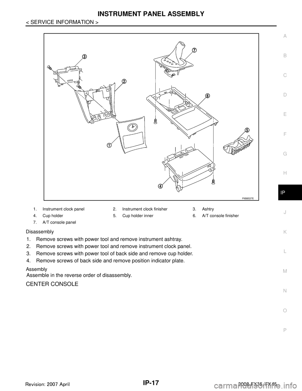
Disassembly
1. Remove screws with power tool and remove instrument ashtray.
2. Remove screws with power tool and remove instrument clock panel.
3. Remove screws with power tool of back side and remove cup holder.
4. Remove screws of back side and remove position indicator plate.
Assembly
Assemble in the reverse order of disassembly.
CENTER CONSOLE
1. Instrument clock panel 2. Instrument clock finisher 3. Ashtry
4. Cup holder 5. Cup holder inner 6. A/T console finisher
7. A/T console panel
PIIB8537E
3AA93ABC3ACD3AC03ACA3AC03AC63AC53A913A773A893A873A873A8E3A773A983AC73AC93AC03AC3
3A893A873A873A8F3A773A9D3AAF3A8A3A8C3A863A9D3AAF3A8B3A8C
Page 3131 of 3924

HEADLAMP - XENON TYPE -LT-29
< SERVICE INFORMATION >
C
DE
F
G H
I
J
L
M A
B
LT
N
O P
1. Turn lighting switch OFF.
2. Disconnect the battery cable from the negative terminal or remove power fuse.
3. Remove air cleaner case (when replacing LH bulb). Refer to EM-173
(VK45) or refer to EM-17 (VQ35).
4. Remove radiator reservoir tank (when replacing RH bulb). Refer to CO-40
(VK45) or refer to CO-13 (VQ35).
5. Turn plastic cap counterclockwise and unlock it.
6. Turn bulb socket counterclockwise and unlock it.
7. Unlock retaining spring and remove bulb from headlamp.
8. Installation is the reverse order of removal. NOTE:
After installation, perform aiming adjustment. Refer to LT-27, "
Aiming Adjustment".
DAYTIME/PARKING LAMP
1. Turn lighting switch OFF.
2. Remove air cleaner case (when replacing LH bulb of VK45).
Refer to EM-173
.
3. Turn bulb socket counterclockwise and unlock it.
4. Remove bulb from its socket.
5. Installation is the reverse order of removal.
FRONT TURN SIGNAL LAMP
1. Turn lighting switch OFF.
2. Turn bulb socket counterclockwise with suitable tool and unlock it.
3. Remove bulb from its socket.
4. Installation is the reverse order of removal.
FRONT SIDE MARKER LAMP
1. Turn lighting switch OFF.
2. Turn bulb socket counterclockwise and unlock it.
3. Remove bulb from its socket.
4. Installation is the reverse order of removal.
CAUTION:Headlamp high/low beam (Xenon) : 12 V - 35 W (D2S)
PKIC9730E
Daytime/Parking lamp : 12 V - 21/5 W
PKIC9732E
Front turn signal lamp : 12 V - 21 W (amber)
SKIA6182E
Front side marker lamp : 12 V - 3.8 W
SKIA5552E
3AA93ABC3ACD3AC03ACA3AC03AC63AC53A913A773A893A873A873A8E3A773A983AC73AC93AC03AC3
3A893A873A873A8F3A773A9D3AAF3A8A3A8C3A863A9D3AAF3A8B3A8C
Page 3132 of 3924

LT-30
< SERVICE INFORMATION >
HEADLAMP - XENON TYPE -
After installing bulb, be sure to install plastic cap and bulb socket securely to insure watertight-
ness.
Removal and InstallationINFOID:0000000001328289
REMOVAL
1. Disconnect the battery cable from the negative terminal or remove power fuse.
2. Remove front bumper fascia assembly. Refer to EI-14, "
Compo-
nent Parts Location".
3. Remove headlamp mounting bolts and nut.
4. Remove plastics bumper bracket, then pull headlamp toward vehicle front, disconnect connector, and remove headlamp.
INSTALLATION
Installation is the reverse order of removal.
NOTE:
After installation, perform aiming adjustment. Refer to LT-27, "
Aiming Adjustment".
Disassembly and AssemblyINFOID:0000000001328290
DISASSEMBLY
1. Turn plastic cap counterclockwise and unlock it.
SKIA5553E
Headlamp mounting bolt : 6.1 N·m (0.62 kg-m, 54 in-lb)
1. Side marker lamp bulb 2. Side marker lamp bulb socket 3. Front turn signal lamp bulb socket
4. Front turn signal lamp bulb 5. Seal packing 6. Plastic cap
7. Xenon bulb (high/low) 8. Xenon bulb socket (high/low) 9. HID control unit cover mounting screw
10. HID control unit cover 11. HID control unit mounting screw 12. HID control unit
13. Seal packing 14. Daytime/Parking lamp bulb socket 15. Daytime/Parking lamp bulb
16. Headlamp housing assembly 17. Retaining spring
:Alway replace after every disassembly
:N·m (kg-m, in-lb)
PKIC9685E
3AA93ABC3ACD3AC03ACA3AC03AC63AC53A913A773A893A873A873A8E3A773A983AC73AC93AC03AC3
3A893A873A873A8F3A773A9D3AAF3A8A3A8C3A863A9D3AAF3A8B3A8C
Page 3133 of 3924

HEADLAMP - XENON TYPE -LT-31
< SERVICE INFORMATION >
C
DE
F
G H
I
J
L
M A
B
LT
N
O P
2. Turn xenon bulb socket count erclockwise, and unlock it.
3. Unlock retaining spring, and remove xenon bulb (high/low).
4. Remove HID control unit cover mounting screw.
5. Remove HID control unit cover.
6. Disconnect HID control unit connector.
7. Remove HID control unit mounting screws.
8. Remove HID control unit.
9. Turn daytime/parking lamp bulb socket counterclockwise and unlock it.
10. Remove daytime/parking lamp bulb from its socket.
11. Turn front turn signal lamp bulb socket counterclockwise and unlock it.
12. Remove front turn signal lamp bulb from its socket.
13. Turn front side marker lamp bulb socket counterclockwise and unlock it.
14. Remove front side marker lamp bulb from its socket.
ASSEMBLY
Assembly is the reverse order of disassembly.
CAUTION:
When HID control unit is removed, rein stall it securely and avoid any looseness.
After installing bulb, be sure to install plastic cap and bulb socket securely to insure watertightness.
HID control unit mounting screw
: 3.2 N·m (0.33 kg-m, 28 in-lb)
3AA93ABC3ACD3AC03ACA3AC03AC63AC53A913A773A893A873A873A8E3A773A983AC73AC93AC03AC3
3A893A873A873A8F3A773A9D3AAF3A8A3A8C3A863A9D3AAF3A8B3A8C
Page 3178 of 3924

LT-76
< SERVICE INFORMATION >
FRONT FOG LAMP
3. Adjust front fog lamps using adjusting screw so that the top edgeof the high intensity zone is 100 mm (3.94 in) below the height of
front fog lamp centers as shown at left.
When performing adjustment, if necessary, cover headlampsand opposite front fog lamp.
Bulb ReplacementINFOID:0000000001328341
1. Remove fender protector (front). Refer to EI-24, "Component
Parts Location", EI-14, "Component Parts Location".
2. Disconnect front fog lamp connector.
3. Turn bulb socket counterclockwise and unlock it.
CAUTION:
Never touch the glass of bulb directly by hand. Keepgrease and other oily matters away from it. Never touch
bulb by hand while it is lit or right after being turned off.
Burning may result.
Never leave bulb out of front fog lamp reflector for a long time because dust, moisture smoke,
etc. May affect the performance of front fog lamp . When replacing bulb, be sure to replace it with
new one.
Removal and InstallationINFOID:0000000001328342
REMOVAL
1. Remove front bumper fascia. Refer to EI-14, "Component Parts
Location".
2. Remove front fog lamp mounting bolt.
3. Pull out front fog lamp from vehicle and disconnect front fog lamp connector.
INSTALLATION
Installation is the reverse order of removal.
PKIB1673E
Front fog lamp : 12 V - 35 W (H8)
PKIC9689E
PKIC9690E
3AA93ABC3ACD3AC03ACA3AC03AC63AC53A913A773A893A873A873A8E3A773A983AC73AC93AC03AC3
3A893A873A873A8F3A773A9D3AAF3A8A3A8C3A863A9D3AAF3A8B3A8C
Page 3219 of 3924

BACK-UP LAMPLT-117
< SERVICE INFORMATION >
C
DE
F
G H
I
J
L
M A
B
LT
N
O P
Bulb ReplacementINFOID:0000000001328380
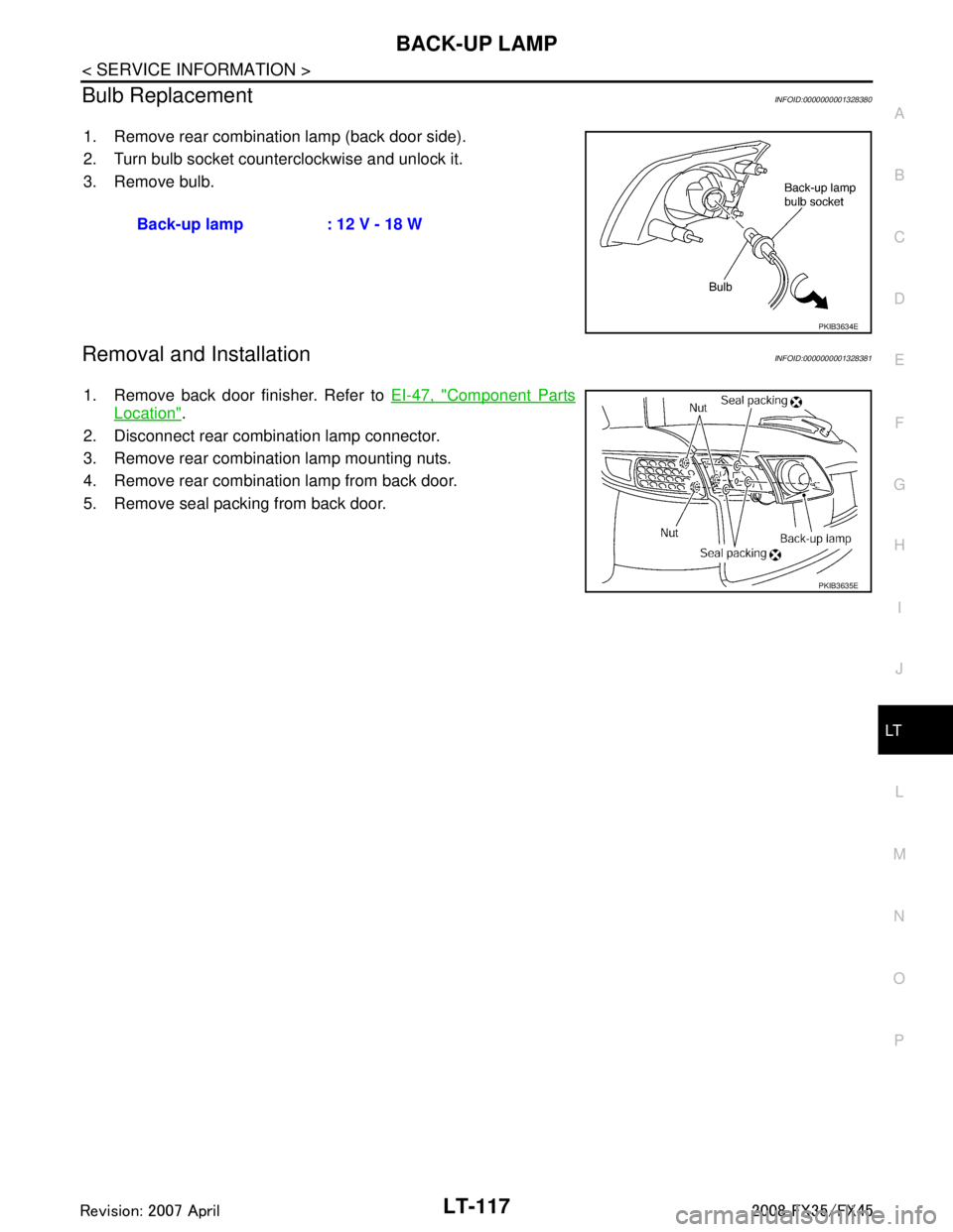
1. Remove rear combination lamp (back door side).
2. Turn bulb socket counterclockwise and unlock it.
3. Remove bulb.
Removal and InstallationINFOID:0000000001328381
1. Remove back door finisher. Refer to EI-47, "Component Parts
Location".
2. Disconnect rear combination lamp connector.
3. Remove rear combination lamp mounting nuts.
4. Remove rear combination lamp from back door.
5. Remove seal packing from back door. Back-up lamp : 12 V - 18 W
PKIB3634E
PKIB3635E
3AA93ABC3ACD3AC03ACA3AC03AC63AC53A913A773A893A873A873A8E3A773A983AC73AC93AC03AC3
3A893A873A873A8F3A773A9D3AAF3A8A3A8C3A863A9D3AAF3A8B3A8C
Page 3239 of 3924

REAR COMBINATION LAMPLT-137
< SERVICE INFORMATION >
C
DE
F
G H
I
J
L
M A
B
LT
N
O P
REAR COMBINATION LAMP
Bulb ReplacementINFOID:0000000001328404
REAR FENDER SIDE (REAR SIDE MARKER LAMP BULB)
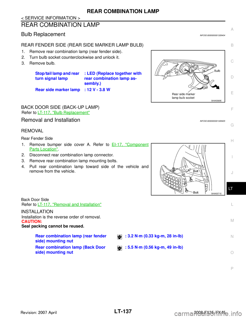
1. Remove rear combination lamp (rear fender side).
2. Turn bulb socket counterclockwise and unlock it.
3. Remove bulb.
BACK DOOR SIDE (BACK-UP LAMP)
Refer to LT-117, "Bulb Replacement"
Removal and InstallationINFOID:0000000001328405
REMOVAL
Rear Fender Side
1. Remove bumper side cover A. Refer to EI-17, "Component
Parts Location".
2. Disconnect rear combination lamp connector.
3. Remove rear combination lamp mounting bolts.
4. Pull rear combination lamp toward side of the vehicle and remove from the vehicle.
Back Door Side
Refer to LT-117, "Removal and Installation"
INSTALLATION
Installation is the reverse order of removal.
CAUTION:
Seal packing cannot be reused.Stop/tail lamp and rear
turn signal lamp
: LED (Replace together with
rear combination lamp as-
sembly.)
Rear side marker lamp : 12 V - 3.8 W
SKIA5569E
SKIA5571E
Rear combination lamp (rear fender
side) mounting nut : 3.2 N·m (0.33 kg-m, 28 in-lb)
Rear combination lamp (Back Door
side) mounting nut : 5.5 N·m (0.56 kg-m, 49 in-lb)
3AA93ABC3ACD3AC03ACA3AC03AC63AC53A913A773A893A873A873A8E3A773A983AC73AC93AC03AC3
3A893A873A873A8F3A773A9D3AAF3A8A3A8C3A863A9D3AAF3A8B3A8C
Page 3267 of 3924

INTERIOR ROOM LAMPLT-165
< SERVICE INFORMATION >
C
DE
F
G H
I
J
L
M A
B
LT
N
O P
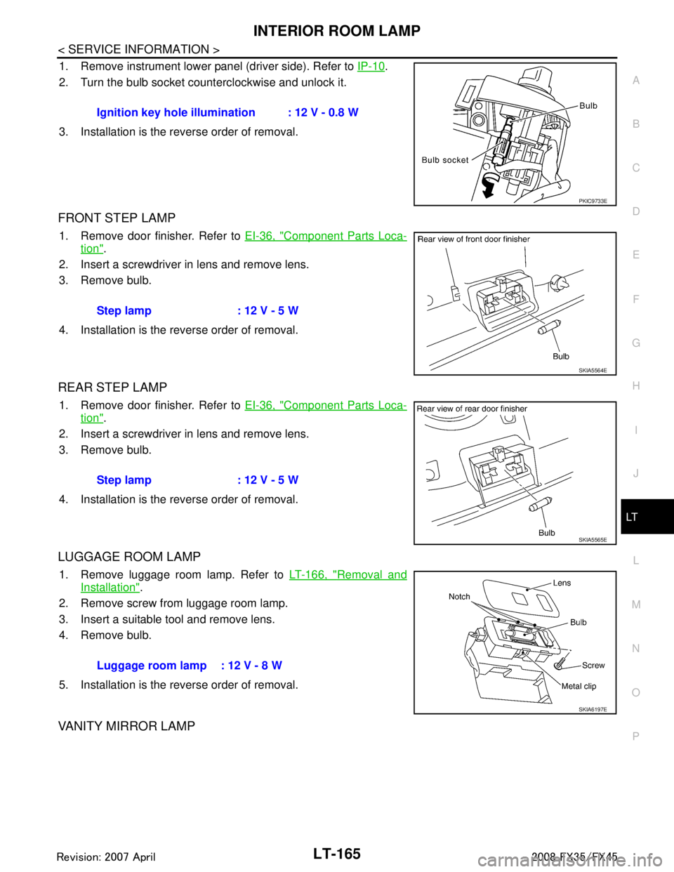
1. Remove instrument lower panel (driver side). Refer to IP-10.
2. Turn the bulb socket counterclockwise and unlock it.
3. Installation is the reverse order of removal.
FRONT STEP LAMP
1. Remove door finisher. Refer to EI-36, "Component Parts Loca-
tion".
2. Insert a screwdriver in lens and remove lens.
3. Remove bulb.
4. Installation is the reverse order of removal.
REAR STEP LAMP
1. Remove door finisher. Refer to EI-36, "Component Parts Loca-
tion".
2. Insert a screwdriver in lens and remove lens.
3. Remove bulb.
4. Installation is the reverse order of removal.
LUGGAGE ROOM LAMP
1. Remove luggage room lamp. Refer to LT-166, "Removal and
Installation".
2. Remove screw from luggage room lamp.
3. Insert a suitable tool and remove lens.
4. Remove bulb.
5. Installation is the reverse order of removal.
VANITY MIRROR LAMP
Ignition key hole illumination : 12 V - 0.8 W
PKIC9733E
Step lamp : 12 V - 5 W
SKIA5564E
Step lamp : 12 V - 5 W
SKIA5565E
Luggage room lamp : 12 V - 8 W
SKIA6197E
3AA93ABC3ACD3AC03ACA3AC03AC63AC53A913A773A893A873A873A8E3A773A983AC73AC93AC03AC3
3A893A873A873A8F3A773A9D3AAF3A8A3A8C3A863A9D3AAF3A8B3A8C
Page 3271 of 3924

ILLUMINATIONLT-169
< SERVICE INFORMATION >
C
DE
F
G H
I
J
L
M A
B
LT
N
O P
ILLUMINATION
System DescriptionINFOID:0000000001328422
Control of illumination lamps operation is dependent upon position of lighting switch (combination switch).
When lighting switch is placed in the 1ST or 2ND positi on (or if auto light system is activated), BCM (body con-
trol module) receives input signal requesting illuminati on lamps to illuminate. This input signal is communi-
cated to IPDM E/R (intelligent power distribution module engine room) through the CAN communication. The
CPU (central processing unit) located in the IPDM E/R co ntrols tail lamp relay coil. This relay, when energized,
directs power to illumination lamps, which then illuminate.
Power is supplied at all times
through 10A fuse (No. 71, located in IPDM E/R)
to tail lamp relay, located in IPDM E/R, and
to CPU located in IPDM E/R.
Power is also supplied at all times
through 50A fusible link (letter M, located in fuse, fusible link and relay box)
to BCM terminal 55,
through 15A fuse [No. 22 located in fuse block (J/B)]
to BCM terminal 42,
through 15A fuse (No. 78, located in IPDM E/R)
to CPU located in IPDM E/R,
through 10A fuse [No. 19 located in fuse block (J/B)]
to unified meter and A/C amp. terminal 21 and
to combination meter terminal 8.
With ignition switch in ON or START position, power is supplied
to ignition relay, located in IPDM E/R, from battery direct,
through 15A fuse [No. 1 located in fuse block (J/B)]
to BCM terminal 38,
through 10A fuse [No. 12, located in fuse block (J/B)]
to unified meter and A/C amp. terminal 22 and
to combination meter terminal 7.
With ignition switch in ACC or ON position, power is supplied
through 10A fuse [No. 6, located in fuse block (J/B)]
to combination meter terminal 4 and
to BCM terminal 11.
Ground is supplied
to BCM terminals 49 and 52
to unified meter and A/C amp. terminals 29 and 30, and
to combination meter terminals 5, 6, and 15
through grounds M35, M45, and M85,
to IPDM E/R terminals 38 and 60
through grounds E21, E50, and E51.
ILLUMINATION OPERATION BY LIGHTING SWITCH
With lighting switch in the 1ST or 2ND position (or if auto light system is activated), BCM receives input signal
requesting illumination lamps to illuminate. This input signal is communicated to IPDM E/R through the CAN
communication. The CPU located in the IPDM E/R controls tail lamp relay coil, which, when energized, directs
power
through IPDM E/R terminal 22
to glove box lamp terminal 1
to A/T device (illumination) terminal 11
to snow mode switch (illumination) terminal 5
to VDC off switch (illumination) terminal 3
to clock (illumination) terminal 3
to hazard switch (illumination) terminal 3
to heated seat switch (driver side) (illumination) terminal 5
to heated seat switch (passenger side) (illumination) terminal 5
to door mirror remote control switch (illumination) terminal 16
to LDW switch (illumination) terminal 5
to combination switch (spiral cable) terminal 26
to microphone terminal 2 (with telephone system)
3AA93ABC3ACD3AC03ACA3AC03AC63AC53A913A773A893A873A873A8E3A773A983AC73AC93AC03AC3
3A893A873A873A8F3A773A9D3AAF3A8A3A8C3A863A9D3AAF3A8B3A8C