headlamp INFINITI FX35 2008 Repair Manual
[x] Cancel search | Manufacturer: INFINITI, Model Year: 2008, Model line: FX35, Model: INFINITI FX35 2008Pages: 3924, PDF Size: 81.37 MB
Page 3128 of 3924

LT-26
< SERVICE INFORMATION >
HEADLAMP - XENON TYPE -
3. Check continuity between IPDM E/R harness connector E7 ter-minal 30 and front combination lamp LH harness connector E44
terminal 6.
OK or NG
OK >> Replace IPDM E/R. Refer to PG-24, "Removal and
Installation of IPDM E/R".
NG >> Repair harness or connector.
Headlamps Does Not Turn OFFINFOID:0000000001381748
1.CHECK HEADLAMP TURN OFF
Make sure that lighting switch is OFF. And check if headlamp turns off when ignition switch is turned OFF.
OK or NG
OK >> GO TO 3.
NG >> GO TO 2.
2.CHECK COMBINATION SWITCH INPUT SIGNAL
CONSULT-III DATA MONITOR
1. Select “HEAD LAMP1” and “HEAD LAMP2” of BCM data monitor item.
2. With operating the lighting switch, check the monitor status.
OK or NG
OK >> Replace IPDM E/R. Refer to PG-24, "Removal and Installation of IPDM E/R".
NG >> Check combination switch (lighting switch). Refer to LT-104, "
Combination Switch Inspection".
3.CHECKING CAN COMMUNICATIONS BETWEEN BCM AND IPDM E/R
Perform self-diagnosis for “BCM” with CONSULT-III.
Display of self-diagnosis results
NO DTC>> Replace IPDM E/R. Refer to PG-24, "Removal and Installation of IPDM E/R".
CAN COMM CIRCUIT>> Refer to LAN-43, "
CAN System Specification Chart".
General Information for Xenon Headlamp Trouble DiagnosisINFOID:0000000001328284
In most cases, malfunction of xenon headlamp - “does not ill uminate”, “flickers” or “dark” - is caused by a mal-
functioning xenon bulb. A malfunctioning HID control unit or lamp housing, however, may be a cause. Be sure
to perform trouble diagnosis following the steps described below.
Caution:INFOID:0000000001328285
Installation or removal of connector must be done with lighting switch OFF.
Disconnect the battery cable from the negative terminal or remove power fuse.
When the lamp is illuminated (when lighting switch is ON), never touch harness, HID control unit, inside of
lamp, or lamp metal parts.
To check illumination, temporarily install lamp in vehicle. Be sure to connect power at vehicle side connector.
If error can be traced directly to electrical system, fi rst check for items such as blown fuses and fusible links,
broken wires or loose connectors, dislocated terminals, and improper connections.
Never work with wet hands.
Using a tester for HID control unit circuit trouble diagnosis is prohibited.
Disassembling HID control unit or harnesses ( bulb socket harness, ECM harness) is prohibited.
Immediately after illumination, light intensity and color will fluctuate, but there is nothing wrong.
When bulb has come to end of its life, brightness will dr op significantly, it will flash repeatedly, or light color
will turn reddish. 30 – 6 : Continuity should exist.
PKIA5213E
When lighting switch is OFF : HEAD LAMP SW1 OFF
: HEAD LAMP SW2 OFF
3AA93ABC3ACD3AC03ACA3AC03AC63AC53A913A773A893A873A873A8E3A773A983AC73AC93AC03AC3
3A893A873A873A8F3A773A9D3AAF3A8A3A8C3A863A9D3AAF3A8B3A8C
Page 3129 of 3924

HEADLAMP - XENON TYPE -LT-27
< SERVICE INFORMATION >
C
DE
F
G H
I
J
L
M A
B
LT
N
O P
Xenon Headlamp Trouble DiagnosisINFOID:0000000001328286
1.CHECK 1: XENON HEADLAMP LIGHTING
Install normal xenon bulb to corresponding xenon bulb headlamp, and check if lamp lights up.
OK or NG
OK >> Replace xenon bulb.
NG >> GO TO 2.
2.CHECK 2: XENON HEADLAMP LIGHTING
Install normal HID control unit to corresponding xenon headlamp, and check if lamp lights up.
OK or NG
OK >> Replace HID control unit.
NG >> GO TO 3.
3.CHECK 3: XENON HEADLAMP LIGHTING
Install normal xenon lamp housing assembly to corresponding xenon headlamp, and check if lamp lights up.
OK or NG
OK >> Replace xenon headlamp housing assembly. [Malfunction in starter (boosting circuit) in xenon headlamp housing]
NG >> INSPECTION END
Aiming AdjustmentINFOID:0000000001328287
PREPARATION BEFORE ADJUSTING
For details, refer to the regulations in your own country.
Before performing aiming adjustment, check the following.
1. Keep all tires inflated to correct pressures.
2. Place vehicle on level ground.
3. Set that there is no-load in vehicle other than the driv er (or equivalent weight placed in driver's position).
Coolant, engine oil filled up to correct level and full fuel tank.
LOW BEAM AND HIGH BEAM
PKIC9684E
3AA93ABC3ACD3AC03ACA3AC03AC63AC53A913A773A893A873A873A8E3A773A983AC73AC93AC03AC3
3A893A873A873A8F3A773A9D3AAF3A8A3A8C3A863A9D3AAF3A8B3A8C
Page 3130 of 3924

LT-28
< SERVICE INFORMATION >
HEADLAMP - XENON TYPE -
1. Turn headlamp low beam ON.CAUTION:
Be sure aiming switch is set to “0” when performing aiming
adjustment.
2. Use adjusting screws to perform aiming adjustment.
ADJUSTMENT USING AN ADJUSTMENT SCREEN (LIGHT/DARK BORDERLINE)
If the vehicle front body has been repaired and/or headlamp assembly has been replaced, check aiming.
Use the aiming chart shown in the figure.
Basic illumination area for adjustment should be within the range shown on the aiming chart. Adjust headlamp accordingly.
Bulb ReplacementINFOID:0000000001328288
HEADLAMP HIGH/LOW BEAM
PKIB3650E
PKIC9731E
3AA93ABC3ACD3AC03ACA3AC03AC63AC53A913A773A893A873A873A8E3A773A983AC73AC93AC03AC3
3A893A873A873A8F3A773A9D3AAF3A8A3A8C3A863A9D3AAF3A8B3A8C
Page 3131 of 3924

HEADLAMP - XENON TYPE -LT-29
< SERVICE INFORMATION >
C
DE
F
G H
I
J
L
M A
B
LT
N
O P
1. Turn lighting switch OFF.
2. Disconnect the battery cable from the negative terminal or remove power fuse.
3. Remove air cleaner case (when replacing LH bulb). Refer to EM-173
(VK45) or refer to EM-17 (VQ35).
4. Remove radiator reservoir tank (when replacing RH bulb). Refer to CO-40
(VK45) or refer to CO-13 (VQ35).
5. Turn plastic cap counterclockwise and unlock it.
6. Turn bulb socket counterclockwise and unlock it.
7. Unlock retaining spring and remove bulb from headlamp.
8. Installation is the reverse order of removal. NOTE:
After installation, perform aiming adjustment. Refer to LT-27, "
Aiming Adjustment".
DAYTIME/PARKING LAMP
1. Turn lighting switch OFF.
2. Remove air cleaner case (when replacing LH bulb of VK45).
Refer to EM-173
.
3. Turn bulb socket counterclockwise and unlock it.
4. Remove bulb from its socket.
5. Installation is the reverse order of removal.
FRONT TURN SIGNAL LAMP
1. Turn lighting switch OFF.
2. Turn bulb socket counterclockwise with suitable tool and unlock it.
3. Remove bulb from its socket.
4. Installation is the reverse order of removal.
FRONT SIDE MARKER LAMP
1. Turn lighting switch OFF.
2. Turn bulb socket counterclockwise and unlock it.
3. Remove bulb from its socket.
4. Installation is the reverse order of removal.
CAUTION:Headlamp high/low beam (Xenon) : 12 V - 35 W (D2S)
PKIC9730E
Daytime/Parking lamp : 12 V - 21/5 W
PKIC9732E
Front turn signal lamp : 12 V - 21 W (amber)
SKIA6182E
Front side marker lamp : 12 V - 3.8 W
SKIA5552E
3AA93ABC3ACD3AC03ACA3AC03AC63AC53A913A773A893A873A873A8E3A773A983AC73AC93AC03AC3
3A893A873A873A8F3A773A9D3AAF3A8A3A8C3A863A9D3AAF3A8B3A8C
Page 3132 of 3924

LT-30
< SERVICE INFORMATION >
HEADLAMP - XENON TYPE -
After installing bulb, be sure to install plastic cap and bulb socket securely to insure watertight-
ness.
Removal and InstallationINFOID:0000000001328289
REMOVAL
1. Disconnect the battery cable from the negative terminal or remove power fuse.
2. Remove front bumper fascia assembly. Refer to EI-14, "
Compo-
nent Parts Location".
3. Remove headlamp mounting bolts and nut.
4. Remove plastics bumper bracket, then pull headlamp toward vehicle front, disconnect connector, and remove headlamp.
INSTALLATION
Installation is the reverse order of removal.
NOTE:
After installation, perform aiming adjustment. Refer to LT-27, "
Aiming Adjustment".
Disassembly and AssemblyINFOID:0000000001328290
DISASSEMBLY
1. Turn plastic cap counterclockwise and unlock it.
SKIA5553E
Headlamp mounting bolt : 6.1 N·m (0.62 kg-m, 54 in-lb)
1. Side marker lamp bulb 2. Side marker lamp bulb socket 3. Front turn signal lamp bulb socket
4. Front turn signal lamp bulb 5. Seal packing 6. Plastic cap
7. Xenon bulb (high/low) 8. Xenon bulb socket (high/low) 9. HID control unit cover mounting screw
10. HID control unit cover 11. HID control unit mounting screw 12. HID control unit
13. Seal packing 14. Daytime/Parking lamp bulb socket 15. Daytime/Parking lamp bulb
16. Headlamp housing assembly 17. Retaining spring
:Alway replace after every disassembly
:N·m (kg-m, in-lb)
PKIC9685E
3AA93ABC3ACD3AC03ACA3AC03AC63AC53A913A773A893A873A873A8E3A773A983AC73AC93AC03AC3
3A893A873A873A8F3A773A9D3AAF3A8A3A8C3A863A9D3AAF3A8B3A8C
Page 3133 of 3924

HEADLAMP - XENON TYPE -LT-31
< SERVICE INFORMATION >
C
DE
F
G H
I
J
L
M A
B
LT
N
O P
2. Turn xenon bulb socket count erclockwise, and unlock it.
3. Unlock retaining spring, and remove xenon bulb (high/low).
4. Remove HID control unit cover mounting screw.
5. Remove HID control unit cover.
6. Disconnect HID control unit connector.
7. Remove HID control unit mounting screws.
8. Remove HID control unit.
9. Turn daytime/parking lamp bulb socket counterclockwise and unlock it.
10. Remove daytime/parking lamp bulb from its socket.
11. Turn front turn signal lamp bulb socket counterclockwise and unlock it.
12. Remove front turn signal lamp bulb from its socket.
13. Turn front side marker lamp bulb socket counterclockwise and unlock it.
14. Remove front side marker lamp bulb from its socket.
ASSEMBLY
Assembly is the reverse order of disassembly.
CAUTION:
When HID control unit is removed, rein stall it securely and avoid any looseness.
After installing bulb, be sure to install plastic cap and bulb socket securely to insure watertightness.
HID control unit mounting screw
: 3.2 N·m (0.33 kg-m, 28 in-lb)
3AA93ABC3ACD3AC03ACA3AC03AC63AC53A913A773A893A873A873A8E3A773A983AC73AC93AC03AC3
3A893A873A873A8F3A773A9D3AAF3A8A3A8C3A863A9D3AAF3A8B3A8C
Page 3134 of 3924

LT-32
< SERVICE INFORMATION >
DAYTIME LIGHT SYSTEM
DAYTIME LIGHT SYSTEM
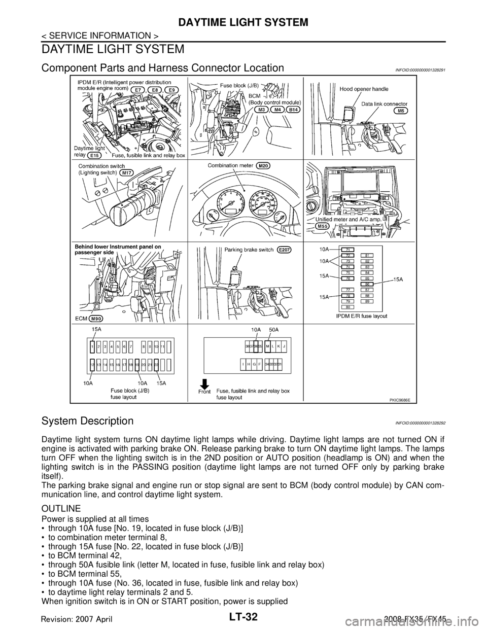
Component Parts and Harness Connector LocationINFOID:0000000001328291
System DescriptionINFOID:0000000001328292
Daytime light system turns ON daytime light lamps while driving. Daytime light lamps are not turned ON if
engine is activated with parking brake ON. Release parki ng brake to turn ON daytime light lamps. The lamps
turn OFF when the lighting switch is in the 2ND pos ition or AUTO position (headlamp is ON) and when the
lighting switch is in the PASSING position (daytime light lamps are not turned OFF only by parking brake
itself).
The parking brake signal and engine run or stop signal ar e sent to BCM (body control module) by CAN com-
munication line, and control daytime light system.
OUTLINE
Power is supplied at all times
through 10A fuse [No. 19, located in fuse block (J/B)]
to combination meter terminal 8,
through 15A fuse [No. 22, located in fuse block (J/B)]
to BCM terminal 42,
through 50A fusible link (letter M, located in fuse, fusible link and relay box)
to BCM terminal 55,
through 10A fuse (No. 36, located in fuse, fusible link and relay box)
to daytime light relay terminals 2 and 5.
When ignition switch is in ON or START position, power is supplied
PKIC9686E
3AA93ABC3ACD3AC03ACA3AC03AC63AC53A913A773A893A873A873A8E3A773A983AC73AC93AC03AC3
3A893A873A873A8F3A773A9D3AAF3A8A3A8C3A863A9D3AAF3A8B3A8C
Page 3145 of 3924

DAYTIME LIGHT SYSTEMLT-43
< SERVICE INFORMATION >
C
DE
F
G H
I
J
L
M A
B
LT
N
O P
1. Turn ignition switch OFF.
2. Disconnect combination meter connector.
3. Check continuity between combination meter harness connector M20 terminal 23 and parking brake switch harness connector
E207 terminal 1.
OK or NG
OK >> Replace combination meter.
NG >> Repair harness or connector.
CONSULT-III Functions (BCM)INFOID:0000000001328300
CONSULT-III can display each diagnostic item using the diagnostic test mode shown following.
CONSULT-III BASIC OPERATION
Refer to GI-34, "Description".
DATA MONITOR
Display Item List
1 – 23 : Continuity should exist.
SKIA5877E
BCM diagnosis part Diagnosis mode Description
HEADLAMP DATA MONITOR Displays BCM input data in real time.
ACTIVE TEST Operation of electrical loads can be checked by sending drive signal to them.
BCM SELF-DIAG RESULTS BCM performs self-diagnosis of CAN communication.
CAN DIAG SUPPORT MNTR The result of transmit/receive diagnosis of CAN communication can be read.
Monitor item Contents
IGN ON SW “ON/OFF” Displays “IGN position (ON)/OFF, ACC position (OFF)” judged from ignition switch sig-
nal.
ACC ON SW “ON/OFF” Displays “ACC (ON)/OFF, Ignition OFF (OFF)”
status judged from ignition switch sig-
nal.
HI BEAM SW “ON/OFF” Displays status (high beam switch: ON/Others: OFF) of high beam switch judged from
lighting switch signal.
HEAD LAMP SW 1 “ON/OFF” Displays status (headlamp switch 1: ON/Others: OFF) of headlamp switch 1 judged
from lighting switch signal.
HEAD LAMP SW 2 “ON/OFF” Displays status (headlamp switch 2: ON/Others: OFF) of headlamp switch 2 judged
from lighting switch signal.
LIGHT SW 1 ST “ON/OFF” Displays status (lighting switch 1ST or 2ND position: ON/Others: OFF) of lighting
switch judged from lighting switch signal.
AUTO LIGHT SW
NOTE 1 “ON/OFF” Displays status of lighting switch as judged from lighting switch signal. (AUTO position:
ON/Other than AUTO position: OFF)
PASSING SW “ON/OFF” Displays status (flash-to-pass switch: ON/Others: OFF) of flash-to-pass switch judged
from lighting switch signal.
FR FOG SW “ON/OFF” Displays status (front fog lamp switch: ON/Others: OFF) of front fog lamp switch
judged from lighting switch signal.
RR FOG SW
NOTE 3“OFF” —
DOOR SW - DR “ON/OFF” Displays status of driver door as judged from driver door switch signal. (Door is open:
ON/Door is closed: OFF)
DOOR SW - AS “ON/OFF” Displays status of passenger door as judged from passenger door switch signal. (Door
is open: ON/Door is closed: OFF)
DOOR SW - RR “ON/OFF” Displays status of rear door as judged from rear door switch (RH) signal. (Door is open:
ON/Door is closed: OFF)
3AA93ABC3ACD3AC03ACA3AC03AC63AC53A913A773A893A873A873A8E3A773A983AC73AC93AC03AC3
3A893A873A873A8F3A773A9D3AAF3A8A3A8C3A863A9D3AAF3A8B3A8C
Page 3146 of 3924

LT-44
< SERVICE INFORMATION >
DAYTIME LIGHT SYSTEM
NOTE:
1. Vehicles without auto light system display this item, but cannot be monitored.
2. Vehicles without daytime light system display this item, but cannot be monitored.
3. This item is displayed, but cannot be monitored.
ACTIVE TEST
Display Item List
NOTE:
1. Vehicles without daytime light lamp system display this item, but cannot be tested.
2. This item is displayed, but cannot be tested.
Daytime Light Control Does Not Operate ProperlyINFOID:0000000001328301
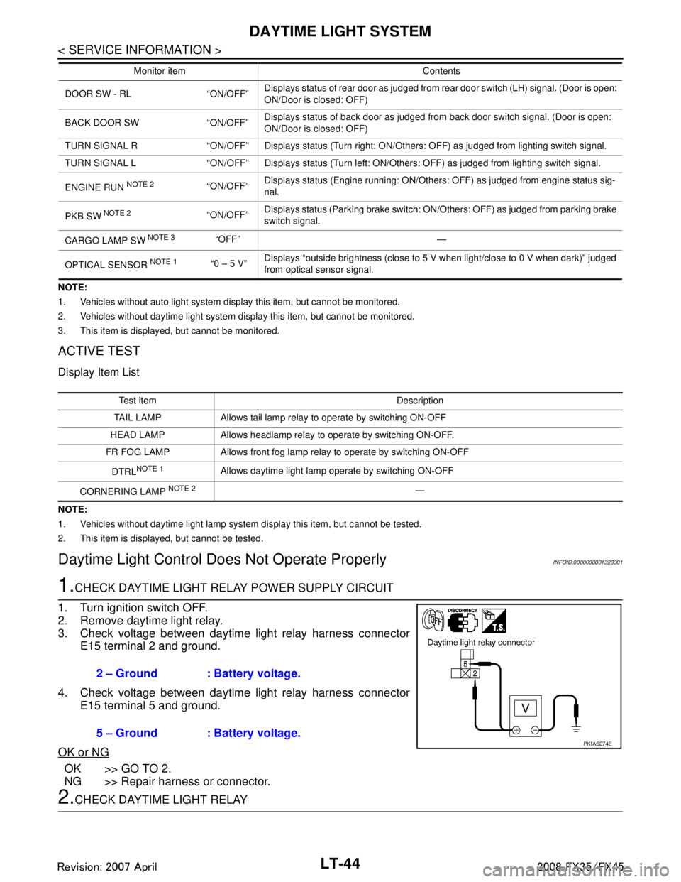
1.CHECK DAYTIME LIGHT RELAY POWER SUPPLY CIRCUIT
1. Turn ignition switch OFF.
2. Remove daytime light relay.
3. Check voltage between daytime light relay harness connector E15 terminal 2 and ground.
4. Check voltage between daytime light relay harness connector E15 terminal 5 and ground.
OK or NG
OK >> GO TO 2.
NG >> Repair harness or connector.
2.CHECK DAYTIME LIGHT RELAY
DOOR SW - RL “ON/OFF” Displays status of rear door as judged from rear door switch (LH) signal. (Door is open:
ON/Door is closed: OFF)
BACK DOOR SW “ON/OFF” Displays status of back door as judged from back door switch signal. (Door is open:
ON/Door is closed: OFF)
TURN SIGNAL R “ON/OFF” Displays status (Turn right: ON/Others: OFF) as judged from lighting switch signal.
TURN SIGNAL L “ON/OFF” Displays status (Turn left: ON/Others: OFF) as judged from lighting switch signal.
ENGINE RUN
NOTE 2“ON/OFF” Displays status (Engine running: ON/Others: OFF) as judged from engine status sig-
nal.
PKB SW
NOTE 2“ON/OFF” Displays status (Parking brake switch: ON/Others: OFF) as judged from parking brake
switch signal.
CARGO LAMP SW
NOTE 3 “OFF” —
OPTICAL SENSOR
NOTE 1 “0 – 5 V” Displays “outside brightness (close to 5 V when light/close to 0 V when dark)” judged
from optical sensor signal.
Monitor item Contents
Test item Description
TAIL LAMP Allows tail lamp relay to operate by switching ON-OFF
HEAD LAMP Allows headlamp relay to operate by switching ON-OFF.
FR FOG LAMP Allows front fog lamp relay to operate by switching ON-OFF
DTRL
NOTE 1Allows daytime light lamp operate by switching ON-OFF
CORNERING LAMP
NOTE 2—
2 – Ground : Battery voltage.
5 – Ground : Battery voltage.
PKIA5274E
3AA93ABC3ACD3AC03ACA3AC03AC63AC53A913A773A893A873A873A8E3A773A983AC73AC93AC03AC3
3A893A873A873A8F3A773A9D3AAF3A8A3A8C3A863A9D3AAF3A8B3A8C
Page 3149 of 3924

AUTO LIGHT SYSTEMLT-47
< SERVICE INFORMATION >
C
DE
F
G H
I
J
L
M A
B
LT
N
O P
AUTO LIGHT SYSTEM
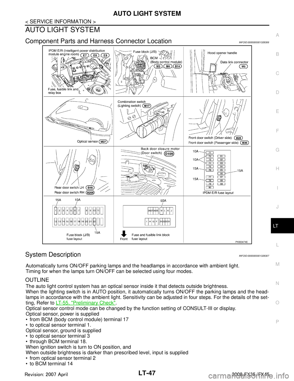
Component Parts and Har ness Connector LocationINFOID:0000000001328306
System DescriptionINFOID:0000000001328307
Automatically turns ON/OFF parking lamps and the headlamps in accordance with ambient light.
Timing for when the lamps turn ON/OFF can be selected using four modes.
OUTLINE
The auto light control system has an optical s ensor inside it that detects outside brightness.
When the lighting switch is in AUTO position, it automatically turns ON/OFF the parking lamps and the head-
lamps in accordance with the ambient li ght. Sensitivity can be adjusted in four steps. For the details of the set-
ting, Refer to LT-55, "
Preliminary Check".
Optical sensor control mode can be changed by the function setting of CONSULT-III or display.
Optical sensor, power is supplied
from BCM (body control module) terminal 17
to optical sensor terminal 1.
Optical sensor, ground is supplied
to optical sensor terminal 3
through BCM terminal 18.
When ignition switch is turn to ON position, and
When outside brightness is darker than prescribed level, input is supplied
from optical sensor terminal 2
to BCM terminal 14
PKIB3474E
3AA93ABC3ACD3AC03ACA3AC03AC63AC53A913A773A893A873A873A8E3A773A983AC73AC93AC03AC3
3A893A873A873A8F3A773A9D3AAF3A8A3A8C3A863A9D3AAF3A8B3A8C