lights INFINITI FX35 2008 Repair Manual
[x] Cancel search | Manufacturer: INFINITI, Model Year: 2008, Model line: FX35, Model: INFINITI FX35 2008Pages: 3924, PDF Size: 81.37 MB
Page 2893 of 3924

SERVICE INFORMATION FOR ELECTRICAL INCIDENTGI-31
< SERVICE INFORMATION >
C
DE
F
G H
I
J
K L
M B
GI
N
O P
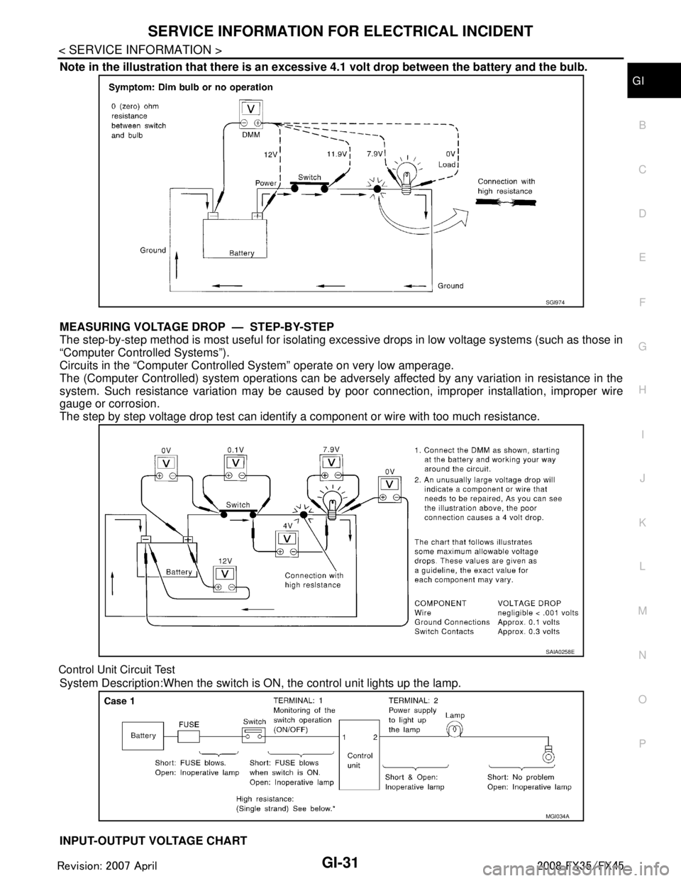
Note in the illustration that there is an excessi ve 4.1 volt drop between the battery and the bulb.
MEASURING VOLTAGE DRO P — STEP-BY-STEP
The step-by-step method is most useful for isolating ex cessive drops in low voltage systems (such as those in
“Computer Controlled Systems”).
Circuits in the “Computer Controlled System” operate on very low amperage.
The (Computer Controlled) system oper ations can be adversely affected by any variation in resistance in the
system. Such resistance variation may be caused by poor connection, improper installation, improper wire
gauge or corrosion.
The step by step voltage drop test can identify a component or wire with too much resistance.
Control Unit Circuit Test
System Description:When the switch is ON, the control unit lights up the lamp.
INPUT-OUTPUT VOLTAGE CHART
SGI974
SAIA0258E
MGI034A
3AA93ABC3ACD3AC03ACA3AC03AC63AC53A913A773A893A873A873A8E3A773A983AC73AC93AC03AC3
3A893A873A873A8F3A773A9D3AAF3A8A3A8C3A863A9D3AAF3A8B3A8C
Page 3120 of 3924

LT-18
< SERVICE INFORMATION >
HEADLAMP - XENON TYPE -
NOTE:
Perform monitoring of IPDM E/R data with ignition switch ON. When ignition switch is at ACC, display may not
be correct.
ACTIVE TEST
Headlamp Does Not Change To High Beam (Both Sides)INFOID:0000000001381742
1.CHECK COMBINATION SWITCH INPUT SIGNAL
CONSULT-III DATA MONITOR
1. Select “HI BEAM SW” of BCM data monitor item.
2. With operating the lighting switch, check the monitor status.
CHECK THE COMBINATION SWITCH
Refer to LT-104, "
Combination Switch Inspection".
OK or NG
OK >> GO TO 2.
NG >> Check combination switch (lighting switch). Refer to LT-104, "
Combination Switch Inspection".
2.HEADLAMP ACTIVE TEST
CONSULT-III ACTIVE TEST
1. Select “LAMPS” of IPDM E/R active test item.
2. With operating the test item, check the headlamp high beam operation.
IPDM E/R AUTO ACTIVE TEST
1. Start auto active test. Refer to PG-20, "
Auto Active Test".
2. Check that the headlamp high beam operation.
OK or NG
OK >> GO TO 3.
NG >> GO TO 4.
3.CHECK IPDM E/R
Item name CONSULT-III
screen display Display
or unit Monitor item selection
Description
ALL
SIGNALS MAIN
SIGNALS SELECTION
FROM MENU
Position lights request TAIL & CLR REQ ON/OFF ×× ×Signal status input from BCM
Headlamp low beam request HL LO REQ ON/OFF ×× ×Signal status input from BCM
Headlamp high beam request HL HI REQ ON/OFF ×× ×Signal status input from BCM
Front fog lights request FR FOG REQ ON/OFF ×× ×Signal status input from BCM
Te s t i t e mCONSULT-III
screen display Description
Headlamp relay (HI, LO) output
LAMPSAllows headlamp relay (HI, LO) to operate by switching operation (OFF, HI ON,
LO ON) at your option (Headlamp high beam repeats ON-OFF every 1 second).
Front fog lamp relay output Allows front fog lamp relay to operate by switching operation ON-OFF at your op-
tion.
Tail lamp relay output TAIL LAMP Allows tail lamp relay to operate by switching operation ON-OFF at your option.
When lighting switch is
HIGH BEAM : HI BEAM SW ON
Headlamp high beam should operate.
(Headlamp high beam repeats ON-OFF every 1 second).
Headlamp high beam should operate.
3AA93ABC3ACD3AC03ACA3AC03AC63AC53A913A773A893A873A873A8E3A773A983AC73AC93AC03AC3
3A893A873A873A8F3A773A9D3AAF3A8A3A8C3A863A9D3AAF3A8B3A8C
Page 3129 of 3924

HEADLAMP - XENON TYPE -LT-27
< SERVICE INFORMATION >
C
DE
F
G H
I
J
L
M A
B
LT
N
O P
Xenon Headlamp Trouble DiagnosisINFOID:0000000001328286
1.CHECK 1: XENON HEADLAMP LIGHTING
Install normal xenon bulb to corresponding xenon bulb headlamp, and check if lamp lights up.
OK or NG
OK >> Replace xenon bulb.
NG >> GO TO 2.
2.CHECK 2: XENON HEADLAMP LIGHTING
Install normal HID control unit to corresponding xenon headlamp, and check if lamp lights up.
OK or NG
OK >> Replace HID control unit.
NG >> GO TO 3.
3.CHECK 3: XENON HEADLAMP LIGHTING
Install normal xenon lamp housing assembly to corresponding xenon headlamp, and check if lamp lights up.
OK or NG
OK >> Replace xenon headlamp housing assembly. [Malfunction in starter (boosting circuit) in xenon headlamp housing]
NG >> INSPECTION END
Aiming AdjustmentINFOID:0000000001328287
PREPARATION BEFORE ADJUSTING
For details, refer to the regulations in your own country.
Before performing aiming adjustment, check the following.
1. Keep all tires inflated to correct pressures.
2. Place vehicle on level ground.
3. Set that there is no-load in vehicle other than the driv er (or equivalent weight placed in driver's position).
Coolant, engine oil filled up to correct level and full fuel tank.
LOW BEAM AND HIGH BEAM
PKIC9684E
3AA93ABC3ACD3AC03ACA3AC03AC63AC53A913A773A893A873A873A8E3A773A983AC73AC93AC03AC3
3A893A873A873A8F3A773A9D3AAF3A8A3A8C3A863A9D3AAF3A8B3A8C
Page 3144 of 3924

LT-42
< SERVICE INFORMATION >
DAYTIME LIGHT SYSTEM
OK >> GO TO 2.
NG >> If fuse is blown, be sure to eliminate cause of malfunction before installing new fuse. Refer to PG-
3.
2.CHECK POWER SUPPLY CIRCUIT
1. Turn ignition switch OFF.
2. Disconnect BCM connector.
3. Check voltage between BCM harness connector and ground.
OK or NG
OK >> GO TO 3.
NG >> Repair harness or connector.
3.CHECK GROUND CIRCUIT
Check continuity between BCM harness connector and ground.
OK or NG
OK >> INSPECTION END
NG >> Repair harness or connector.
INSPECTION PARKING BRAKE SWITCH CIRCUIT
1.CHECK BRAKE INDICATOR
1. Turn ignition switch ON.
2. When a parking brake is made ON/OFF, it checks w hether brake indicator lamp of combination meter
lights up / puts out the light.
OK or NG
OK >> INSPECTION END
NG >> GO TO 2.
2.CHECK PARKING BRAKE SWITCH SIGNAL
1. Turn ignition switch OFF.
2. Disconnect parking brake switch connector.
3. Turn ignition switch ON.
4. Check voltage between parking brake switch harness connector E207 terminal 1 and ground.
OK or NG
OK >> Replace parking brake switch.
NG >> GO TO 3.
3.CHECK PARKING BRAKE SWITCH CIRCUIT
(+) (-)Ignition switch position
BCM con- nector Te r m i n a l O F F O N
M3 38 GroundApprox. 0 V Battery voltage
M4 42 Battery voltage Battery voltage
55 Battery voltage Battery voltage
PKIA7520E
BCM connector Terminal
GroundContinuity
M4 49
Ye s
52
SKIA5294E
1 – Ground : Battery voltage.
SKIA5876E
3AA93ABC3ACD3AC03ACA3AC03AC63AC53A913A773A893A873A873A8E3A773A983AC73AC93AC03AC3
3A893A873A873A8F3A773A9D3AAF3A8A3A8C3A863A9D3AAF3A8B3A8C
Page 3150 of 3924

LT-48
< SERVICE INFORMATION >
AUTO LIGHT SYSTEM
The headlamps will then illuminate. For a description of headlamp operation, Refer to LT- 5 , "System Descrip-
tion".
COMBINATION SWITCH READING FUNCTION
Refer to BCS-4, "System Description".
DELAY TIMER FUNCTION
Delay timer function carries out a function that BCM ac tivates the timer and controls lights out of headlamps by
door switch signal and lightning switch signal when turn ing the Ignition switch OFF while it is ON and head-
lamps are ON by the auto light function.
Timer types are a 5 minute timer and a 45 second timer
When opening any door (door switch is ON), the 5 mi nute timer starts and then headlamps go out 5 minutes
later
When all the doors are closed (from door switch ON to OFF), the 45 second timer starts and then headlamps go out 45 seconds later. If any door is opened (door switch ON) while the 45 second timer is in operation, the
5 minute timer starts again
The timer stops when turning on the ignition switch or turning off the auto light switch under the above condi-
tions.
Delay timer control mode can be changed by the f unction setting of CONSULT-III or display.
CAN Communication System DescriptionINFOID:0000000001328308
CAN (Controller Area Network) is a serial communication line for real time application. It is an on-vehicle mul-
tiplex communication line with high data communication s peed and excellent error detection ability. Many elec-
tronic control units are equipped onto a vehicle, and each control unit shares information and links with other
control units during operation (not independent). In CA N communication, control units are connected with 2
communication lines (CAN H line, CAN L line) allowing a high rate of information transmission with less wiring.
Each control unit transmits/receives data but selectively reads required data only.
CAN Communication UnitINFOID:0000000001328309
Refer to LAN-43, "CAN System Specification Chart".
Major Component and FunctionsINFOID:0000000001328310
Components Functions
BCM Turns on/off circuits of tail light and headlamp according to signals from light sensor, lighting switch (AUTO),
driver door switch, passenger door switch, rear door switch, and ignition switch (ON, OFF).
Optical sensor Converts outside brightness (lux) to voltage, and sends it to BCM. (Detects brightness of 800 to 2,500 lux)
3AA93ABC3ACD3AC03ACA3AC03AC63AC53A913A773A893A873A873A8E3A773A983AC73AC93AC03AC3
3A893A873A873A8F3A773A9D3AAF3A8A3A8C3A863A9D3AAF3A8B3A8C
Page 3160 of 3924

LT-58
< SERVICE INFORMATION >
AUTO LIGHT SYSTEM
DATA MONITOR
All Signals, Main Signals, Selection From Menu
NOTE:
Perform monitoring of IPDM E/R data with ignition switch ON. When ignition switch is at ACC, the display may
not be correct.
ACTIVE TEST
Symptom ChartINFOID:0000000001328319
Lighting Switch InspectionINFOID:0000000001381749
1.CHECK LIGHTING SWITCH INPUT SIGNAL
CONSULT-III DATA MONITOR
1. Select “AUTO LIGHT SW” of BCM (HEAD LAMP) data monitor item.
2. With operating the lighting switch AUTO, check the monitor status.
CHECK THE COMBINATION SWITCH
Refer to LT-104, "
Combination Switch Inspection".
OK or NG
OK >> INSPECTION END
NG >> Check combination switch (lighting switch). Refer to LT-104, "
Combination Switch Inspection".
Item nameCONSULT-III
screen display Display
or unit Monitor item selection
Description
ALL
SIGNALS MAIN
SIGNALS SELECTION
FROM MENU
Position lights reques t TAIL & CLR REQ ON/OFF ×× ×Signal status input from BCM
Headlamp low beam request HL LO REQ ON/OFF ×× ×Signal status input from BCM
Headlamp high beam request HL HI REQ ON/OFF ×× ×Signal status input from BCM
Front fog lights request FR FOG REQ ON/OFF ×× ×Signal status input from BCM
Te s t i t e mCONSULT-III
screen display Description
Headlamp relay (HI, LO) output LAMPSAllows headlamp relay (HI, LO) to operate by switching operation (OFF, HI ON,
LO ON) at your option (Head lamp high beam repeats ON-OFF every 1 second).
Front fog lamp relay output Allows fog lamp relay to operate by switching operation ON-OFF at your option.
Tail lamp relay output TAIL LAMP Allows tail lamp relay to operate by switching operation ON-OFF at your option.
Trouble phenomenon Malfunction system and reference
Parking, license plate, side marker and tail lamps and head- lamps will not illuminate when outside of the vehicle be-
comes dark. (Lighting switch 1ST position and 2ND position
operate normally.)
Parking, license plate, side marker and tail lamps and head-
lamp will not go out when outside of the vehicle becomes
light. (Lighting switch 1ST position and 2nd position operate
normally.)
Headlamps go out when outside of the vehicle becomes light, but parking lamps stay on. Refer to
LT- 5 6 , "
CONSULT-III Functions (BCM)".
Refer to LT- 5 8 , "
Lighting Switch Inspection".
Refer to LT- 5 9 , "
Optical sensor System Inspection".
If above systems are normal, replace BCM.
Shut off delay feature will not operate. CAN communication line inspection between BCM and combination
meter. Refer to PG-24, "
U1000 CAN COMM CIRCUIT".
Refer to BL-38, "
Check Door Switch".
If above system is normal, replace BCM.
When lighting switch is AUTO
position : AUTO LIGHT SW ON
3AA93ABC3ACD3AC03ACA3AC03AC63AC53A913A773A893A873A873A8E3A773A983AC73AC93AC03AC3
3A893A873A873A8F3A773A9D3AAF3A8A3A8C3A863A9D3AAF3A8B3A8C
Page 3766 of 3924

TROUBLE DIAGNOSISSRS-29
< SERVICE INFORMATION >
C
DE
F
G
I
J
K L
M A
B
SRS
N
O P
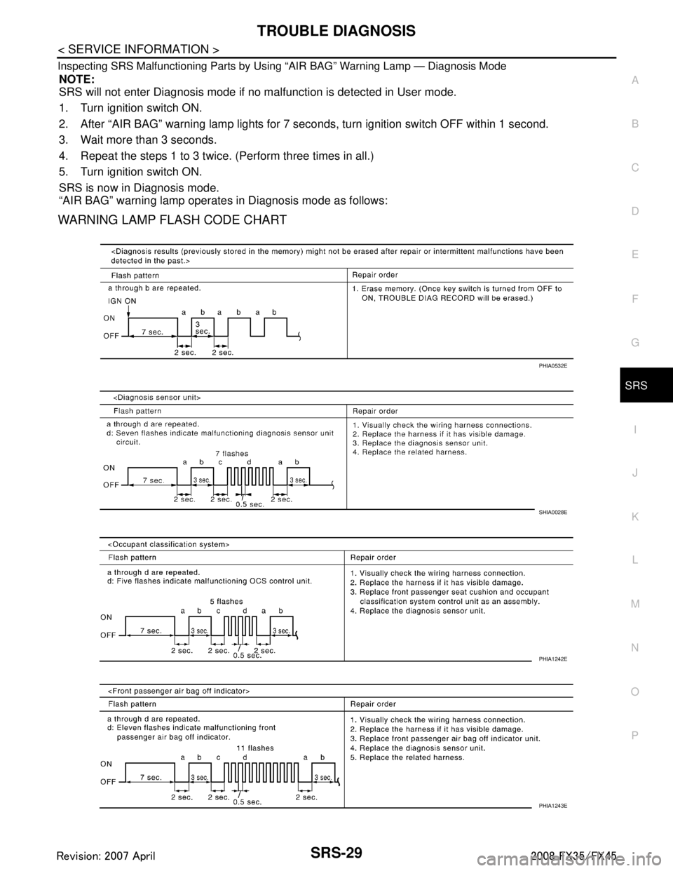
Inspecting SRS Malfunctioning Parts by Using “AIR BAG” Warning Lamp — Diagnosis Mode
NOTE:
SRS will not enter Diagnosis mode if no malfunction is detected in User mode.
1. Turn ignition switch ON.
2. After “AIR BAG” warning lamp lights for 7 seconds, turn ignition switch OFF within 1 second.
3. Wait more than 3 seconds.
4. Repeat the steps 1 to 3 twice. (Perform three times in all.)
5. Turn ignition switch ON.
SRS is now in Diagnosis mode.
“AIR BAG” warning lamp operates in Diagnosis mode as follows:
WARNING LAMP FLASH CODE CHART
PHIA0532E
SHIA0028E
PHIA1242E
PHIA1243E
3AA93ABC3ACD3AC03ACA3AC03AC63AC53A913A773A893A873A873A8E3A773A983AC73AC93AC03AC3
3A893A873A873A8F3A773A9D3AAF3A8A3A8C3A863A9D3AAF3A8B3A8C