Lighting System INFINITI FX35 2008 Service Manual
[x] Cancel search | Manufacturer: INFINITI, Model Year: 2008, Model line: FX35, Model: INFINITI FX35 2008Pages: 3924, PDF Size: 81.37 MB
Page 1 of 3924

ABCDEFGHIJKLQUICK REFERENCE INDEX AGENERAL INFORMATIONGIGeneral InformationBENGINEEMEngine MechanicalLUEngine Lubrication SystemCOEngine Cooling SystemECEngine Control SystemFLFuel SystemEXExhaust SystemACCAccelerator Control SystemCTRANSMISSION/
TRANSAXLEATAutomatic TransmissionDDRIVELINE/AXLETFTransferPRPropeller ShaftFFDFront Final DriveRFDRear Final DriveFAXFront AxleRAXRear AxleESUSPENSIONFSUFront SuspensionRSURear SuspensionWTRoad Wheels & TiresFBRAKESBRBrake SystemPBParking Brake SystemBRCBrake Control SystemGSTEERINGPSPower Steering SystemHRESTRAINTSSBSeat BeltsSRSSupplemental Restraint System
(SRS)IBODYBLBody, Lock & Security SystemGWGlasses, Window System & Mir-
rorsRFRoofEIExterior & InteriorIPInstrument PanelSESeatJAIR CONDITIONERATCAutomatic Air ConditionerKELECTRICALSCStarting & Charging SystemLTLighting SystemDIDriver Information SystemWWWiper, Washer & HornBCSBody Control SystemLANLAN SystemAVAudio Visual, Navigation & Tele-
phone SystemACSAuto Cruise Control SystemPGPower Supply, Ground & Circuit Ele-
mentsLMAINTENANCEMAMaintenanceEdition: April 2007
Revision: April 2007
Page 614 of 3924

INTEGRATED DISPLAY SYSTEMAV-67
< SERVICE INFORMATION >
C
DE
F
G H
I
J
L
M A
B
AV
N
O P
Terminal and Reference Valu e for Display Control UnitINFOID:0000000001328718
Te r m i n a l
(Wire color) ItemSignal
input/
output Condition
Reference value
+– Ignition
switch Operation
1 (W/L) Ground Battery power su pply Input OFF — Battery voltage
2 (W/G) Ground Power supply (Invert-
er)
Output ON — Approx. 9 V
3 (B) Ground Ground — ON — Approx. 0 V
4 (BR/W) Ground Power supply (Signal) Output ON — Approx. 9 V 5 (P) Ground Ground (Inverter) — ON — Approx. 0 V
6 (OR) Ground Reverse signal Input ON Selector lever in R position Approx. 12 V
Selector lever except in R
position
Approx. 0 V
7 (P/L) Ground Ground (Signal) — ON — Approx. 0 V
10 (LG) Ground ACC power supply Input ACC — Battery voltage 12 (W) Ground Ignition signal Input ON — Battery voltage13 (B) Ground Ground — ON — Approx. 0 V
14 (R/L) Ground Illumination signal Input OFF Lighting switch ON Approx. 12 V
Lighting switch OFF Approx. 0 V
16 (G) Ground Vehicle speed signal
(8-pulse) Input ONWhen vehicle speed is ap-
prox. 25 MPH (40 km/h) NOTE:
Maximum voltage may be 5 V
due to specifications (connected
units).
25 (L) — CAN-H — — — —
26 (P) — CAN-L — — — —
28 (PU) Ground Communication
signal (+) Input/
Output ON —
29 — Shield — — — —
30 (LG) Ground Communication
signal (–) Input/
Output ON —
PKIA1935E
SKIB7378E
SKIB7379E
3AA93ABC3ACD3AC03ACA3AC03AC63AC53A913A773A893A873A873A8E3A773A983AC73AC93AC03AC3
3A893A873A873A8F3A773A9D3AAF3A8A3A8C3A863A9D3AAF3A8B3A8C
Page 624 of 3924

INTEGRATED DISPLAY SYSTEMAV-77
< SERVICE INFORMATION >
C
DE
F
G H
I
J
L
M A
B
AV
N
O P
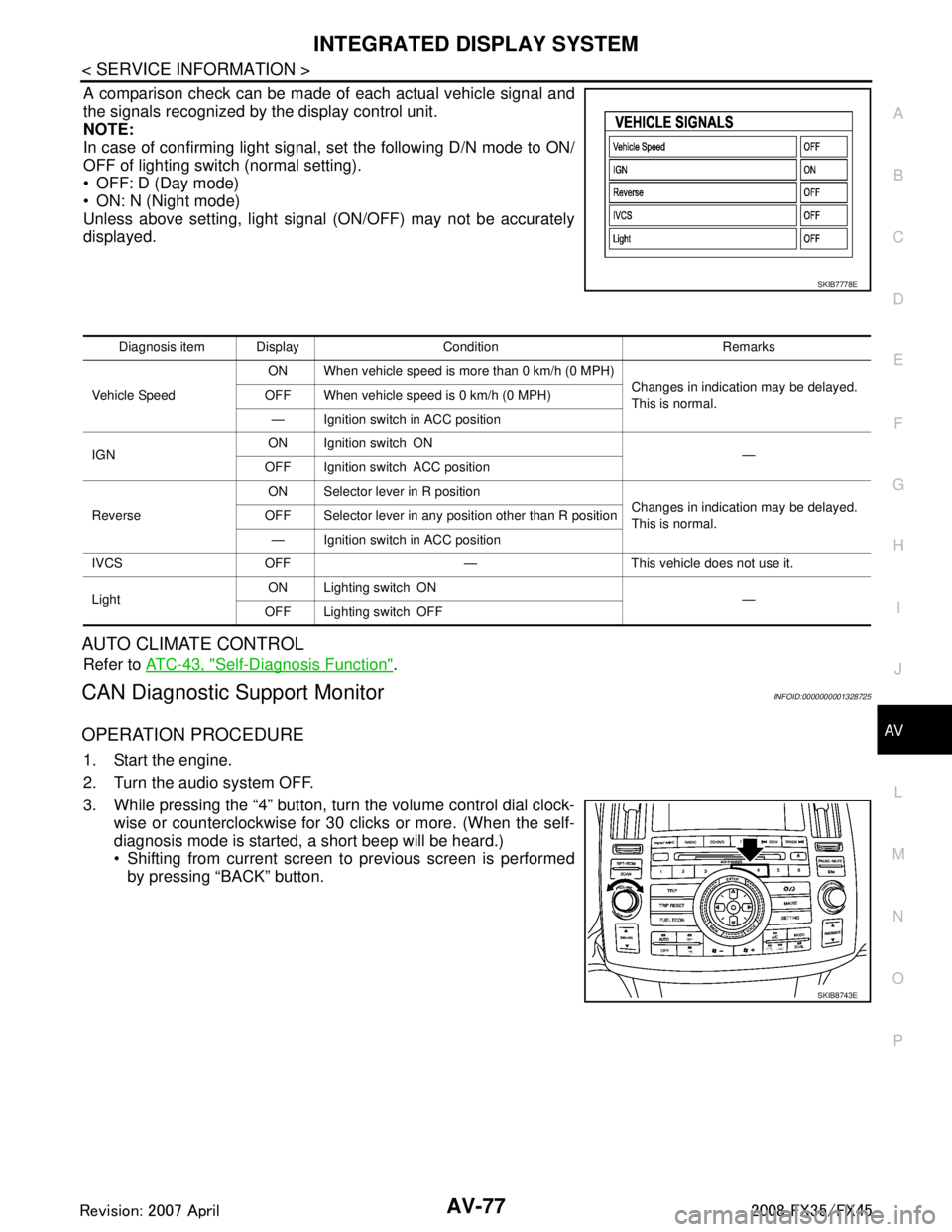
A comparison check can be made of each actual vehicle signal and
the signals recognized by the display control unit.
NOTE:
In case of confirming light signal, set the following D/N mode to ON/
OFF of lighting switch (normal setting).
OFF: D (Day mode)
ON: N (Night mode)
Unless above setting, light signal (ON/OFF) may not be accurately
displayed.
AUTO CLIMATE CONTROL
Refer to ATC-43, "Self-Diagnosis Function".
CAN Diagnostic Support MonitorINFOID:0000000001328725
OPERATION PROCEDURE
1. Start the engine.
2. Turn the audio system OFF.
3. While pressing the “4” button, turn the volume control dial clock-
wise or counterclockwise for 30 clicks or more. (When the self-
diagnosis mode is started, a short beep will be heard.)
Shifting from current screen to previous screen is performedby pressing “BACK” button.
SKIB7778E
Diagnosis item Display Condition Remarks
Vehicle Speed ON When vehicle speed is more than 0 km/h (0 MPH)
Changes in indication may be delayed.
This is normal.
OFF When vehicle speed is 0 km/h (0 MPH)
— Ignition switch in ACC position
IGN ON Ignition switch ON
—
OFF Ignition switch ACC position
Reverse ON Selector lever in R position
Changes in indication may be delayed.
This is normal.
OFF Selector lever in any position other than R position
— Ignition switch in ACC position
IVCS OFF — This vehicle does not use it.
Light ON Lighting switch ON
—
OFF Lighting switch OFF
SKIB8743E
3AA93ABC3ACD3AC03ACA3AC03AC63AC53A913A773A893A873A873A8E3A773A983AC73AC93AC03AC3
3A893A873A873A8F3A773A9D3AAF3A8A3A8C3A863A9D3AAF3A8B3A8C
Page 653 of 3924

AV-106
< SERVICE INFORMATION >
NAVIGATION SYSTEM
Terminal and Reference Va lue for NAVI Control Unit
INFOID:0000000001328747
Te r m i n a l
(Wire color) ItemSignal
input/
output Condition
Reference value
+– Ignition
switch Operation
1 (B) Ground Ground — ON — Approx. 0 V
2 (Y) Ground Battery power supply Input OFF — Battery voltage
5 (LG) Ground ACC power supply Input ACC — Battery voltage
12 (LG) 14 (PU) Voice guidance signal Output ON Press “GUIDE/VOICE”
button
13 — Shield — — — —
35 (B) Ground Ground — ON — Approx. 0 V
44 (R) Ground RGB sign al (R: red) Output ON Start Confirmation/Adjust-
ment (Navigation) mode,
and then display color bar by
selecting “Color Spectrum
bar” on Display Diagnosis
screen
45 (W) Ground RGB signal (G: green) Output ON Start Confirmation/Adjust-
ment (Navigation) mode,
and then display color bar by
selecting “Color Spectrum
bar” on Display Diagnosis
screen
46 (B) Ground RGB signal (B: blue) Output ON Start Confirmation/Adjust-
ment (Navigation) mode,
and then display color bar by
selecting “Color Spectrum
bar” on Display Diagnosis
screen
47 — Shield — — — —
48 (G) Ground RGB synchronizing
signal
Output ONWhen displaying RGB im-
age
49 — Shield — — — —
61 (R) Ground Illumination signal Input OFF Lighting switch ON Approx. 12 V
Lighting switch OFF Approx. 0 V
SKIB3609E
SKIB7360E
SKIB7361E
SKIB7362E
SKIB3603E
3AA93ABC3ACD3AC03ACA3AC03AC63AC53A913A773A893A873A873A8E3A773A983AC73AC93AC03AC3
3A893A873A873A8F3A773A9D3AAF3A8A3A8C3A863A9D3AAF3A8B3A8C
Page 655 of 3924

A V -108
< SERVICE INFORMATION >
NAVIGATION SYSTEM
10 (LG) Ground ACC power supply Input ACC — Battery voltage12 (W) Ground Ignition signal Input ON — Battery voltage13 (B) Ground Ground — ON — Approx. 0 V
14 (R/L) Ground Illumination signal Input OFF Lighting switch ON Approx. 12 V
Lighting switch OFF Approx. 0 V
16 (G) Ground Vehicle speed signal
(8-pulse) Input ON
When vehicle speed is ap-
prox. 25 MPH (40 km/h) NOTE:
Maximum voltage may be 5 V
due to specifications (connected
units).
25 (L) — CAN-H — — — —
26 (P) — CAN-L — — — —
28 (PU) Ground Communication
signal (+) Input/
Output ON —
29 — Shield — — — —
30 (LG) Ground Communication
signal (–) Input/
Output ON —
32 (L) Ground Communication
signal (+) Input/
Output ON —
33 — Shield — — — —
34 (P) Ground Communication
signal (–) Input/
Output ON —
Te r m i n a l
(Wire color) ItemSignal
input/
output Condition
Reference value
+– Ignition
switch Operation
PKIA1935E
SKIB7378E
SKIB7379E
SKIB7378E
SKIB7379E
3AA93ABC3ACD3AC03ACA3AC03AC63AC53A913A773A893A873A873A8E3A773A983AC73AC93AC03AC3
3A893A873A873A8F3A773A9D3AAF3A8A3A8C3A863A9D3AAF3A8B3A8C
Page 668 of 3924

NAVIGATION SYSTEMAV-121
< SERVICE INFORMATION >
C
DE
F
G H
I
J
L
M A
B
AV
N
O P
VEHICLE SIGNALS
A comparison check can be made of each actual vehicle signal and
the signals recognized by the display control unit.
NOTE:
In case of confirming light signal, set the following D/N mode to ON/
OFF of lighting switch (normal setting).
OFF: D (Day mode)
ON: N (Night mode)
Unless above setting, light signal (ON/OFF) may not be accurately
displayed.
AUTO CLIMATE CONTROL
Refer to ATC-43, "Self-Diagnosis Function".
NAVIGATION
Each diagnosis is shown by selecting each screen switch on Confir-
mation/Adjustment screen.
Display Diagnosis
R (red) signal error : Light blue (Cyan) tint
G (green) signal error : Purple (Magenta) tint
B (blue) signal error : Yellow tint
SKIB7778E
Diagnosis item Display Condition Remarks
Vehicle Speed ON When vehicle speed is more than 0 km/h (0 MPH)
Changes in indication may be delayed.
This is normal.
OFF When vehicle speed is 0 km/h (0 MPH)
— Ignition switch in ACC position
IGN ON Ignition switch ON
—
OFF Ignition switch ACC position
Reverse ON Selector lever in R position
Changes in indication may be delayed.
This is normal.
OFF Selector lever in any position other than R position
— Ignition switch in ACC position
IVCS OFF — This vehicle does not use it.
Light ON Lighting switch ON
—
OFF Lighting switch OFF
SKIB7386E
3AA93ABC3ACD3AC03ACA3AC03AC63AC53A913A773A893A873A873A8E3A773A983AC73AC93AC03AC3
3A893A873A873A8F3A773A9D3AAF3A8A3A8C3A863A9D3AAF3A8B3A8C
Page 669 of 3924

AV-122
< SERVICE INFORMATION >
NAVIGATION SYSTEM
Color tone and shading of the NAVI control unit-generated image can be checked by the display of a color bar
and a gray scale.
If RGB signal is malfunctioning, the tint of the color bar display is as follows.
Vehicle Signals
A comparison check can be made of each actual vehicle signal and
the signals recognized by the NAVI control unit.
Navigation
Steering Angle AdjustmentR (red) signal error : Light blue (Cyan) tint
G (green) signal error :
Purple (Magenta) tint
B (blue) signal error : Yellow tint
SKIB6976E
SKIB6977E
Diagnosis item Display Condition Remarks
Vehicle speed ON When vehicle speed is more than 0 km/h (0 MPH)
Changes in indication may be delayed.
This is normal.
OFF When vehicle speed is 0 km/h (0 MPH)
— Ignition switch in ACC position
Lights ON Lighting switch ON
—
OFF Lighting switch OFF
Ignition ON Ignition switch ON
—
OFF Ignition switch ACC position
Reverse ON Selector lever in R position
Changes in indication may be delayed.
This is normal.
OFF Selector lever in any position other than R position
— Ignition switch in ACC position
3AA93ABC3ACD3AC03ACA3AC03AC63AC53A913A773A893A873A873A8E3A773A983AC73AC93AC03AC3
3A893A873A873A8F3A773A9D3AAF3A8A3A8C3A863A9D3AAF3A8B3A8C
Page 713 of 3924

AV-166
< SERVICE INFORMATION >
TELEPHONE
Terminal and Reference Va lue for TEL Adapter Unit
INFOID:0000000001328793
Te r m i n a l
(Wire color) ItemSignal
input/
output Condition
Reference value
+– Ignition
switch Operation
1 (W/L) Ground Battery power supply Input OFF — Battery voltage 2 (LG) Ground ACC power supply Input ACC — Battery voltage3 (W) Ground Ignition signal Input ON — Battery voltage4 (B) Ground Ground — ON — Approx. 0 V 6—Shield —— — —
7 (R) 8 (B) MIC. signal Input ON Uttering in front of the micro-
phone while using the
hands-free phone system.
9 (P) 10 (L) TEL voice signal Output ON Receiving the party's voice
while using the hands-free
phone system.
11 (L/W) Ground TEL ON signal Output ON While using handsfree
phone system.
Approx. 0 V
While not using handsfree
phone system. Approx. 5 V
12 (LG) Ground Remote control A Input ON Press switch
Approx. 0 V
Press SEEK UP switch Approx. 1.7 V
Press VOL UP switch Approx. 3.3 V
Except for above Approx. 5 V
13 (GY) Ground Remote control B Input ON Press switch
Approx. 0 V
Press SEEK DOWN switch Approx. 1.7 V
Press VOL DOWN switch Approx. 3.3 V
Except for above Approx. 5 V
14 (SB) Ground Remote control
ground — ON — Approx. 0 V
15 (PU) Ground Indicator signal Output ON Microphone indicator ON,
and lighting switch OFF
Approx. 1.3 V
Microphone indicator ON,
and lighting switch ON Approx. 0.8 V
Microphone unit indicator
OFF Approx. 12 V
PKIB5037J
SKIB3609E
3AA93ABC3ACD3AC03ACA3AC03AC63AC53A913A773A893A873A873A8E3A773A983AC73AC93AC03AC3
3A893A873A873A8F3A773A9D3AAF3A8A3A8C3A863A9D3AAF3A8B3A8C
Page 724 of 3924

BCS-4
< SERVICE INFORMATION >
BCM (BODY CONTROL MODULE)
BCM (BODY CONTROL MODULE)
System DescriptionINFOID:0000000001328608
BCM (Body Control Module) controls the operation of various electrical units installed on the vehicle.
BCM FUNCTION
BCM has combination switch reading function for reading the operation of combination switches (light, wiper,
washer and turn signal) in addition to a function for cont rolling the operation of various electrical components.
Also it has an interface function allowing it to receive signals from the unified meter and A/C amp., and send
signals to ECM using CAN communication.
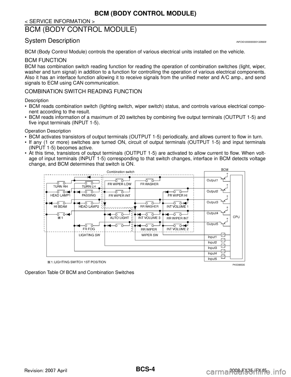
COMBINATION SWITCH READING FUNCTION
Description
BCM reads combination switch (lighting switch, wiper switch) status, and controls various electrical compo-
nent according to the result.
BCM reads information of a maximum of 20 switches by combining five output terminals (OUTPUT 1-5) and
five input terminals (INPUT 1-5).
Operation Description
BCM activates transistors of output terminals (OUTPUT 1-5) periodically, and allows current to flow in turn.
If any (1 or more) switches are turned ON, circui t of output terminals (OUTPUT 1-5) and input terminals
(INPUT 1-5) becomes active.
At this time, transistors of output terminals (OUTPUT 1- 5) are activated to allow current to flow. When volt-
age of input terminals (INPUT 1-5) corresponding to t hat switch changes, interface in BCM detects voltage
change, and BCM determines that switch is ON.
Operation Table Of BCM and Combination Switches
PKID0853E
3AA93ABC3ACD3AC03ACA3AC03AC63AC53A913A773A893A873A873A8E3A773A983AC73AC93AC03AC3
3A893A873A873A8F3A773A9D3AAF3A8A3A8C3A863A9D3AAF3A8B3A8C
Page 725 of 3924

BCM (BODY CONTROL MODULE)BCS-5
< SERVICE INFORMATION >
C
DE
F
G H
I
J
L
M A
B
BCS
N
O P
BCM reads operation status of combination swit ch using combinations shown in table below.
NOTE:
Headlamp system has a dual switch.
Sample Operation: (When Lighting Switch 1ST Position Turned ON)
When lighting switch 1ST position is turned ON, contact in combination switch turns ON. At this time if OUT-
PUT 4 transistor is activated, BCM detects that voltage changes in INPUT 5.
When OUTPUT 4 transistor is ON, BCM detects that voltage changes in INPUT 5, and judges that lighting
switch 1ST position is ON. Then BCM sends tail lamp and clearance lamp request signal to IPDM E/R using
CAN communication.
When OUTPUT 4 transistor is activated again, BCM detects that voltage changes in INPUT 5, and recog-
nizes that lighting switch 1S T position is continuously ON.
NOTE:
Each OUTPUT terminal transistor is activated at 10 ms intervals. Therefore after switch is turned ON, electri-
cal loads are activated with time delay. But this time delay is so short that it cannot be detected by human
senses.
Operation Mode
Combination switch reading function has operation modes shown below.
1. Normal status When BCM is not in sleep status, OUTPUT terminals (1-5) send out ON signal every 10 ms.
2. Sleep status
SKIA4959E
PKID0854E
3AA93ABC3ACD3AC03ACA3AC03AC63AC53A913A773A893A873A873A8E3A773A983AC73AC93AC03AC3
3A893A873A873A8F3A773A9D3AAF3A8A3A8C3A863A9D3AAF3A8B3A8C