heater INFINITI M35 2006 Factory User Guide
[x] Cancel search | Manufacturer: INFINITI, Model Year: 2006, Model line: M35, Model: INFINITI M35 2006Pages: 5621, PDF Size: 65.56 MB
Page 585 of 5621

4. Foot duct (left) 5. Ventilator")
ATC-138
HEATER & COOLING UNIT ASSEMBLY
Revision: 2006 January2006 M35/M45
Disassembly and AssemblyNJS000HG
1. Aspirator 2. Aspirator hose 3. Front heater duct (left)
4. Foot duct (left) 5. Ventilator door (left) 6. Ventilator door (right)
7. Foot duct (right) 8. Main link sub (right) 9. Ventilator door lever (right)
10. Ventilator door link (right) 11. Main link (right) 12. Mode door motor (passenger side)
13. Max. cool door link (right) 14. Air mix door motor (passenger side) 15. Intake sensor
16. Intake sensor bracket 17. Low-pressure pipe 1 18. High-pressure pipe 2
19. Expansion valve 20. Cooler pipe grommet 21. Insulator
22. Evaporator cover adapter 23. Air mix door (Slide door) 24. Clip
25. Heater & cooling unit case (left) 26. Heater pipe grommet 27. Heater core
28. Upper ventilator door motor 29. Air mix door motor (driver side) 30. Mode door motor (driver side)
31. Main link (left) 32. Main link sub (left) 33. Ventilator door lever (left)
34. Center case 35. Max. cool door lever (right) 36. Evaporator cover
RJIA4122E
Page 586 of 5621
 39. Upper ventilator door
40. Heater pipe c")
HEATER & COOLING UNIT ASSEMBLY
ATC-139
C
D
E
F
G
H
I
K
L
MA
B
AT C
Revision: 2006 January2006 M35/M45
37. Evaporator 38. Heater & cooling unit case (right) 39. Upper ventilator door
40. Heater pipe cover 41. Upper ventilator door rod 42. Upper ventilator door lever
43. Defroster door link 44. Ventilator door link (left) 45. Max. cool door lever (left)
46. Max. cool door (left) 47. Max. cool door (right) 48. Defroster door (right)
49. Defroster door (left) 50. Max. cool door link (left) 51. Defroster door lever
Page 587 of 5621
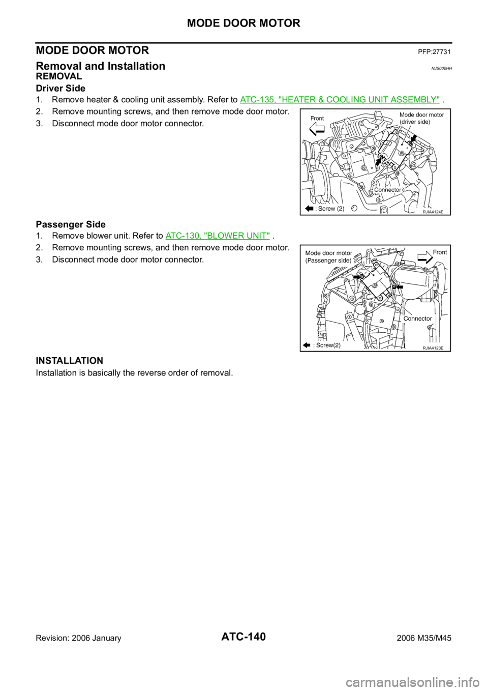
ATC-140
MODE DOOR MOTOR
Revision: 2006 January2006 M35/M45
MODE DOOR MOTORPFP:27731
Removal and InstallationNJS000HH
REMOVAL
Driver Side
1. Remove heater & cooling unit assembly. Refer to ATC-135, "HEATER & COOLING UNIT ASSEMBLY" .
2. Remove mounting screws, and then remove mode door motor.
3. Disconnect mode door motor connector.
Passenger Side
1. Remove blower unit. Refer to ATC-130, "BLOWER UNIT" .
2. Remove mounting screws, and then remove mode door motor.
3. Disconnect mode door motor connector.
INSTALLATION
Installation is basically the reverse order of removal.
RJIA4124E
RJIA4123E
Page 588 of 5621

AIR MIX DOOR MOTOR
ATC-141
C
D
E
F
G
H
I
K
L
MA
B
AT C
Revision: 2006 January2006 M35/M45
AIR MIX DOOR MOTOR PFP:27732
Removal and InstallationNJS000HI
REMOVAL
Driver Side
1. Set the temperature (driver side) at 18C (60F), and then disconnect the battery cable from the negative
terminal.
2. Remove heater & cooling unit assembly. Refer to ATC-135, "
HEATER & COOLING UNIT ASSEMBLY" .
3. Remove mounting screws, and then remove air mix door motor.
4. Disconnect air mix door motor connector.
Passenger Side
1. Set the temperature (passenger side) at 18C (60F), and then disconnect the battery cable from the neg-
ative terminal.
2. Remove blower unit. Refer to ATC-130, "
BLOWER UNIT" .
3. Remove mounting screws, and then remove air mix door motor.
4. Disconnect air mix door motor connector.
INSTALLATION
Installation is basically the reverse order of removal.
RJIA4126E
RJIA4125E
Page 589 of 5621

ATC-142
UPPER VENTILATOR DOOR MOTOR
Revision: 2006 January2006 M35/M45
UPPER VENTILATOR DOOR MOTORPFP:27731
Removal and InstallationNJS000HJ
REMOVAL
1. Remove heater & cooling unit assembly. Refer to ATC-135, "HEATER & COOLING UNIT ASSEMBLY" .
2. Remove mounting screws.
3. Disconnect upper ventilator door motor connector.
4. Disconnect upper ventilator door rod, and then remove upper
ventilator door motor.
INSTALLATION
Installation is basically the reverse order of removal.
RJIA4127E
Page 590 of 5621

HEATER CORE
ATC-143
C
D
E
F
G
H
I
K
L
MA
B
AT C
Revision: 2006 January2006 M35/M45
HEATER COREPFP:27140
Removal and InstallationNJS000HK
REMOVAL
1. Remove heater & cooling unit assembly. Refer to ATC-135, "HEATER & COOLING UNIT ASSEMBLY" .
2. Remove mounting screws, and then remove heater pipe cover.
3. Remove mounting screws, and then remove foot duct (left).
4. Slide heater core (shown in the figure) to leftward.
INSTALLATION
Installation is basically the reverse order of removal.
RJIA4128E
Page 596 of 5621
.
2. Remove mounting clips,")
DUCTS AND GRILLES
ATC-149
C
D
E
F
G
H
I
K
L
MA
B
AT C
Revision: 2006 January2006 M35/M45
Removal of Foot Grilles
1. Remove mounting clips, and then remove foot grille (left).
2. Remove mounting clips, and then remove foot grille (right).
Removal of Foot Ducts
1. Remove instrument driver lower panel. Refer to IP-10, "INSTRUMENT PANEL ASSEMBLY" .
2. Remove mounting screws, and then remove heater pipe cover.
3. Remove mounting screws, and then remove foot duct (left).
4. Remove blower unit. Refer to ATC-130, "
BLOWER UNIT" .
5. Remove air mix door motor (passenger side). Refer to ATC-141, "
AIR MIX DOOR MOTOR" .
6. Remove mode door motor (passenger side). Refer to ATC-140, "
MODE DOOR MOTOR" .
7. Remove mounting screws, and then remove evaporator cover.
8. Remove mounting screws, and then remove foot duct (right).
RJIA4143E
RJIA4144E
RJIA4145E
RJIA4146E
Page 609 of 5621

ATC-162
REFRIGERANT LINES
Revision: 2006 January2006 M35/M45
Removal and Installation of Low-Pressure Pipe 1 and High-Pressure Pipe 2NJS000HS
REMOVAL
1. Use a refrigerant collecting equipment (for HFC-134a) to discharge the refrigerant.
2. Set the temperature control switch (passenger side) at 18
C (60F), and then disconnect the battery cable
from the negative terminal.
3. Remove cowl top cover. Refer to EI-18, "
COWL TOP" .
4. Remove mounting bolt from low-pressure flexible hose bracket.
5. Remove high-pressure pipe 1 from vehicle clip.
6. Disconnect one-touch joints.
a. Set a disconnector [high-pressure side (SST: 9253089908), low-
pressure side (SST: 9253089916)] on A/C piping.
b. Slide a disconnector toward vehicle front until it clicks.
c. Slide A/C piping toward vehicle front and disconnect it.
CAUTION:
Cap or wrap the joint of the pipe with suitable material such
as vinyl tape to avoid the entry of air.
7. Remove instrument passenger lower panel and glove box. Refer
to IP-10, "
INSTRUMENT PANEL ASSEMBLY" .
8. Remove foot grille (right). Refer to ATC-149, "
Removal of Foot
Grilles" .
9. Remove air mix door motor (passenger side). Refer to ATC-141, "
AIR MIX DOOR MOTOR" .
10. Remove mode door motor (passenger side). Refer to ATC-140, "
MODE DOOR MOTOR" .
11. Remove main link (right) and max. cool door link (right). Refer to ATC-135, "
HEATER & COOLING UNIT
ASSEMBLY" .
12. Remove mounting screws, and then remove evaporator cover.
RJIA4169E
RJIA4117E
RJIA4170E
Page 615 of 5621

ATC-168
REFRIGERANT LINES
Revision: 2006 January2006 M35/M45
Removal and Installation of EvaporatorNJS000HW
REMOVAL
1. Remove low-pressure pipe 1 and high-pressure pipe 2. Refer to ATC-162, "Removal and Installation of
Low-Pressure Pipe 1 and High-Pressure Pipe 2" .
CAUTION:
Cap or wrap the joint of the pipe with suitable material such as vinyl tape to avoid the entry of air.
2. Slide evaporator, and then remove it from heater & cooling unit
assembly.
3. Remove intake sensor from evaporator, and then remove evap-
orator.
INSTALLATION
Installation is basically the reverse order of removal.
CAUTION:
Replace O-rings of A/C piping with new ones, and then apply compressor oil to it when installing
it.
Female-side piping connection is thin and easy to deform. Slowly insert the male-side piping
straight in axial direction.
Insert piping securely until a click is heard.
After piping connection is completed, pull male-side piping by hand to make sure that connection
does not come loose.
O-rings are different from low-pressure flexible hose (high-pressure pipe 1) and low-pressure pipe
1 (high-pressure pipe 2).
Mark the mounting position of intake sensor bracket prior to removal so that the reinstalled sen-
sor can be located in the same position.
When recharging refrigerant, check for leaks.
RJIA4103E
Low-pressure flexible hose bracket mounting bolt
: 4.2 Nꞏm (0.43 kg-m, 37 in-lb)
Page 1387 of 5621
![INFINITI M35 2006 Factory User Guide CO-12
[VQ35DE]
ENGINE COOLANT
Revision: 2006 January2006 M35/M45
4. Remove reservoir tank as necessary, and drain engine coolant and clean reservoir tank before installing.
5. Check drained engine coo](/img/42/57023/w960_57023-1386.png "INFINITI M35 2006 Factory User Guide CO-12
[VQ35DE]
ENGINE COOLANT
Revision: 2006 January2006 M35/M45
4. Remove reservoir tank as necessary, and drain engine coolant and clean reservoir tank before installing.
5. Check drained engine coo")
CO-12
[VQ35DE]
ENGINE COOLANT
Revision: 2006 January2006 M35/M45
4. Remove reservoir tank as necessary, and drain engine coolant and clean reservoir tank before installing.
5. Check drained engine coolant for contaminants such as rust, corrosion or discoloration.
If contaminated, flush the engine cooling system. Refer to CO-13, "
FLUSHING COOLING SYSTEM" .
REFILLING ENGINE COOLANT
1. Install reservoir tank if removed, and radiator drain plug.
CAUTION:
Be sure to clean drain plug and install with new O-ring.
If water drain plugs on cylinder block are removed, close and tighten them. Refer to EM-128,
"ASSEMBLY" .
2. Make sure that each hose clamp has been firmly tightened.
3. Remove air relief plug on heater hose.
4. Fill radiator, and reservoir tank if removed, to specified level.
Pour engine coolant through engine coolant filler neck
slowly of less than 2 (2-1/8 US qt, 1-3/4 lmp qt) a minute
to allow air in system to escape.
Use Genuine Nissan Long Life Antifreeze/Coolant or
equivalent mixed with water (distilled or demineralized).
Refer to MA-12, "
RECOMMENDED FLUIDS AND LUBRI-
CANTS" .
When engine coolant overflows air relief hole on heater hose,
install air relief plug with new O-ring.
5. Install radiator cap.
6. Warm up engine until opening thermostat. Standard for warming-up time is approximately 10 minutes at
3,000 rpm.
Make sure thermostat opening condition by touching radiator hose (lower) to see a flow of warm water.
CAUTION:
Watch water temperature gauge so as not to overheat engine.Radiator drain plug:
: 1.2 Nꞏm (0.12 kg-m, 11 in-lb)
SBIA0445E
Engine coolant capacity
(With reservoir tank at “MAX” level)
: Approximately 8.9 (9-3/8 US qt, 7-7/8 lmp qt)
SMA182B
Reservoir tank engine coolant capacity
(At “MAX” level)
: 0.6 (5/8 US qt, 1/2 lmp qt)
Air relief plug:
: 1.2 Nꞏm (0.12 kg-m, 11 ft-lb)
SMA412B