Fuse INFINITI M35 2006 Factory Service Manual
[x] Cancel search | Manufacturer: INFINITI, Model Year: 2006, Model line: M35, Model: INFINITI M35 2006Pages: 5621, PDF Size: 65.56 MB
Page 5116 of 5621
![INFINITI M35 2006 Factory Service Manual PRE-CRASH SEAT BELT
SB-17
C
D
E
F
G
I
J
K
L
MA
B
SB
Revision: 2006 January2006 M35/M45
Ignition Power Supply Circuit CheckNHS00089
1. CHECK FUSE
Check 10A fuse [No.15, located in fuse block (J/B)].
NO INFINITI M35 2006 Factory Service Manual PRE-CRASH SEAT BELT
SB-17
C
D
E
F
G
I
J
K
L
MA
B
SB
Revision: 2006 January2006 M35/M45
Ignition Power Supply Circuit CheckNHS00089
1. CHECK FUSE
Check 10A fuse [No.15, located in fuse block (J/B)].
NO](/img/42/57023/w960_57023-5115.png)
PRE-CRASH SEAT BELT
SB-17
C
D
E
F
G
I
J
K
L
MA
B
SB
Revision: 2006 January2006 M35/M45
Ignition Power Supply Circuit CheckNHS00089
1. CHECK FUSE
Check 10A fuse [No.15, located in fuse block (J/B)].
NOTE:
Refer to SB-3, "
Component Parts and Harness Connector Location" .
OK or NG
OK >> GO TO 2.
NG >> If fuse is blown out, be sure to eliminate cause of malfunction before installing new fuse. Refer to
PG-3, "
POWER SUPPLY ROUTING CIRCUIT" .
2. CHECK IGNITION POWER SUPPLY CIRCUIT
1. Disconnect pre-crash seat belt control unit connector.
2. Turn ignition switch ON.
3. Check voltage between pre-crash seat belt control unit harness
connector and ground.
OK or NG
OK >> Ignition power supply circuit is OK.
NG >> Check pre-crash seat belt control unit ignition power supply circuit harness.
Motor Power Supply and Ground Circuit Check [B2454]NHS0008A
1. CHECK FUSE
Check 30A fusible link (letter G , located in the fuse and fusible link box).
NOTE:
Refer to SB-3, "
Component Parts and Harness Connector Location" .
OK or NG
OK >> GO TO 2.
NG >> If fuse is blown out, be sure to eliminate cause of malfunction before installing new fuse. Refer to
PG-3, "
POWER SUPPLY ROUTING CIRCUIT" .
Terminal
Voltage (V)
(Approx.) (+)
(–) Pre-crash seat
belt control unit
connectorTerminal
B142 13 Ground Battery voltage
PHIA1126E
Page 5147 of 5621

SC-10
STARTING SYSTEM
Revision: 2006 January2006 M35/M45
STARTING SYSTEM PFP:00011
System Description NKS003NI
Power is supplied at all times
through 15A fuse (No. 78, located in the IPDM E/R)
to CPU of IPDM E/R,
through 15A fuse (No. 71, located in the IPDM E/R)
to CPU of IPDM E/R.
Ground is supplied
to IPDM E/R terminals 38 and 51
from grounds E22 and E43.
When the selector lever in the P or N position, power is supplied
from TCM, and through A/T assembly terminal 9
to IPDM E/R terminal 53.
And then provided that IPDM E/R receives a starter relay ON signal with CAN communication, starter relay is
energized.
With the ignition switch in the START position, power is supplied
through IPDM E/R terminal 3
to starter motor terminal 1.
The starter motor plunger closes and provides a closed circuit between the battery and starter motor. The
starter motor is grounded to the engine block. With power and ground supplied, cranking occurs and the
engine starts.
Page 5152 of 5621

STARTING SYSTEM
SC-15
C
D
E
F
G
H
I
J
L
MA
B
SC
Revision: 2006 January2006 M35/M45
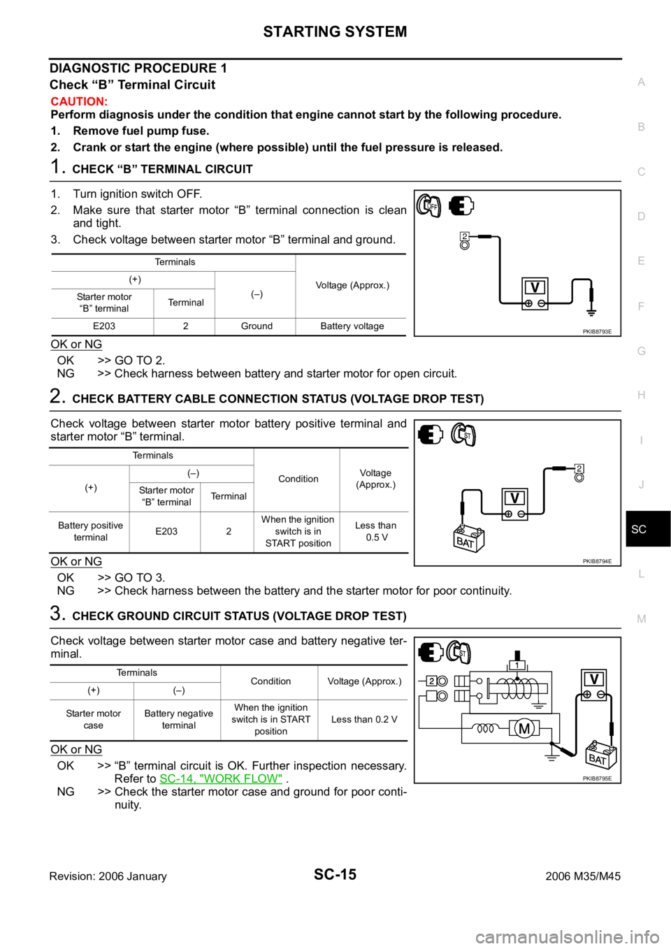
DIAGNOSTIC PROCEDURE 1
Check “B” Terminal Circuit
CAUTION:
Perform diagnosis under the condition that engine cannot start by the following procedure.
1. Remove fuel pump fuse.
2. Crank or start the engine (where possible) until the fuel pressure is released.
1. CHECK “B” TERMINAL CIRCUIT
1. Turn ignition switch OFF.
2. Make sure that starter motor “B” terminal connection is clean
and tight.
3. Check voltage between starter motor “B” terminal and ground.
OK or NG
OK >> GO TO 2.
NG >> Check harness between battery and starter motor for open circuit.
2. CHECK BATTERY CABLE CONNECTION STATUS (VOLTAGE DROP TEST)
Check voltage between starter motor battery positive terminal and
starter motor “B” terminal.
OK or NG
OK >> GO TO 3.
NG >> Check harness between the battery and the starter motor for poor continuity.
3. CHECK GROUND CIRCUIT STATUS (VOLTAGE DROP TEST)
Check voltage between starter motor case and battery negative ter-
minal.
OK or NG
OK >> “B” terminal circuit is OK. Further inspection necessary.
Refer to SC-14, "
WORK FLOW" .
NG >> Check the starter motor case and ground for poor conti-
nuity.
Terminals
Voltage (Approx.) (+)
(–)
Starter motor
“B” terminalTerminal
E203 2 Ground Battery voltage
PKIB8793E
Terminals
ConditionVoltage
(Approx.)
(+)(–)
Starter motor
“B” terminalTerminal
Battery positive
terminalE203 2 When the ignition
switch is in
START positionLess than
0.5 V
PKIB8794E
Terminals
Condition Voltage (Approx.)
(+) (–)
Starter motor
caseBattery negative
terminalWhen the ignition
switch is in START
positionLess than 0.2 V
PKIB8795E
Page 5153 of 5621

SC-16
STARTING SYSTEM
Revision: 2006 January2006 M35/M45
DIAGNOSTIC PROCEDURE 2
Check “S” Connector Circuit
CAUTION:
Perform diagnosis under the condition that engine cannot start by the following procedure.
1. Remove fuel pump fuse.
2. Crank or start the engine (where possible) until the fuel pressure is released.
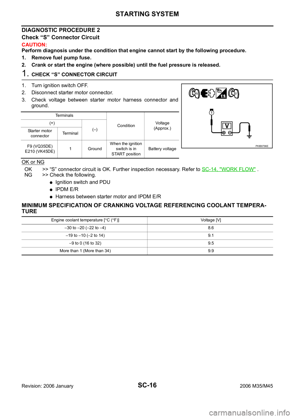
1. CHECK “S” CONNECTOR CIRCUIT
1. Turn ignition switch OFF.
2. Disconnect starter motor connector.
3. Check voltage between starter motor harness connector and
ground.
OK or NG
OK >> “S” connector circuit is OK. Further inspection necessary. Refer to SC-14, "WORK FLOW" .
NG >> Check the following.
Ignition switch and PDU
IPDM E/R
Harness between starter motor and IPDM E/R
MINIMUM SPECIFICATION OF CRANKING VOLTAGE REFERENCING COOLANT TEMPERA-
TURE
Te r m i n a l s
ConditionVoltage
(Approx.) (+)
(–)
Starter motor
connectorTe r m i n a l
F9 (VQ35DE)
E210 (VK45DE)1 GroundWhen the ignition
switch is in
START positionBattery voltage
PKIB8796E
Engine coolant temperature [C (F)] Voltage [V]
30 to 20 (22 to 4) 8.6
19 to 10 (2 to 14) 9.1
9 to 0 (16 to 32) 9.5
More than 1 (More than 34) 9.9
Page 5160 of 5621

CHARGING SYSTEM
SC-23
C
D
E
F
G
H
I
J
L
MA
B
SC
Revision: 2006 January2006 M35/M45
CHARGING SYSTEM PFP:00011
System Description NKS003NN
DESCRIPTION
The alternator provides DC voltage to operate the vehicle's electrical system and to keep the battery charged.
The voltage output is controlled by the IC regulator.
Power is supplied at all times
through 10A fuse [No. 36, located in the fuse, fusible link and relay block (J/B)]
to alternator terminal 4 (“S” terminal).
“B” terminal supplies power to charge the battery and operate the vehicle's electrical system. Output voltage is
controlled by the IC regulator at terminal 4 (“S” terminal) detecting the input voltage.
The alternator is grounded to the engine block.
With the ignition switch in the ON or START position, power is supplied
through 10A fuse [No. 14, located in the fuse block (J/B)]
to combination meter terminal 12 for the charge warning lamp.
Ground is supplied at signal
to combination meter terminal 22
through alternator terminal 3 (“L” terminal).
Then power and ground are supplied, the charge warning lamp will illuminate.
When the alternator is providing sufficient voltage with the engine running, the ground is opened and the
charge warning lamp will go off.
If the charge warning lamp illuminates with the engine running, a malfunction is indicated.
Ground is supplied
to alternator terminal 2 (“E” terminal)
through grounds E222, E223 and E224. (VQ35DE)
through ground E212. (VK45DE)
MALFUNCTION INDICATOR
The IC regulator warning function activates to illuminate the charge warning lamp, if any of the following symp-
toms occur while alternator is operating:
Excessive voltage is produced.
No voltage is produced.
Page 5169 of 5621

SC-32
CHARGING SYSTEM
Revision: 2006 January2006 M35/M45
PRELIMINARY INSPECTION
1. CHECK BATTERY TERMINALS CONNECTION
Check if battery terminals are clean and tight.
OK or NG
OK >> GO TO 2.
NG >> Repair battery terminals connection.
2. CHECK FUSE AND FUSIBLE LINK
Check for blown fuse and fusible link.
OK or NG
OK >> GO TO 3.
NG >> Be sure to eliminate cause of malfunction before installing new fuse.
3. CHECK “E” TERMINAL CONNECTION
Check if “E” terminal (alternator ground harness) is clean and tight.
OK or NG
OK >> GO TO 4.
NG >> Repair “E” terminal connection.
4. CHECK ALTERNATOR DRIVE BELT TENSION
Check alternator drive belt tension. Refer to EM-15, "
Checking Drive Belts" (VQ35DE) or EM-174, "Checking
Drive Belts" (VK45DE).
OK or NG
OK >> INSPECTION END
NG >> Repair as needed.
DIAGNOSTIC PROCEDURE 1
Check “L” Terminal Circuit (Open)
1. CHECK “L” TERMINAL CONNECTION
1. Turn ignition switch OFF.
2. Check if “L” terminal is clean and tight.
OK or NG
OK >> GO TO 2.
NG >> Repair “L” terminal connection. Confirm repair by performing complete Battery/Starting/Charging
system test. Refer to SC-28, "
Trouble Diagnoses with Battery/Starting/Charging System Tester
(Charging)" .
Unit Power source (Power supply terminals) Fuse and fusible link No.
Alternator Battery (“S” terminal) 36
Combination meter Ignition switch ON (“L” terminal) 14
Page 5170 of 5621

CHARGING SYSTEM
SC-33
C
D
E
F
G
H
I
J
L
MA
B
SC
Revision: 2006 January2006 M35/M45
2. CHECK “L” TERMINAL CIRCUIT (OPEN)
1. Disconnect alternator connector.
2. Apply ground to alternator harness connector terminal.
3. Check condition the charge warning lamp with the ignition
switch in the ON position.
OK or NG
OK >> Go to SC-31, "WORK FLOW" .
NG >> Check the following.
Harness for open between combination meter and alternator
Harness for open between combination meter and fuse
Charge warning lamp (Combination meter)
DIAGNOSTIC PROCEDURE 2
Check “L” Terminal Circuit (Short)
1. CHECK “L” TERMINAL CIRCUIT (SHORT)
1. Turn ignition switch OFF.
2. Disconnect alternator connector.
3. Turn ignition switch ON.
Charge warning lamp should illuminate?
YES >> Check the following.
Harness for short between combination meter and alternator
Charge warning lamp (Combination meter)
NO >> Go to SC-31, "
WORK FLOW" .
DIAGNOSTIC PROCEDURE 3
Check “S” Terminal Circuit
1. CHECK “S” TERMINAL CONNECTION
1. Turn ignition switch OFF.
2. Check if “S” terminal is clean and tight.
OK or NG
OK >> GO TO 2.
NG >> Repair “S” terminal connection. Confirm repair by performing complete Battery/Starting/Charging
system test. Refer to SC-28, "
Trouble Diagnoses with Battery/Starting/Charging System Tester
(Charging)" .
Alternator
connectorTerminal
GroundCondition
Ignition switch
positionCharge warning
lamp
F20 (VQ35DE)
E209 (VK45DE)3 ON illuminate
PKIB8807E
Page 5171 of 5621

SC-34
CHARGING SYSTEM
Revision: 2006 January2006 M35/M45
2. CHECK “S” TERMINAL CIRCUIT
Check voltage between alternator harness connector and ground.
OK or NG
OK >> Go to SC-31, "WORK FLOW" .
NG >> Check harness for open between alternator and fuse.
DIAGNOSTIC PROCEDURE 4
Check “B” Terminal Circuit
1. CHECK “B” TERMINAL CONNECTION
1. Turn ignition switch OFF.
2. Check if “B” terminal is clean and tight.
OK or NG
OK >> GO TO 2.
NG >> Repair “B” terminal connection. Confirm repair by performing complete Battery/Starting/Charging
system test. Refer to SC-28, "
Trouble Diagnoses with Battery/Starting/Charging System Tester
(Charging)" .
2. CHECK “B” TERMINAL CIRCUIT
Check voltage between alternator “B” terminal and ground.
OK or NG
OK >> GO TO 3.
NG >> Check harness for open between alternator and fusible
link.
3. CHECK “B” TERMINAL CONNECTION (VOLTAGE DROP TEST)
1. Start engine, then engine running at idle and warm.
2. Check voltage between battery positive terminal and alternator
“B” terminal.
OK or NG
OK >> Go to SC-31, "WORK FLOW" .
NG >> Check harness between battery and alternator for poor continuity.
Terminals
Voltage (Approx.) (+)
(–)
Alternator connector Terminal
F20 (VQ35DE)
E209 (VK45DE)4 Ground Battery voltage
PKIB8808E
Terminals
Voltage (Approx.) (+)
(–)
Alternator “B” terminal Terminal
E205 [VQ35DE (2WD)]
E202 [VQ35DE (AWD)/VK45DE]1 Ground Battery voltage
PKIB8809E
Te r m i n a l s
Voltage
(Approx.)
(+)(–)
Alternator “B” terminal Terminal
Battery positive
terminalE205 [VQ35DE (2WD)]
E202 [VQ35DE (AWD)/VK45DE]1 Less than 0.2 V
PKIB8810E
Page 5192 of 5621

AUTOMATIC DRIVE POSITIONER
SE-11
C
D
E
F
G
H
J
K
L
MA
B
SE
Revision: 2006 January2006 M35/M45
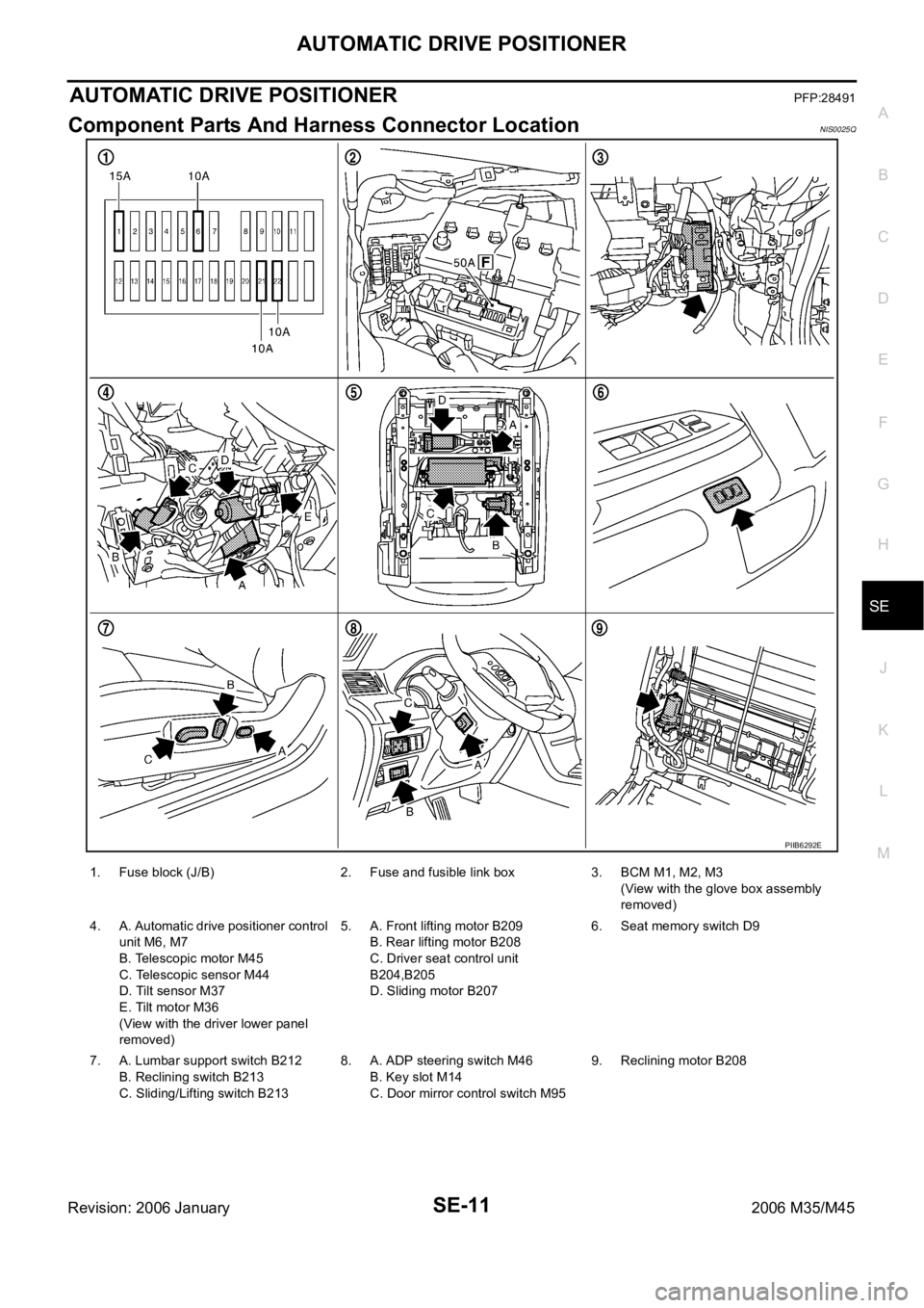
AUTOMATIC DRIVE POSITIONERPFP:28491
Component Parts And Harness Connector LocationNIS0025Q
PIIB6292E
1. Fuse block (J/B) 2. Fuse and fusible link box 3. BCM M1, M2, M3
(View with the glove box assembly
removed)
4. A. Automatic drive positioner control
unit M6, M7
B. Telescopic motor M45
C. Telescopic sensor M44
D. Tilt sensor M37
E. Tilt motor M36
(View with the driver lower panel
removed)5. A. Front lifting motor B209
B. Rear lifting motor B208
C. Driver seat control unit
B204,B205
D. Sliding motor B2076. Seat memory switch D9
7. A. Lumbar support switch B212
B. Reclining switch B213
C. Sliding/Lifting switch B2138. A. ADP steering switch M46
B. Key slot M14
C. Door mirror control switch M959. Reclining motor B208
Page 5211 of 5621

SE-30
AUTOMATIC DRIVE POSITIONER
Revision: 2006 January2006 M35/M45
Terminals and Reference Values for BCMNIS0025W
Terminals and Reference Value for Intelligent Key UnitNIS0025X
Termi-
nal Wire
colorItem ConditionVoltage (V)
(Approx)
11 V Power source (ACC)Ignition switch
(ACC or ON position)Battery voltage
37 LG Key switch signalKey switch ON (Key is inserted in key
slot)Battery voltage
Key switch OFF (Key is remove from
key slot)0
38 W Power source (IGN)Ignition switch
(ON or START position)Battery voltage
39 L CAN-H — —
40 P CAN-L — —
42 P Power source (Fuse) — Battery voltage
52 B Ground — 0
55 W Power source (Fusible link) — Battery voltage
62 V Drive side door switch ON (Open)
OFF (Closed) 0 Battery voltage
Te r m i -
nalWire
ColorItemCondition
Voltage (V)
Approx. Ignition
Switch
PositionOperation or Conditions
1 SB Power source (Fuse) — — Battery voltage
19 BR/Y Key switch signal LOCKInsert Intelligent Key into key slot. Battery voltage
Remove Intelligent Key from key slot. 0
20 B Ground ON — 0
27 V P range switch —Selector lever is in “P” position. 0
Other than above Battery voltage
37 P CAN-L — — —
38 L CAN-H — — —
40 B Ground ON — 0
41 Y Power source (Fuse) — — Battery voltage
56 B Ground ON — 0
57 L Power source (Fuse) — — Battery voltage
58 OA/T device power
supply —Wake up state Battery voltage
Sleep state 0
72 B Ground ON 0