navigation INFINITI M35 2006 Factory Owner's Manual
[x] Cancel search | Manufacturer: INFINITI, Model Year: 2006, Model line: M35, Model: INFINITI M35 2006Pages: 5621, PDF Size: 65.56 MB
Page 3603 of 5621

GW-84
REAR WINDOW DEFOGGER
Revision: 2006 January2006 M35/M45
Work FlowNIS0022P
1. Check the symptom and customer's requests.
2. Understand the outline of system. Refer to GW-73, "
System Description" .
3. According to the trouble diagnosis chart, repair or replace the cause of the malfunction. Refer to GW-84,
"Trouble Diagnoses Symptom Chart" .
4. Does rear window defogger operate normally? YES: GO TO 5, NO: GO TO 3.
5. INSPECTION END.
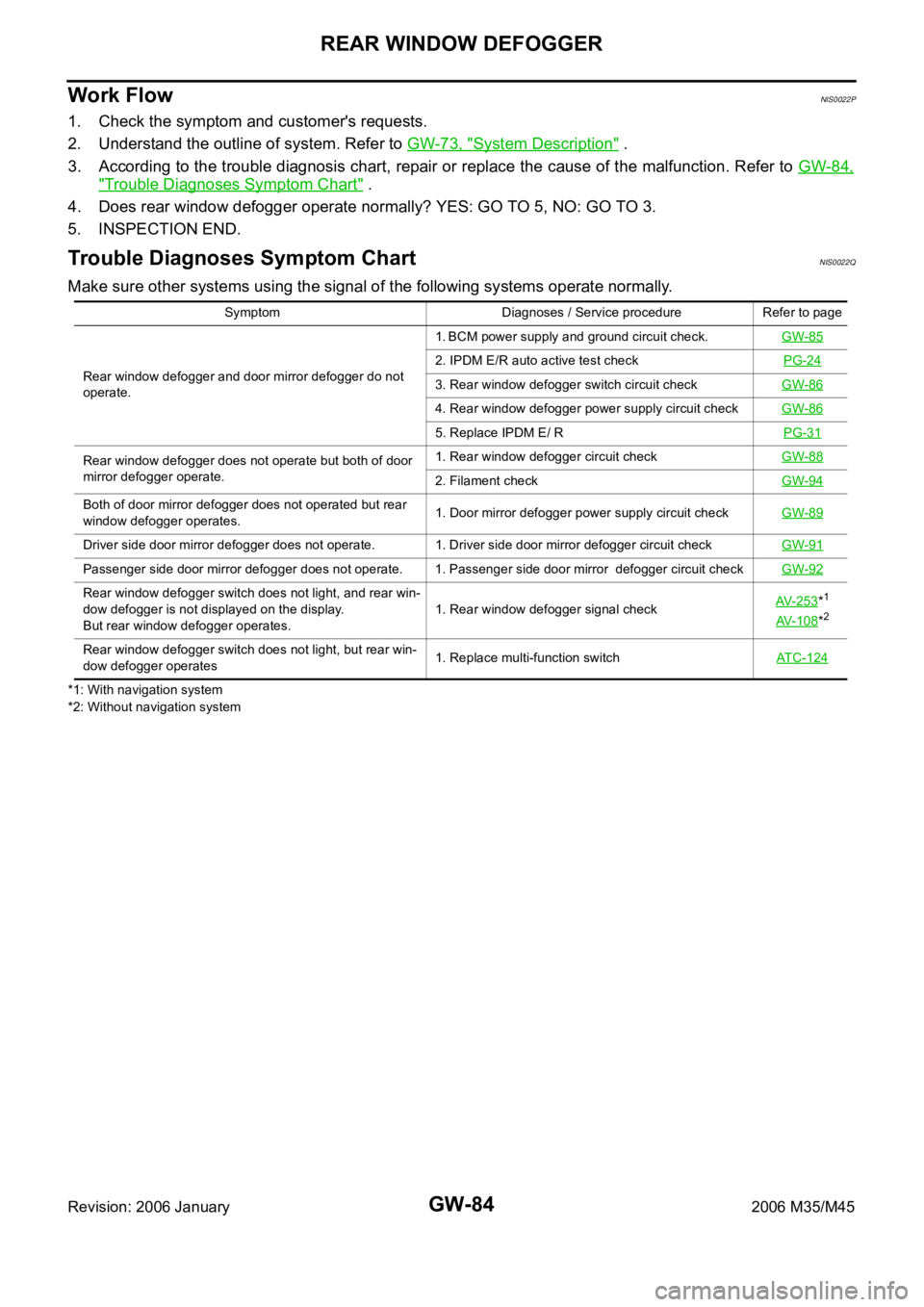
Trouble Diagnoses Symptom ChartNIS0022Q
Make sure other systems using the signal of the following systems operate normally.
*1: With navigation system
*2: Without navigation systemSymptom Diagnoses / Service procedure Refer to page
Rear window defogger and door mirror defogger do not
operate. 1. BCM power supply and ground circuit check.GW-85
2. IPDM E/R auto active test checkPG-24
3. Rear window defogger switch circuit checkGW-86
4. Rear window defogger power supply circuit checkGW-86
5. Replace IPDM E/ RPG-31
Rear window defogger does not operate but both of door
mirror defogger operate.1. Rear window defogger circuit checkGW-88
2. Filament checkGW-94
Both of door mirror defogger does not operated but rear
window defogger operates. 1. Door mirror defogger power supply circuit checkGW-89
Driver side door mirror defogger does not operate. 1. Driver side door mirror defogger circuit checkGW-91
Passenger side door mirror defogger does not operate. 1. Passenger side door mirror defogger circuit checkGW-92
Rear window defogger switch does not light, and rear win-
dow defogger is not displayed on the display.
But rear window defogger operates. 1. Rear window defogger signal checkAV-253*1
AV-108*2
Rear window defogger switch does not light, but rear win-
dow defogger operates1. Replace multi-function switchATC-124
Page 3605 of 5621

GW-86
REAR WINDOW DEFOGGER
Revision: 2006 January2006 M35/M45
Rear Window Defogger Switch Circuit CheckNIS0022S
1. CHECK REAR WINDOW DEFOGGER SWITCH OPERATION
With CONSULT-II
Check (“REAR DEF SW”, “IGN ON SW”) in DATA MONITOR mode with CONSULT-II.
OK or NG
OK >> Rear window defogger switch is OK.
NG >> GO TO 2.
2. CHECK AV LINE
Check AV line. Refer to AV- 2 5 3
(with navigation system), AV- 1 0 8 (without navigation system).
OK or NG
OK >> Check the condition of harness and connector.
NG >> The diagnosis is continued.
Rear Window Defogger Power Supply Circuit CheckNIS0022T
1. CHECK FUSE
Check 10A fuse [No.12, located in the fuse block (J/B)]
Check 20A fuse (No.75, located in the IPDM E/R)
Check 20A fuse (No.80, located in the IPDM E/R)
NOTE:
Refer to GW-73, "
Component Parts and Harness Connector Location" .
OK or NG
OK >> GO TO 2.
NG >> If fuse is blown out, be sure to eliminate cause of malfunction before installing new fuse, refer to
PG-3, "
POWER SUPPLY ROUTING CIRCUIT" .
2. CHECK POWER SUPPLY CIRCUIT
1. Turn ignition switch OFF.
2. Remove rear window defogger relay.
3. Turn ignition switch ON.
4. Check voltage between rear window defogger relay connector and ground.
OK or NG
OK >> GO TO 3.
NG >> Repair or replace harness between fuse block (J/B) and rear window defogger relay. When rear window defogger switch is turned to ON
REAR DEF SW : ON
When ignition switch is turned to ON
IGN ON SW : ON
PIIA2373E
Terminals
Voltage (V)
(Approx.) (+)
(–) Rear window
defogger relay
connectorTerminal
E361
Ground Battery voltage 3
6
PIIB5994E
Page 3703 of 5621
![INFINITI M35 2006 Factory Owners Manual LAN-34
[CAN]
CAN COMMUNICATION
Revision: 2006 January2006 M35/M45
CAN COMMUNICATIONPFP:23710
System DescriptionNKS003XV
CAN (Controller Area Network) is a serial communication line for real time appli INFINITI M35 2006 Factory Owners Manual LAN-34
[CAN]
CAN COMMUNICATION
Revision: 2006 January2006 M35/M45
CAN COMMUNICATIONPFP:23710
System DescriptionNKS003XV
CAN (Controller Area Network) is a serial communication line for real time appli](/img/42/57023/w960_57023-3702.png)
LAN-34
[CAN]
CAN COMMUNICATION
Revision: 2006 January2006 M35/M45
CAN COMMUNICATIONPFP:23710
System DescriptionNKS003XV
CAN (Controller Area Network) is a serial communication line for real time application. It is an on-vehicle mul-
tiplex communication line with high data communication speed and excellent error detection ability. Many elec-
tronic control units are equipped onto a vehicle, and each control unit shares information and links with other
control units during operation (not independent). In CAN communication, control units are connected with 2
communication lines (CAN H line, CAN L line) allowing a high rate of information transmission with less wiring.
Each control unit transmits/receives data but selectively reads required data only.
CAN Communication UnitNKS003XW
Go to CAN system, when selecting your CAN system type from the following table.
: Applicable
SYSTEM DIAGRAM
Ty pe 1
Body typeSedan
Axle 2WD AWD
Engine VQ35DE/VK45DE VQ35DE
TransmissionA/T
Brake controlVDC
Navigation system
Pre-crash seat belt
Adaptive front-lighting system
ICC system
Lane departure warning
Rear active steer
CAN system type 12 3456789101112131415
CAN system trouble diagnosisLA
N-
48
LA
N-
89
LA
N-
130
LA
N-
177
LA
N-
224
LA
N-
275
LA
N-
321
LA
N-
367
LA
N-
417
LA
N-
467
LA
N-
521
LA
N-
564
LA
N-
607
LA
N-
656
LA
N-
705
PKIB8588E
Page 4723 of 5621

LT-296
ILLUMINATION
Revision: 2006 January2006 M35/M45
ILLUMINATION OPERATION BY LIGHTING SWITCH
With the lighting switch in the 1ST or 2ND position (or if the auto light system is activated), the BCM receives
input signal requesting the illumination lamps to illuminate. This input signal is communicated to the IPDM E/R
across the CAN communication lines. The CPU located in the IPDM E/R controls the tail lamp relay coil,
which, when energized, directs power
through IPDM E/R terminal 21
to combination meter terminal 13
to LDW switch (illumination) terminal 5 (with lane departure warning)
to VDC off switch (illumination) terminal 3
to trunk lid opener switch (illumination) terminal 3
to combination switch (spiral cable) terminal 24
to door mirror remote control switch (illumination) terminal 16
to AFS switch (illumination) terminal 5 (with AFS)
to rear sunshade front switch (illumination) terminal 5 (with rear control switch)
to A/T illumination terminal 1
to snow mode switch (illumination) terminal 5 (AWD models)
to rear control cancel switch (illumination) terminal 4 (with rear control switch)
to clock terminal 3
to multifunction switch terminal 3
to audio unit terminal 9
to DVD player terminal 18 (with DVD player)
to NAVI control unit terminal 61 (with navigation system)
to AV control unit terminal 61 (without navigation system)
to climate controlled seat switch driver side (illumination) terminal 7 (with climate controlled seat)
to climate controlled seat switch passenger side (illumination) terminal 7 (with climate controlled seat)
to ashtray illumination (rear LH) terminal 1
to ashtray illumination (rear RH) terminal 1
to illumination control switch terminal 1
to cigarette lighter socket (illumination) terminal 2
to map lamp (illumination) terminal 8
to power window main switch illumination terminal 1
to glove box lamp terminal 1
to rear control switch terminal 2
to rear power seat switch RH (illumination) terminal 4 (with rear control switch)
to rear heated seat switch RH (illumination) terminal 7 (with rear control switch)
to rear sunshade cancel relay terminal 6 (with rear control switch)
to automatic return cancel switch (illumination) terminal 4 (with rear control switch)
to rear power seat switch LH (illumination) terminal 4 (with rear control switch) and
to rear heated seat switch LH (illumination) terminal 7 (with rear control switch),
through Intelligent Key unit terminal 12
to push button ignition switch (illumination) terminal 3.
Ground is supplied
to combination meter terminal 14
to combination meter terminal 9, 10 and 11
to push button ignition switch (illumination) terminal 2
to LDW switch (illumination) terminal 4 (with lane departure warning)
to VDC off switch (illumination) terminal 4
to trunk lid opener switch (illumination) terminal 4
to combination switch (spiral cable) terminal 25
Page 4828 of 5621

PG-1
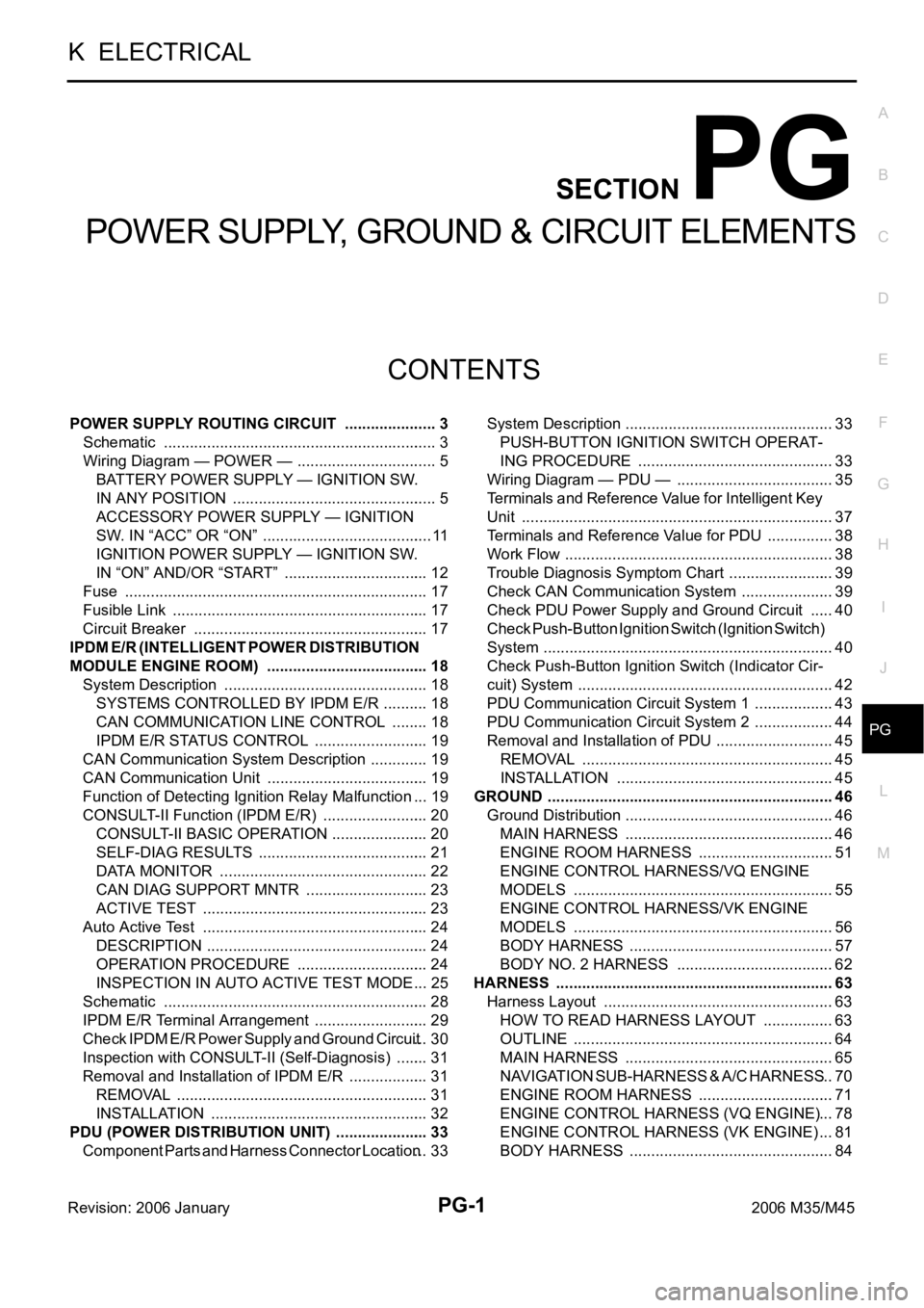
POWER SUPPLY, GROUND & CIRCUIT ELEMENTS
K ELECTRICAL
CONTENTS
C
D
E
F
G
H
I
J
L
M
SECTION PG
A
B
PG
Revision: 2006 January2006 M35/M45
POWER SUPPLY, GROUND & CIRCUIT ELEMENTS
POWER SUPPLY ROUTING CIRCUIT ...................... 3
Schematic ................................................................ 3
Wiring Diagram — POWER — ................................. 5
BATTERY POWER SUPPLY — IGNITION SW.
IN ANY POSITION ................................................ 5
ACCESSORY POWER SUPPLY — IGNITION
SW. IN “ACC” OR “ON” ........................................ 11
IGNITION POWER SUPPLY — IGNITION SW.
IN “ON” AND/OR “START” .................................. 12
Fuse ....................................................................... 17
Fusible Link ............................................................ 17
Circuit Breaker ....................................................... 17
IPDM E/R (INTELLIGENT POWER DISTRIBUTION
MODULE ENGINE ROOM) ...................................... 18
System Description ................................................ 18
SYSTEMS CONTROLLED BY IPDM E/R ........... 18
CAN COMMUNICATION LINE CONTROL ......... 18
IPDM E/R STATUS CONTROL ........................... 19
CAN Communication System Description .............. 19
CAN Communication Unit ...................................... 19
Function of Detecting Ignition Relay Malfunction ... 19
CONSULT-II Function (IPDM E/R) ......................... 20
CONSULT-II BASIC OPERATION ....................... 20
SELF-DIAG RESULTS ........................................ 21
DATA MONITOR ................................................. 22
CAN DIAG SUPPORT MNTR ............................. 23
ACTIVE TEST ..................................................... 23
Auto Active Test ..................................................... 24
DESCRIPTION .................................................... 24
OPERATION PROCEDURE ............................... 24
INSPECTION IN AUTO ACTIVE TEST MODE ... 25
Schematic .............................................................. 28
IPDM E/R Terminal Arrangement ........................... 29
Check IPDM E/R Power Supply and Ground Circuit ... 30
Inspection with CONSULT-II (Self-Diagnosis) ........ 31
Removal and Installation of IPDM E/R ................... 31
REMOVAL ........................................................
... 31
INSTALLATION ................................................... 32
PDU (POWER DISTRIBUTION UNIT) ...................... 33
Component Parts and Harness Connector Location ... 33System Description ................................................. 33
PUSH-BUTTON IGNITION SWITCH OPERAT-
ING PROCEDURE .............................................. 33
Wiring Diagram — PDU — ..................................... 35
Terminals and Reference Value for Intelligent Key
Unit ......................................................................... 37
Terminals and Reference Value for PDU ................ 38
Work Flow ............................................................... 38
Trouble Diagnosis Symptom Chart ......................... 39
Check CAN Communication System ...................... 39
Check PDU Power Supply and Ground Circuit ...... 40
Check Push-Button Ignition Switch (Ignition Switch)
System .................................................................... 40
Check Push-Button Ignition Switch (Indicator Cir-
cuit) System ............................................................ 42
PDU Communication Circuit System 1 ................... 43
PDU Communication Circuit System 2 ................... 44
Removal and Installation of PDU ............................ 45
REMOVAL ........................................................
... 45
INSTALLATION ................................................... 45
GROUND ................................................................... 46
Ground Distribution ................................................. 46
MAIN HARNESS ................................................. 46
ENGINE ROOM HARNESS ................................ 51
ENGINE CONTROL HARNESS/VQ ENGINE
MODELS ............................................................. 55
ENGINE CONTROL HARNESS/VK ENGINE
MODELS ............................................................. 56
BODY HARNESS ................................................ 57
BODY NO. 2 HARNESS ..................................... 62
HARNESS ................................................................. 63
Harness Layout ...................................................... 63
HOW TO READ HARNESS LAYOUT ................. 63
OUTLINE ............................................................. 64
MAIN HARNESS ................................................. 65
NAVIGATION SUB-HARNESS & A/C HARNESS ... 70
ENGINE ROOM HARNESS ................................ 71
ENGINE CONTROL HARNESS (VQ ENGINE) ... 78
ENGINE CONTROL HARNESS (VK ENGINE) ... 81
BODY HARNESS ................................................ 84
Page 4897 of 5621

PG-70
HARNESS
Revision: 2006 January2006 M35/M45
NAVIGATION SUB-HARNESS & A/C HARNESS
TKIT0447E