oil capacity INFINITI M35 2006 Factory Owner's Manual
[x] Cancel search | Manufacturer: INFINITI, Model Year: 2006, Model line: M35, Model: INFINITI M35 2006Pages: 5621, PDF Size: 65.56 MB
Page 4809 of 5621

MA-32
CHASSIS AND BODY MAINTENANCE
Revision: 2006 January2006 M35/M45
Changing Transfer FluidNLS00083
CAUTION:
When draining fluid, protect exhaust tube flange with cover.
1. Drain fluid from drain plug and refill with new gear fluid.
(For details, refer to TF-9, "
Replacement" .)
2. Check fluid level.
CAUTION:
Carefully fill the fluid. (Fill up for Approx. 3 minutes.)
Checking Propeller ShaftNLS00084
Check propeller shaft for damage, looseness or grease leakage.
Checking Differential Gear OilNLS00085
Check for oil leakage.
(For details, refer to FFD-8, "
Checking Differential Gear Oil" and
RFD-9, "
Checking Differential Gear Oil" .) Fluid grade:
Genuine NISSAN Matic D ATF (Continental U.S.
and Alaska) or Canada NISSAN Automatic Trans-
mission Fluid
Refer to MA-12, "
RECOMMENDED FLUIDS AND
LUBRICANTS" .
Fluid capacity:
: Approx. 1.25 (2-5/8 US pt, 2-1/4 lmp pt)
Drain plug:
: 29.4 Nꞏm (3.0 kg-m, 22 ft-lb)
Filler plug:
: 35 Nꞏm (3.6 kg-m, 26 ft-lb)SDIA2087E
Tightening torque:
Refer to PR-6, "
REAR PROPELLER SHAFT"
SMA118A
SMA012C
Page 4810 of 5621

CHASSIS AND BODY MAINTENANCE
MA-33
C
D
E
F
G
H
I
J
K
MA
B
MA
Revision: 2006 January2006 M35/M45
Changing Differential Gear OilNLS00086
1. Drain oil from drain plug and refill with new gear oil.
(For details, refer to FFD-8, "
Changing Differential Gear Oil" and RFD-9, "Changing Differential Gear Oil"
.)
2. Check oil level.
Balancing Wheels (Bonding Weight Type)NLS00087
REMOVAL
1. Remove inner and outer balance weights from the road wheel.
CAUTION:
Be careful not to scratch the road wheel during removal.
2. Using releasing agent, remove double-faced adhesive tape from the road wheel.
CAUTION:
Be careful not to scratch the road wheel during removal.
After removing double-faced adhesive tape, wipe clean traces of releasing agent from the road
wheel.
WHEEL BALANCE ADJUSTMENT
If a tire balance machine has adhesion balance weight mode settings and drive-in weight mode setting,
select and adjust a drive-in weight mode suitable for road wheels.
1. Set road wheel on wheel balancer using the center hole as a guide. Start the tire balance machine.
2. When inner and outer unbalance values are shown on the wheel balancer indicator, multiply outer unbal-
ance value by 5/3 to determine balance weight that should be used. Select the outer balance weight with
a value closest to the calculated value above and install it to the designated outer position of, or at the
designated angle in relation to the road wheel.
CAUTION:
Do not install the inner balance weight before installing the outer balance weight. Oil grade and Viscosity:
Refer to MA-12, "
RECOMMENDED FLUIDS
AND LUBRICANTS" .
Capacity:
Front final drive (F160A)
0.65 (1 - 3/8 US pt, 1 - 1/8 lmp pt)
Rear final drive (R200)
1.4 (3 US pt, 2 - 1/2 lmp pt)
Filler plug:
Front final drive
: 34.5 N-m (3.5 kg-m, 25 ft-lb)
Rear final drive
: 34.5 N-m (3.5 kg-m, 25 ft-lb)
Drain plug:
Front final drive
: 34.5 N-m (3.5 kg-m, 25 ft-lb)
Rear final drive
: 34.5 N-m (3.5 kg-m, 25 ft-lb)
SDIA1151E
Page 4817 of 5621

MA-40
SERVICE DATA AND SPECIFICATIONS (SDS)
Revision: 2006 January2006 M35/M45
SERVICE DATA AND SPECIFICATIONS (SDS)PFP:00030
Standard and LimitNLS0008J
BELT DEFLECTION AND TENSION (VQ35DE)
*: If belt tension gauge cannot be installed at check points shown, check drive belt tension at different location on the belt.
BELT DEFLECTION AND TENSION (VK45DE)
ENGINE COOLANT CAPACITY (APPROXIMATE) (VQ35DE)
Unit: (US qt, lmp qt)
ENGINE COOLANT CAPACITY (APPROXIMATE) (VK45DE)
Unit: (US qt, lmp qt)
RADIATOR
Unit: kPa (kg/cm2 , psi)
ENGINE OIL CAPACITY (APPROXIMATE) (VQ35DE)
Unit: (US qt, lmp qt) Deflection adjustment Unit: mm (in) Tension adjustment* Unit: N (kg, lb)
Used belt
New beltUsed belt
New belt
Limit After adjustment Limit After adjustment
Alternator and
power steering
oil pump belt7 (0.28)4 - 5
(0.16 - 0.20)3.5 - 4.5
(0.138 - 0.177)294 (30, 66)730 - 818
(74.5 - 83.5,
164 - 184)838 - 926
(85.5 - 94.5,
188 - 208)
A/C compressor
belt12 (0.47)9 - 10
(0.35 - 0.39)8 - 9
(0.31 - 0.35)196 (20, 44)348 - 436
(35.5 - 44.5,
78 - 98)470 - 559
(48 - 57,
106 - 126)
Applied pushing
force98 N (10 kg, 22 lb) —
KBIA1731J
Tension of drive belts Auto-adjustment by auto tensioner
Engine coolant capacity (With reservoir tank at “MAX” level) 8.9 (9-3/8, 7-7/8)
Reservoir tank engine coolant capacity (At “MAX” level) 0.6 (5/8, 1/2)
Engine coolant capacity (With reservoir tank at “MAX” level) 10.4 (11, 9-1/8)
Reservoir tank engine coolant capacity (At “MAX” level) 0.6 (5/8, 1/2)
Cap relief pressureStandard 78 - 98 (0.8 - 1.0, 11 - 14)
Limit 59 (0.6, 9)
Leakage testing pressure157 (1.6, 23)
Drain and refill With oil filter change 4.7 (5, 4-1/8)
Without oil filter change 4.4 (4-5/8, 3-7/8)
Dry engine (Overhaul) 5.4 (5-3/4, 4-3/4)
Page 4818 of 5621

SERVICE DATA AND SPECIFICATIONS (SDS)
MA-41
C
D
E
F
G
H
I
J
K
MA
B
MA
Revision: 2006 January2006 M35/M45
ENGINE OIL CAPACITY (APPROXIMATE) (VK45DE)
Unit: (US qt, lmp qt)
SPARK PLUG (PLATINUM-TIPPED TYPE) (VQ35DE)
SPARK PLUG (PLATINUM-TIPPED TYPE) (VK45DE)
WHEEL BALANCE
Drain and refillWith oil filter change 5.5 (5-3/4, 4-7/8)
Without oil filter change 4.9 (5-1/8, 4-1/4)
Dry engine (Overhaul)6.7 (7-1/8, 5-7/8)
MakeNGK
Ty p eStandard PLFR5A-11
Hot PLFR4A-11
Cold PLFR6A-11
Spark plug gapNominal: 1.1mm (0.043 in)
Make NGK
TypeStandard PLFR5A-11
Hot PLFR4A-11
Cold PLFR6A-11
Spark plug gapNominal: 1.1mm (0.043 in)
Maximum allowable unbalanceDynamic (At rim flange) Less than 7 g (0.25 oz) (one side)
Static (At rim flange) Less than 14 g (0.50 oz)
Page 4998 of 5621

SERVICE DATA AND SPECIFICATIONS (SDS)
PS-45
C
D
E
F
H
I
J
K
L
MA
B
PS
Revision: 2006 January2006 M35/M45
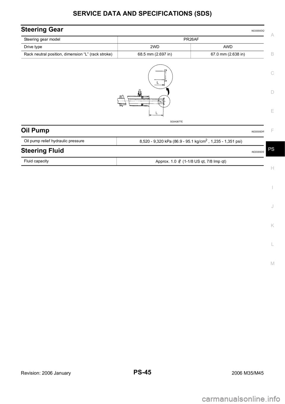
Steering GearNGS000DQ
Oil PumpNGS000DR
Steering FluidNGS000DS
Steering gear model PR26AF
Drive type 2WD AWD
Rack neutral position, dimension “L” (rack stroke) 68.5 mm (2.697 in) 67.0 mm (2.638 in)
SGIA0877E
Oil pump relief hydraulic pressure
8,520 - 9,320 kPa (86.9 - 95.1 kg/cm2 , 1,235 - 1,351 psi)
Fluid capacity
Approx. 1.0 (1-1/8 US qt, 7/8 Imp qt)
Page 5052 of 5621

DIFFERENTIAL GEAR OIL
RFD-9
C
E
F
G
H
I
J
K
L
MA
B
RFD
Revision: 2006 January2006 M35/M45
DIFFERENTIAL GEAR OILPFP:KLD30
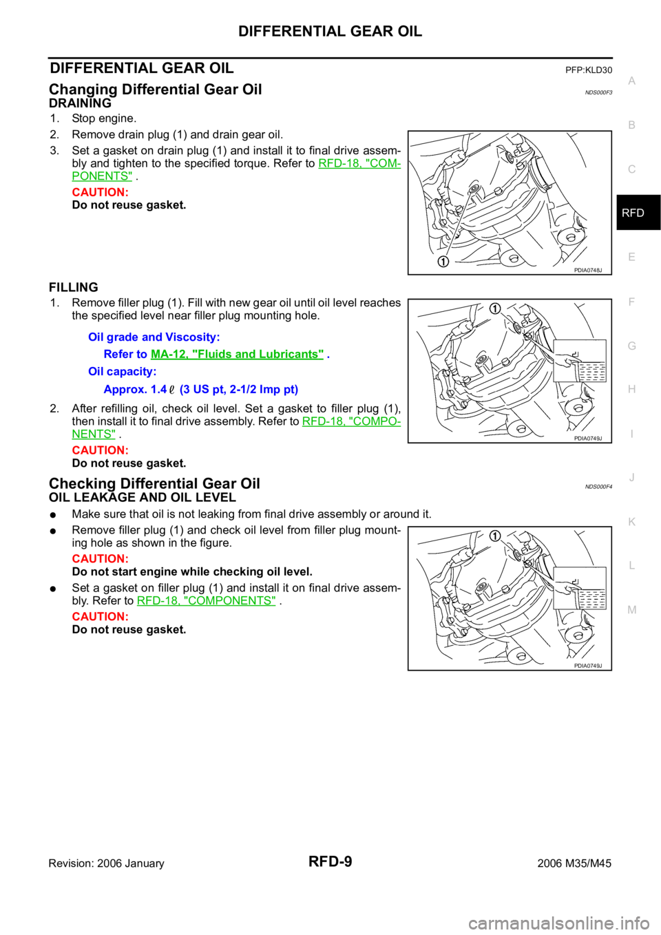
Changing Differential Gear OilNDS000F3
DRAINING
1. Stop engine.
2. Remove drain plug (1) and drain gear oil.
3. Set a gasket on drain plug (1) and install it to final drive assem-
bly and tighten to the specified torque. Refer to RFD-18, "
COM-
PONENTS" .
CAUTION:
Do not reuse gasket.
FILLING
1. Remove filler plug (1). Fill with new gear oil until oil level reaches
the specified level near filler plug mounting hole.
2. After refilling oil, check oil level. Set a gasket to filler plug (1),
then install it to final drive assembly. Refer to RFD-18, "
COMPO-
NENTS" .
CAUTION:
Do not reuse gasket.
Checking Differential Gear OilNDS000F4
OIL LEAKAGE AND OIL LEVEL
Make sure that oil is not leaking from final drive assembly or around it.
Remove filler plug (1) and check oil level from filler plug mount-
ing hole as shown in the figure.
CAUTION:
Do not start engine while checking oil level.
Set a gasket on filler plug (1) and install it on final drive assem-
bly. Refer to RFD-18, "
COMPONENTS" .
CAUTION:
Do not reuse gasket.
PDIA0748J
Oil grade and Viscosity:
Refer to MA-12, "
Fluids and Lubricants" .
Oil capacity:
Approx. 1.4 (3 US pt, 2-1/2 Imp pt)
PDIA0749J
PDIA0749J
Page 5080 of 5621

SERVICE DATA AND SPECIFICATIONS (SDS)
RFD-37
C
E
F
G
H
I
J
K
L
MA
B
RFD
Revision: 2006 January2006 M35/M45
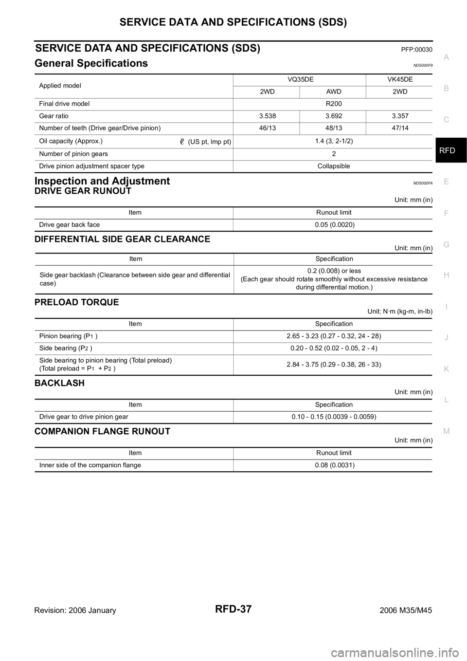
SERVICE DATA AND SPECIFICATIONS (SDS)PFP:00030
General SpecificationsNDS000F9
Inspection and AdjustmentNDS000FA
DRIVE GEAR RUNOUT
Unit: mm (in)
DIFFERENTIAL SIDE GEAR CLEARANCE
Unit: mm (in)
PRELOAD TORQUE
Unit: Nꞏm (kg-m, in-lb)
BACKLASH
Unit: mm (in)
COMPANION FLANGE RUNOUT
Unit: mm (in) Applied modelVQ35DE VK45DE
2WD AWD 2WD
Final drive modelR200
Gear ratio 3.538 3.692 3.357
Number of teeth (Drive gear/Drive pinion) 46/13 48/13 47/14
Oil capacity (Approx.)
(US pt, lmp pt)1.4 (3, 2-1/2)
Number of pinion gears2
Drive pinion adjustment spacer type Collapsible
Item Runout limit
Drive gear back face 0.05 (0.0020)
Item Specification
Side gear backlash (Clearance between side gear and differential
case)0.2 (0.008) or less
(Each gear should rotate smoothly without excessive resistance
during differential motion.)
Item Specification
Pinion bearing (P
1 ) 2.65 - 3.23 (0.27 - 0.32, 24 - 28)
Side bearing (P
2 ) 0.20 - 0.52 (0.02 - 0.05, 2 - 4)
Side bearing to pinion bearing (Total preload)
(Total preload = P
1 + P2 )2.84 - 3.75 (0.29 - 0.38, 26 - 33)
Item Specification
Drive gear to drive pinion gear 0.10 - 0.15 (0.0039 - 0.0059)
Item Runout limit
Inner side of the companion flange 0.08 (0.0031)
Page 5180 of 5621

SERVICE DATA AND SPECIFICATIONS (SDS)
SC-43
C
D
E
F
G
H
I
J
L
MA
B
SC
Revision: 2006 January2006 M35/M45
SERVICE DATA AND SPECIFICATIONS (SDS)PFP:00030
BatteryNKS003NT
StarterNKS003NU
AlternatorNKS003NV
*: Adjustment range of power generation voltage variable control is 11.4 - 15.6 V. Ty p e110D26L
20 hour rate capacity [V - Ah] 12 - 75
Cold cranking current (For reference value) [A] 720
Applied modelVK45DE VQ35DE VQ35DE
2WD AWD
Ty p eM2T85771 S114-880 S114-881
MITSUBISHI
makeHITACHI make
Reduction gear type
System voltage [V] 12
No-loadTerminal voltage [V] 11
Current [A] Less than 145 Less than 90
Revolution [rpm] More than 3,300 More than 2,880
Minimum diameter of commutator [mm (in)] 31.4 (1.236) 28.0 (1.102)
Minimum length of brush [mm (in)] 11.0 (0.433) 10.5 (0.413)
Brush spring tension [N (kg, lb)]26.7 - 36.1
(2.72 - 3.68,
6.80 - 8.12)16.2 (1.65, 3.6)
Clearance between bearing metal and armature shaft [mm (in)] Less than 0.2 (0.008)
Clearance between pinion front edge and pinion stopper [mm (in)]0.5 - 2.0
(0.020 - 0.079)0.3 - 2.5 (0.012 - 0.098)
Applied model VK45DE VQ35DE
Ty p eA3TJ0591 A3TJ0691
MITSUBISHI make
Nominal rating [V - A] 12 -150
Ground polarityNegative
Minimum revolution under no-load (When 13.5 V is
applied)[rpm] Less than 1,300
Hot output current (When 13.5 V is applied) [A/rpm]More than 35/1,300
More than 105/2,500
More than 136/5,000
Regulated output voltage [V] 14.1 - 14.7 *
Minimum length of brush [mm (in)] More than 5.00 (0.197)
Brush spring pressure [N (g, oz)] 4.1 - 5.3 (418 - 540, 14.8 - 19.1)
Slip ring minimum outer diameter [mm (in)] More than 22.1 (0.870)
Rotor (Field coil) resistance [
] 1.6 - 2.0
Page 5474 of 5621

TRANSFER FLUID
TF-9
C
E
F
G
H
I
J
K
L
MA
B
TF
Revision: 2006 January2006 M35/M45
TRANSFER FLUIDPFP:31001
ReplacementNDS000D9
DRAINING
1. Run the vehicle to warm up the transfer unit sufficiently.
2. Stop the engine, and remove the drain plug to drain the transfer
fluid.
CAUTION:
When draining fluid, protect exhaust tube flange with cover.
3. Apply sealant to drain plug. Install drain plug on transfer and
tighten to the specified torque. Refer to TF-45, "
COMPO-
NENTS" .
Use Genuine Silicone RTV or equivalent. Refer to GI-48,
"Recommended Chemical Products and Sealants" .
CAUTION:
Remove old sealant adhering to mounting surfaces. Also
remove any moisture, oil, or foreign material adhering to application and mounting surfaces.
FILLING
1. Remove filler plug and add transfer fluid until fluid level reaches
the specified limit near filler plug mounting hole.
CAUTION:
Carefully fill the fluid. (Fill up for approx. 3 minutes.)
2. Leave the vehicle for 3 minutes, and check the fluid level again.
3. Set a new gasket onto filler plug and install it on transfer and
tighten to the specified torque. Refer to TF-45, "
COMPO-
NENTS" .
CAUTION:
Do not reuse gasket.
InspectionNDS000DA
FLUID LEAKAGE AND FLUID LEVEL
1. Check if fluid is leaking from transfer or around it.
2. Check fluid level from filler plug mounting hole as shown in the
figure.
CAUTION:
Never start engine while checking fluid level.
3. Before installing filler plug, set a new gasket. Install filler plug on
transfer and tighten to the specified torque. Refer to TF-45,
"COMPONENTS" .
CAUTION:
Do not reuse gasket.
SDIA2087E
Fluid capacity
: Approx. 1.25 (2-5/8 US pt, 2-1/4 lmp pt)
SDIA2028E
SDIA2028E