wheel bolt torque INFINITI M35 2006 Factory Owner's Guide
[x] Cancel search | Manufacturer: INFINITI, Model Year: 2006, Model line: M35, Model: INFINITI M35 2006Pages: 5621, PDF Size: 65.56 MB
Page 5429 of 5621
![INFINITI M35 2006 Factory Owners Guide STC-14
[RAS]
REAR ACTIVE STEER
Revision: 2006 January2006 M35/M45
Disassembly and AssemblyNGS000E6
COMPONENTS
DISASSEMBLY
1. Remove mounting bolts of RAS motor assembly, and then remove RAS motor asse INFINITI M35 2006 Factory Owners Guide STC-14
[RAS]
REAR ACTIVE STEER
Revision: 2006 January2006 M35/M45
Disassembly and AssemblyNGS000E6
COMPONENTS
DISASSEMBLY
1. Remove mounting bolts of RAS motor assembly, and then remove RAS motor asse](/img/42/57023/w960_57023-5428.png)
STC-14
[RAS]
REAR ACTIVE STEER
Revision: 2006 January2006 M35/M45
Disassembly and AssemblyNGS000E6
COMPONENTS
DISASSEMBLY
1. Remove mounting bolts of RAS motor assembly, and then remove RAS motor assembly, ground terminal,
O-ring from RAS actuator.
2. Remove mounting bolt of rear wheel steering angle sensor, and then remove rear wheel steering angle
sensor, O-ring from RAS actuator.
INSPECTION AFTER DISASSEMBLY
Check RAS actuator bracket (rear wheel steering angle sensor mounting area) for crush, deformation, cracks,
or other damage. Replace the RAS actuator malfunction is detected.
ASSEMBLY
Assembly is the reverse order of disassembly. For tightening torque, refer to STC-14, "COMPONENTS" .
After assembling RAS actuator assembly (after removing and installing rear wheel angle sensor and RAS
motor), perform the neutral position adjustment.
Neutral Position AdjustmentNGS000E7
Adjust neutral position after performing the following procedure.
Removing and installing or replacing the RAS actuator assembly
Disassembling the RAS actuator assembly (when removing rear wheel steering angle sensor and RAS
motor)
CAUTION:
Perform the neutral position adjustment after installing the RAS actuator assembly to the vehicle.
Before that, remove the rear lower link from the RAS actuator.
1. Disconnect harness connector and remove rear wheel steering angle sensor from the RAS actuator
assembly.
2. Disconnect RAS motor harness connector.
3. Turn ignition switch ON.
1. Ground terminal 2. RAS motor assembly 3. O-ring
4. RAS actuator 5. Rear wheel steering angle sensor
Refer to GI-11, "
Components" , for the symbols in the figure.
SGIA1052J
Page 5430 of 5621
![INFINITI M35 2006 Factory Owners Guide REAR ACTIVE STEER
STC-15
[RAS]
C
D
E
F
H
I
J
K
L
MA
B
STC
Revision: 2006 January2006 M35/M45
4. Supply 6 V voltage by connecting the four 1.5 V batteries in a
series. Connect them to the RAS motor con INFINITI M35 2006 Factory Owners Guide REAR ACTIVE STEER
STC-15
[RAS]
C
D
E
F
H
I
J
K
L
MA
B
STC
Revision: 2006 January2006 M35/M45
4. Supply 6 V voltage by connecting the four 1.5 V batteries in a
series. Connect them to the RAS motor con](/img/42/57023/w960_57023-5429.png)
REAR ACTIVE STEER
STC-15
[RAS]
C
D
E
F
H
I
J
K
L
MA
B
STC
Revision: 2006 January2006 M35/M45
4. Supply 6 V voltage by connecting the four 1.5 V batteries in a
series. Connect them to the RAS motor connector (motor side),
and then operate the motor and adjust the rack in the neutral
position (A).
CAUTION:
Do not supply 12 V voltage (battery, etc) to the RAS motor.
NOTE:
For right stroke, connect positive probe to the RAS motor con-
nector terminal 1. For left stroke, connect it to the terminal 2.
5. Install rear wheel steering angle sensor with O-ring to the RAS
actuator assembly. Temporarily tighten the mounting bolts in the specified torque that the sensor can be
moved by hand.
6. Turn and adjust the rear wheel steering angle sensor so as to make each sensor signal of “DATA MONI-
TOR” mode to the following standard with CONSULT-II.
CAUTION:
During DATA MONITOR mode, “MONITORING ERROR” is displayed. But there is not malfunction
in this procedure.
7. Tighten rear wheel steering angle sensor mounting bolts.
8. Perform “ERASE” with CONSULT-II, and then erase the error memory of rear wheel steering angle sen-
sor. Refer to STC-29, "
How to Erase Self-Diagnostic Results" .
9. Perform CONSULT-II “SELF-DIAG RESULTS” again, and then make sure that there is no malfunction.
Refer to STC-28, "
SELF-DIAG RESULT MODE" . Full stroke (B) : 6.8 - 7.2 mm (0.268 - 0.283 in)
STEERING ANG () L - 0, R - 0, N - 0
RR ST ANG-MAI (V) Approx. 2.4
RR ST ANG-SUB (V) Approx. 2.4
RR ST ANG-VOL (V) Approx. 5.0
SGIA1240E
Page 5565 of 5621

WT-40
REMOVAL AND INSTALLATION
Revision: 2006 January2006 M35/M45
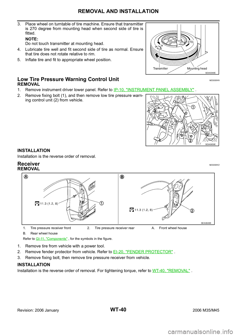
3. Place wheel on turntable of tire machine. Ensure that transmitter
is 270 degree from mounting head when second side of tire is
fitted.
NOTE:
Do not touch transmitter at mounting head.
4. Lubricate tire well and fit second side of tire as normal. Ensure
that tire does not rotate relative to rim.
5. Inflate tire and fit to appropriate wheel position.
Low Tire Pressure Warning Control UnitNES000KN
REMOVAL
1. Remove instrument driver lower panel. Refer to IP-10, "INSTRUMENT PANEL ASSEMBLY" .
2. Remove fixing bolt (1), and then remove low tire pressure warn-
ing control unit (2) from vehicle.
INSTALLATION
Installation is the reverse order of removal.
ReceiverNES000KO
REMOVAL
1. Remove tire from vehicle with a power tool.
2. Remove fender protector from vehicle. Refer to EI-20, "
FENDER PROTECTOR" .
3. Remove fixing bolt, then remove tire pressure receiver from vehicle.
INSTALLATION
Installation is the reverse order of removal. For tightening torque, refer to WT-40, "REMOVAL" .
SEIA0048E
SEIA0659E
1. Tire pressure receiver front 2. Tire pressure receiver rear A. Front wheel house
B. Rear wheel house
Refer to GI-11, "
Components" , for the symbols in the figure.
SEIA0649E