flat tire INFINITI M35 2006 Factory Service Manual
[x] Cancel search | Manufacturer: INFINITI, Model Year: 2006, Model line: M35, Model: INFINITI M35 2006Pages: 5621, PDF Size: 65.56 MB
Page 1514 of 5621
LANE DEPARTURE WARNING SYSTEM
DI-81
C
D
E
F
G
H
I
J
L
MA
B
DI
Revision: 2006 January2006 M35/M45
Camera Aiming AdjustmentNKS003VI
OUTLINE
Adjust the camera aiming every time the LDW camera unit is removed or installed.
CAUTION:
Place the vehicle on the level ground when the camera aiming adjustment is operated.
Follow the CONSULT-II when adjusting the camera aiming. (Camera aiming adjustment cannot be
operated without CONSULT-II.)
PREPARATION
Keep all tires inflated to correct pressures. Adjust the tire pressure to the specified pressure value.
There is no-load in vehicle. Check if coolant, engine oil are filled up to correct level and fuel tank is full.
Shift the gear into “P” position and release the parking brake.
Clean the windshield.
NOTE:
Do not place anything reflective on the upper surface of instrument panel.
TARGET SETTING
Preparation Aiming Adjustment Jig
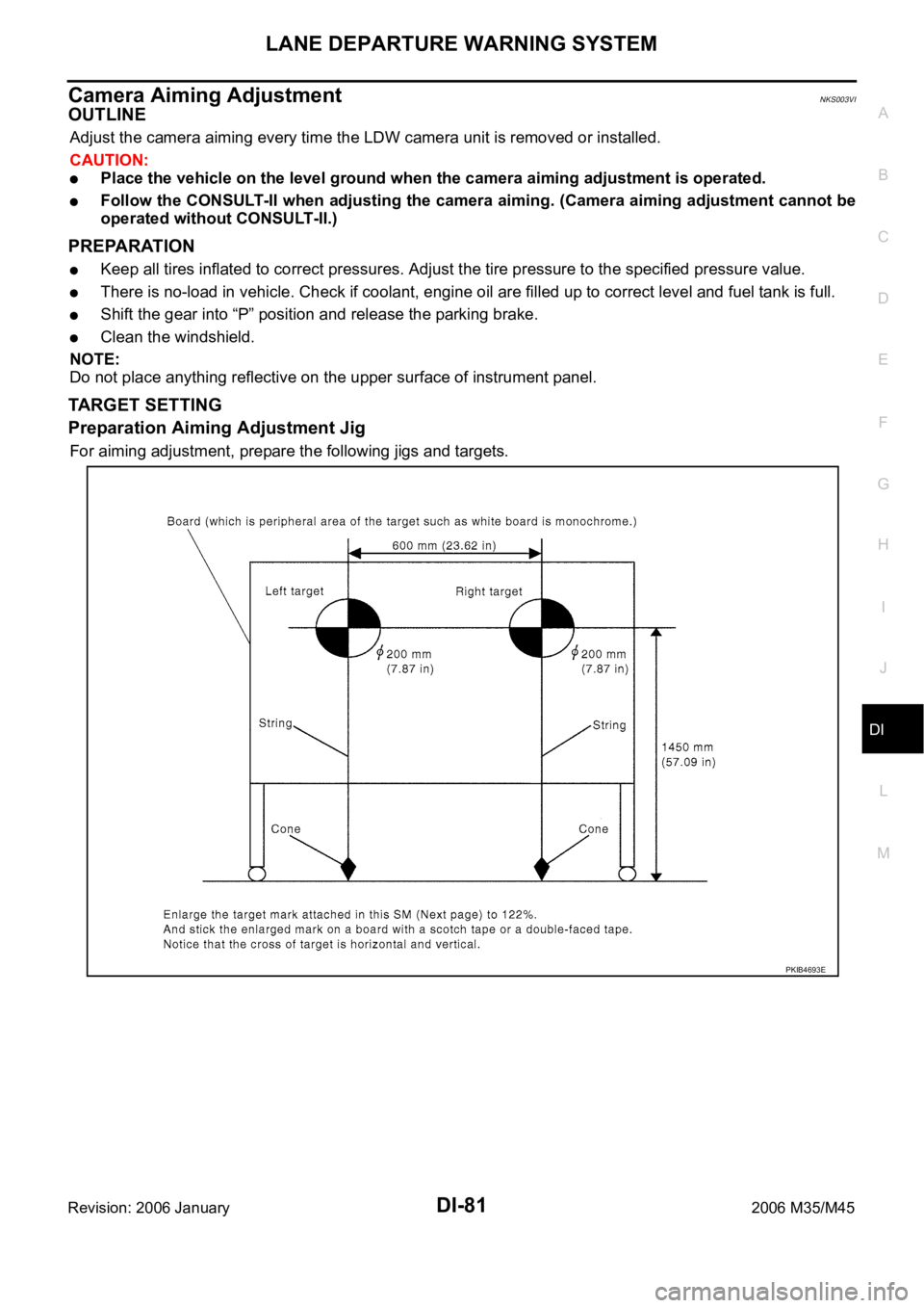
For aiming adjustment, prepare the following jigs and targets.
PKIB4693E
Page 4465 of 5621
LT-38
HEADLAMP (FOR USA) - CONVENTIONAL TYPE -
Revision: 2006 January2006 M35/M45
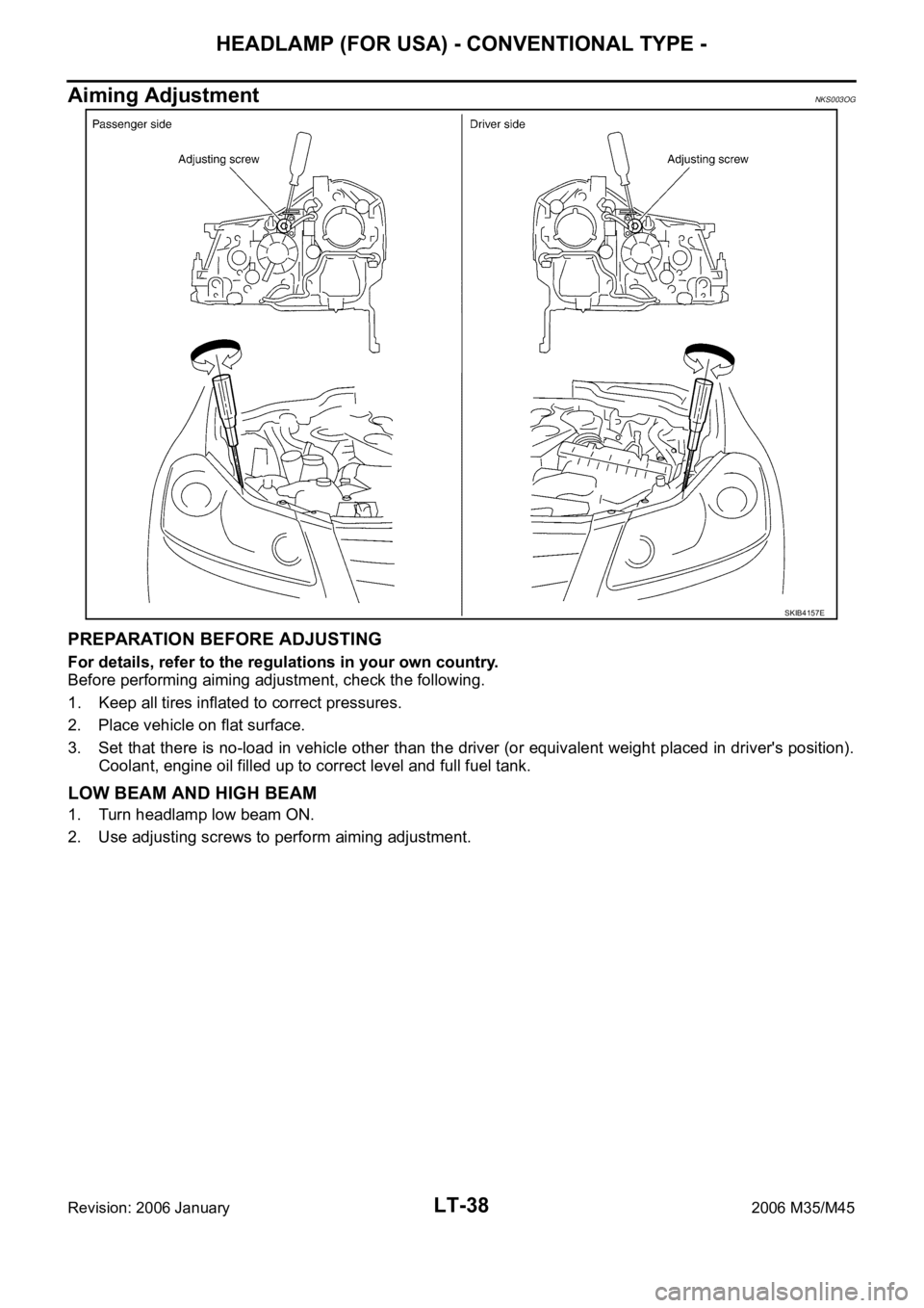
Aiming AdjustmentNKS003OG
PREPARATION BEFORE ADJUSTING
For details, refer to the regulations in your own country.
Before performing aiming adjustment, check the following.
1. Keep all tires inflated to correct pressures.
2. Place vehicle on flat surface.
3. Set that there is no-load in vehicle other than the driver (or equivalent weight placed in driver's position).
Coolant, engine oil filled up to correct level and full fuel tank.
LOW BEAM AND HIGH BEAM
1. Turn headlamp low beam ON.
2. Use adjusting screws to perform aiming adjustment.
SKIB4157E
Page 4501 of 5621
LT-74
HEADLAMP (FOR USA) - XENON TYPE -
Revision: 2006 January2006 M35/M45
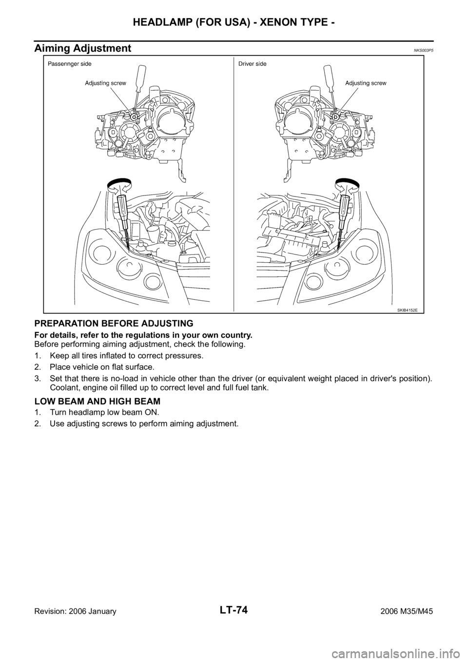
Aiming AdjustmentNKS003P5
PREPARATION BEFORE ADJUSTING
For details, refer to the regulations in your own country.
Before performing aiming adjustment, check the following.
1. Keep all tires inflated to correct pressures.
2. Place vehicle on flat surface.
3. Set that there is no-load in vehicle other than the driver (or equivalent weight placed in driver's position).
Coolant, engine oil filled up to correct level and full fuel tank.
LOW BEAM AND HIGH BEAM
1. Turn headlamp low beam ON.
2. Use adjusting screws to perform aiming adjustment.
SKIB4152E
Page 4636 of 5621
FRONT FOG LAMP
LT-209
C
D
E
F
G
H
I
J
L
MA
B
LT
Revision: 2006 January2006 M35/M45
3. CHECK CAN COMMUNICATIONS BETWEEN BCM AND IPDM E/R
Select “BCM” on CONSULT-II, and perform self-diagnosis for “BCM”.
Display of self-diagnosis results
NO DTC>> Replace IPDM E/R. Refer to PG-31, "Removal and
Installation of IPDM E/R" .
CAN COMM CIRCUIT>> Refer to BCS-15, "
CAN Communication
Inspection Using CONSULT-II (Self-Diagnosis)" .
Aiming AdjustmentNKS003RH
The fog lamp is a semi-sealed beam type which uses a replaceable halogen bulb. Before performing aiming
adjustment, make sure of the following.
Keep all tires inflated to correct pressure.
Place vehicle on level ground.
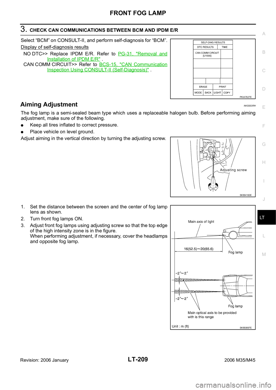
Adjust aiming in the vertical direction by turning the adjusting screw.
1. Set the distance between the screen and the center of fog lamp
lens as shown.
2. Turn front fog lamps ON.
3. Adjust front fog lamps using adjusting screw so that the top edge
of the high intensity zone is in the figure.
When performing adjustment, if necessary, cover the headlamps
and opposite fog lamp.
PKIA7627E
SKIB4160E
SKIB0897E
Page 4812 of 5621
CHASSIS AND BODY MAINTENANCE
MA-35
C
D
E
F
G
H
I
J
K
MA
B
MA
Revision: 2006 January2006 M35/M45
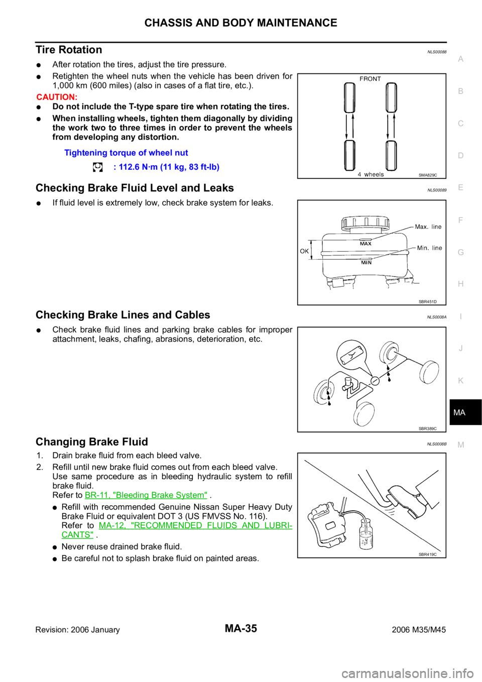
Tire RotationNLS00088
After rotation the tires, adjust the tire pressure.
Retighten the wheel nuts when the vehicle has been driven for
1,000 km (600 miles) (also in cases of a flat tire, etc.).
CAUTION:
Do not include the T-type spare tire when rotating the tires.
When installing wheels, tighten them diagonally by dividing
the work two to three times in order to prevent the wheels
from developing any distortion.
Checking Brake Fluid Level and LeaksNLS00089
If fluid level is extremely low, check brake system for leaks.
Checking Brake Lines and CablesNLS0008A
Check brake fluid lines and parking brake cables for improper
attachment, leaks, chafing, abrasions, deterioration, etc.
Changing Brake FluidNLS0008B
1. Drain brake fluid from each bleed valve.
2. Refill until new brake fluid comes out from each bleed valve.
Use same procedure as in bleeding hydraulic system to refill
brake fluid.
Refer to BR-11, "
Bleeding Brake System" .
Refill with recommended Genuine Nissan Super Heavy Duty
Brake Fluid or equivalent DOT 3 (US FMVSS No. 116).
Refer to MA-12, "
RECOMMENDED FLUIDS AND LUBRI-
CANTS" .
Never reuse drained brake fluid.
Be careful not to splash brake fluid on painted areas.Tightening torque of wheel nut
: 112.6 Nꞏm (11 kg, 83 ft-lb)
SMA829C
SBR451D
SBR389C
SBR419C
Page 4821 of 5621
PB-2
PARKING BRAKE SYSTEM
Revision: 2006 January2006 M35/M45
PARKING BRAKE SYSTEMPFP:36010
On-Vehicle ServiceNFS000PR
PEDAL STROKE
Operate parking brake pedal with a force of 196 N (20 kg, 44 lb), make sure pedal stroke is within the
specified number of notches. (Check it by listening and counting ratchet clicks.)
INSPECT COMPONENTS
Make sure that the mounting conditions (looseness, backlash, etc.) of each component are normal.
Check the following:
–Device assembly for bend, damage and cracks. Replace if there are.
–Cables and equalizer for wear and damage. Replace if there are.
–Parking brake switch. Replace if it does not work correctly.
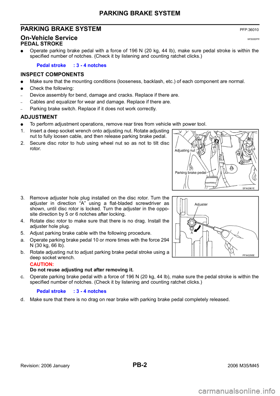
ADJUSTMENT
To perform adjustment operations, remove rear tires from vehicle with power tool.
1. Insert a deep socket wrench onto adjusting nut. Rotate adjusting
nut to fully loosen cable, and then release parking brake pedal.
2. Secure disc rotor to hub using wheel nut so as not to tilt disc
rotor.
3. Remove adjuster hole plug installed on the disc rotor. Turn the
adjuster in direction “A” using a flat-bladed screwdriver as
shown, until disc rotor is locked. Turn the adjuster in the oppo-
site direction by 5 or 6 notches after locking.
4. Rotate disc rotor to make sure that there is no drag. Install the
adjuster hole plug.
5. Adjust parking brake cable with the following procedure.
a. Operate parking brake pedal 10 or more times with the force 294
N (30 kg, 66 lb).
b. Rotate adjusting nut to adjust parking brake pedal stroke using a
deep socket wrench.
CAUTION:
Do not reuse adjusting nut after removing it.
c. Operate parking brake pedal with a force of 196 N (20 kg, 44 lb), make sure the pedal stroke is within the
specified number of notches. (Check it by listening and counting ratchet clicks.)
d. Make sure that there is no drag on rear brake with parking brake pedal completely released. Pedal stroke : 3 - 4 notches
SFIA2961E
Pedal stroke : 3 - 4 notches
PFIA0295E
Page 4825 of 5621
PB-6
PARKING BRAKE SHOE
Revision: 2006 January2006 M35/M45
Removal and InstallationNFS000PV
REMOVAL
WAR NING :
Clean brakes with a vacuum dust collector to minimize the hazard of air borne particles or other mate-
rials.
CAUTION:
Clean dust on disc rotor and back plate using a vacuum dust collector. Do not blow with com-
pressed air.
Put matching marks on both disc rotor and wheel hub when removing disc rotor.
1. Remove rear tires from vehicle with power tool.
2. Remove disc rotor with parking brake pedal completely in the released position. Refer to BR-31,
"Removal and Installation of Brake Caliper Assembly" .
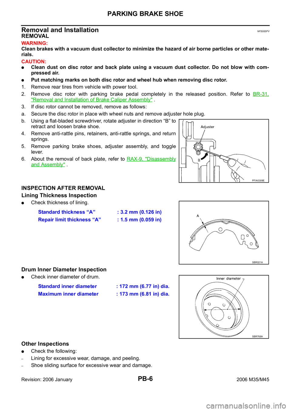
3. If disc rotor cannot be removed, remove as follows:
a. Secure the disc rotor in place with wheel nuts and remove adjuster hole plug.
b. Using a flat-bladed screwdriver, rotate adjuster in direction “B” to
retract and loosen brake shoe.
4. Remove anti-rattle pins, retainers, anti-rattle springs, and return
springs.
5. Remove parking brake shoes, adjuster assembly, and toggle
lever.
6. About the removal of back plate, refer to RAX-9, "
Disassembly
and Assembly" .
INSPECTION AFTER REMOVAL
Lining Thickness Inspection
Check thickness of lining.
Drum Inner Diameter Inspection
Check inner diameter of drum.
Other Inspections
Check the following:
–Lining for excessive wear, damage, and peeling.
–Shoe sliding surface for excessive wear and damage.
PFIA0309E
Standard thickness “A” : 3.2 mm (0.126 in)
Repair limit thickness “A” : 1.5 mm (0.059 in)
SBR021A
Standard inner diameter : 172 mm (6.77 in) dia.
Maximum inner diameter : 173 mm (6.81 in) dia.
SBR768A
Page 5364 of 5621

PRECAUTIONS
SRS-3
C
D
E
F
G
I
J
K
L
MA
B
SRS
Revision: 2006 January2006 M35/M45
PRECAUTIONSPFP:00001
Precautions for Supplemental Restraint System (SRS) “AIR BAG” and “SEAT
BELT PRE-TENSIONER”
NHS0008O
The Supplemental Restraint System such as “AIR BAG” and “SEAT BELT PRE-TENSIONER”, used along
with a front seat belt, helps to reduce the risk or severity of injury to the driver and front passenger for certain
types of collision. This system includes seat belt switch inputs and dual stage front air bag modules. The SRS
system uses the seat belt switches to determine the front air bag deployment, and may only deploy one front
air bag, depending on the severity of a collision and whether the front occupants are belted or unbelted.
Information necessary to service the system safely is included in the SRS and SB section of this Service Man-
ual.
WAR NING :
To avoid rendering the SRS inoperative, which could increase the risk of personal injury or death
in the event of a collision which would result in air bag inflation, all maintenance must be per-
formed by an authorized NISSAN/INFINITI dealer.
Improper maintenance, including incorrect removal and installation of the SRS, can lead to per-
sonal injury caused by unintentional activation of the system. For removal of Spiral Cable and Air
Bag Module, see the SRS section.
Do not use electrical test equipment on any circuit related to the SRS unless instructed to in this
Service Manual. SRS wiring harnesses can be identified by yellow and/or orange harnesses or
harness connectors.
Precautions for SRS “AIR BAG” and “SEAT BELT PRE-TENSIONER” ServiceNHS0008P
Do not use electrical test equipment to check SRS circuits unless instructed to in this Service Manual.
Before servicing the SRS, turn ignition switch OFF, disconnect both battery cables and wait at least 3 min-
utes.
For approximately 3 minutes after the cables are removed, it is still possible for the air bag and seat belt
pre-tensioner to deploy. Therefore, do not work on any SRS connectors or wires until at least 3 minutes
have passed.
Diagnosis sensor unit must always be installed with their arrow marks “” pointing towards the front of the
vehicle for proper operation. Also check diagnosis sensor unit for cracks, deformities or rust before instal-
lation and replace as required.
The spiral cable must be aligned with the neutral position since its rotations are limited. Do not turn steer-
ing wheel and column after removal of steering gear.
Handle air bag module carefully. Always place driver and front passenger air bag modules with the pad
side facing upward and seat mounted front side air bag module standing with the stud bolt side facing
down.
Conduct self-diagnosis to check entire SRS for proper function after replacing any components.
After air bag inflates, the front instrument panel assembly should be replaced if damaged.
Always replace instrument panel pad following front passenger air bag deployment.
Occupant Classification System PrecautionNHS0008Q
Replace occupant classification system control unit and passenger front seat cushion as an assembly.
Refer to SE-165, "
Passenger's Seat Components" .
Page 5411 of 5621

SRS-50
COLLISION DIAGNOSIS
Revision: 2006 January2006 M35/M45
COLLISION DIAGNOSISPFP:00015
For Frontal CollisionNHS0009L
To repair the SRS, perform the following steps.
When SRS (except the front side air bag and side curtain air bag modules) is activated in a collision:
1. Replace the diagnosis sensor unit.
2. Remove the air bag modules (except the front side air bag modules and side curtain air bag modules),
crash zone sensor assembly, bracket and seat belt pre-tensioner assemblies.
3. Check the SRS components using the table below:
–Replace any SRS components showing visible signs of damage (dents, cracks and deformation).
4. Install new air bag modules (except the front side air bag modules and side curtain air bag modules) crash
zone sensor assembly, bracket and seat belt pre-tensioner assemblies.
5. Conduct self-diagnosis using CONSULT-II or “AIR BAG” warning lamp. Refer to SRS-19, "
SRS Operation
Check" for details. Ensure entire SRS operates properly.
When SRS is not activated in a collision:
1. Check the SRS components using the table below:
–Replace any SRS components showing visible signs of damage (dents, cracks and deformation).
2. Conduct self-diagnosis using CONSULT-II or “AIR BAG” warning lamp. Refer to SRS-19, "
SRS Operation
Check" for details. Ensure entire SRS operates properly.
When only one front air bag module is activated in a collision:
1. Replace the following components:
–Diagnosis sensor unit
–Crash zone sensor
–Activated front air bag and seat belt pre-tensioner.
2. Check the other SRS components using the table below (Refer to “SRS is NOT activated”).
–Replace any SRS components showing visible signs of damage (dents, cracks and deformation).
3. Conduct self-diagnosis using CONSULT-II or “AIR BAG” warning lamp. Refer to SRS-19, "
SRS Operation
Check" for details. Ensure entire SRS operates properly.
Only one front air bag may inflate a crash, depending on the crash severity and whether the front occupants
are belted or unbelted. This does not indicate improper performance of the system. Perform self-diagnosis to
make sure the entire SRS operates properly.
SRS INSPECTION (FOR FRONTAL COLLISION)
Part SRS is activated SRS is NOT activated
Driver airbag
moduleIf the Driver airbag has deployed:
REPLACE.
Install with new fasteners.If the Driver air bag has NOT been activated:
[same text as in current manual]
Passenger front
airbag moduleIf the Passenger front airbag has deployed:
REPLACE.
Install with new fasteners.If the Passenger front air bag has NOT been activated:
[same text as in current manual]
Crash zone
sensorIf any of the front airbags or seat belt pre-
tensionsers have been activated:
REPLACE the crash zone sensor and bracket
with new fasteners. If the front airbags or seat belt pre-tensionsers have NOT
been activated:
[same text as in current manual]
Seat belt pre-ten-
sioner assembliesIf the driver or passenger Seat belt pre-ten-
sioner has been activated:
REPLACE the seat belt pre-tensioner
assemblies with new fasteners. If the pre-tensioners have NOT been activated:
[same text as in current manual]
Diagnosis sensor
unitIf any of the SRS components have been
activated:
REPLACE the Diagnosis sensor unit.
Install with new fasteners.If none of the SRS components have been activated:
[same text as in current manual]
Page 5531 of 5621
WT-6
ROAD WHEEL
Revision: 2006 January2006 M35/M45
ROAD WHEELPFP:40300
InspectionNES000JO
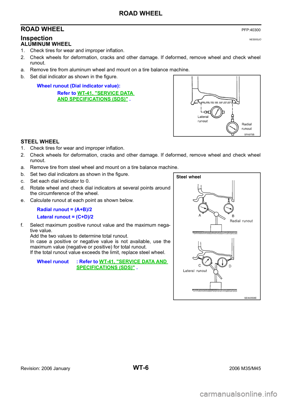
ALUMINUM WHEEL
1. Check tires for wear and improper inflation.
2. Check wheels for deformation, cracks and other damage. If deformed, remove wheel and check wheel
runout.
a. Remove tire from aluminum wheel and mount on a tire balance machine.
b. Set dial indicator as shown in the figure.
STEEL WHEEL
1. Check tires for wear and improper inflation.
2. Check wheels for deformation, cracks and other damage. If deformed, remove wheel and check wheel
runout.
a. Remove tire from steel wheel and mount on a tire balance machine.
b. Set two dial indicators as shown in the figure.
c. Set each dial indicator to 0.
d. Rotate wheel and check dial indicators at several points around
the circumference of the wheel.
e. Calculate runout at each point as shown below.
f. Select maximum positive runout value and the maximum nega-
tive value.
Add the two values to determine total runout.
In case a positive or negative value is not available, use the
maximum value (negative or positive) for total runout.
If the total runout value exceeds the limit, replace steel wheel. Wheel runout (Dial indicator value):
Refer to WT-41, "
SERVICE DATA
AND SPECIFICATIONS (SDS)" .
SFA975B
Radial runout = (A+B)/2
Lateral runout = (C+D)/2
Wheel runout : Refer to WT-41, "
SERVICE DATA AND
SPECIFICATIONS (SDS)" .
SEIA0558E