Oil INFINITI M35 2006 Factory Service Manual
[x] Cancel search | Manufacturer: INFINITI, Model Year: 2006, Model line: M35, Model: INFINITI M35 2006Pages: 5621, PDF Size: 65.56 MB
Page 3471 of 5621
GI-8
PRECAUTIONS
Revision: 2006 January2006 M35/M45
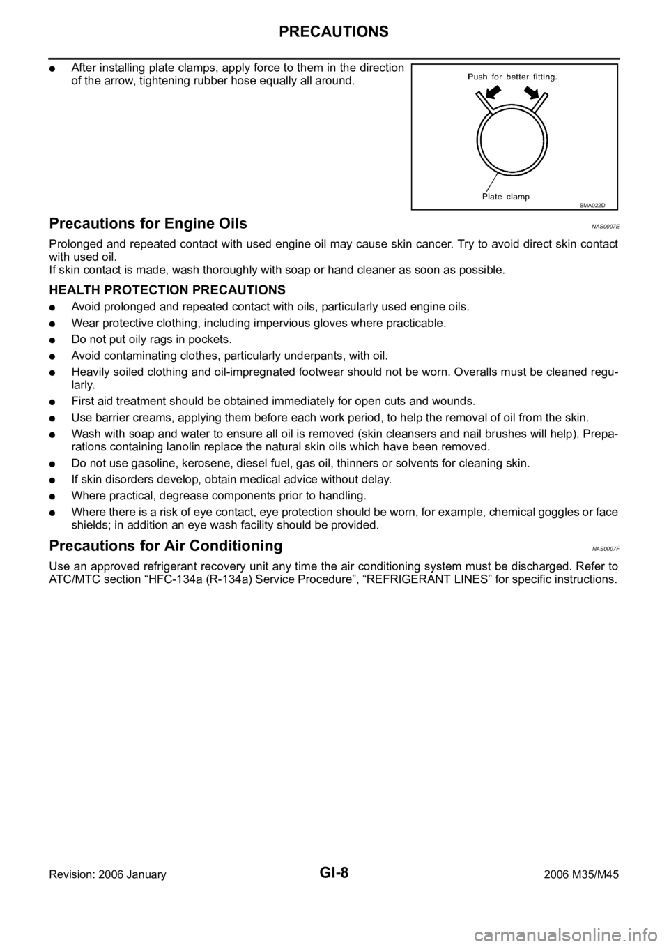
After installing plate clamps, apply force to them in the direction
of the arrow, tightening rubber hose equally all around.
Precautions for Engine OilsNAS0007E
Prolonged and repeated contact with used engine oil may cause skin cancer. Try to avoid direct skin contact
with used oil.
If skin contact is made, wash thoroughly with soap or hand cleaner as soon as possible.
HEALTH PROTECTION PRECAUTIONS
Avoid prolonged and repeated contact with oils, particularly used engine oils.
Wear protective clothing, including impervious gloves where practicable.
Do not put oily rags in pockets.
Avoid contaminating clothes, particularly underpants, with oil.
Heavily soiled clothing and oil-impregnated footwear should not be worn. Overalls must be cleaned regu-
larly.
First aid treatment should be obtained immediately for open cuts and wounds.
Use barrier creams, applying them before each work period, to help the removal of oil from the skin.
Wash with soap and water to ensure all oil is removed (skin cleansers and nail brushes will help). Prepa-
rations containing lanolin replace the natural skin oils which have been removed.
Do not use gasoline, kerosene, diesel fuel, gas oil, thinners or solvents for cleaning skin.
If skin disorders develop, obtain medical advice without delay.
Where practical, degrease components prior to handling.
Where there is a risk of eye contact, eye protection should be worn, for example, chemical goggles or face
shields; in addition an eye wash facility should be provided.
Precautions for Air Conditioning NAS0007F
Use an approved refrigerant recovery unit any time the air conditioning system must be discharged. Refer to
ATC/MTC section “HFC-134a (R-134a) Service Procedure”, “REFRIGERANT LINES” for specific instructions.
SMA022D
Page 3500 of 5621

SERVICE INFORMATION FOR ELECTRICAL INCIDENT
GI-37
C
D
E
F
G
H
I
J
K
L
MB
GI
Revision: 2006 January2006 M35/M45
Do not apply excessive shock to the control unit by dropping or
hitting it.
Be careful to prevent condensation in the control unit due to
rapid temperature changes and do not let water or rain get on it.
If water is found in the control unit, dry it fully and then install it in
the vehicle.
Be careful not to let oil to get on the control unit connector.
Avoid cleaning the control unit with volatile oil.
Do not disassemble the control unit, and do not remove the
upper and lower covers.
When using a DMM, be careful not to let test probes get close to
each other to prevent the power transistor in the control unit
from damaging battery voltage because of short circuiting.
When checking input and output signals of the control unit, use
the specified check adapter.
SAIA0255E
SEF348N
Page 3505 of 5621
GI-42
LIFTING POINT
Revision: 2006 January2006 M35/M45
LIFTING POINTPFP:00000
Special Service Tools NAS0007Y
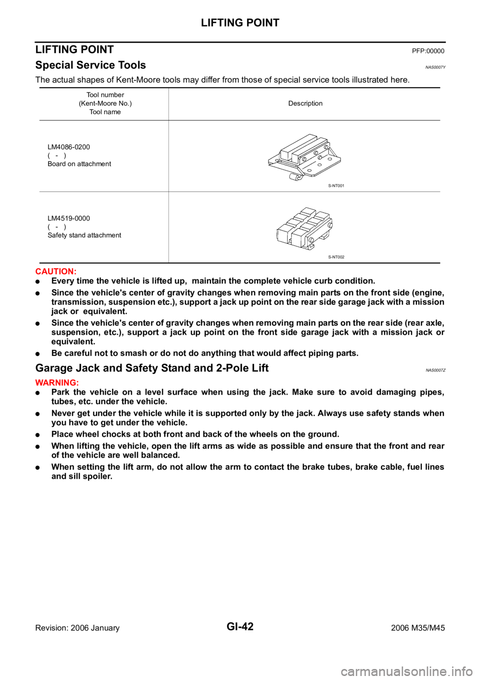
The actual shapes of Kent-Moore tools may differ from those of special service tools illustrated here.
CAUTION:
Every time the vehicle is lifted up, maintain the complete vehicle curb condition.
Since the vehicle's center of gravity changes when removing main parts on the front side (engine,
transmission, suspension etc.), support a jack up point on the rear side garage jack with a mission
jack or equivalent.
Since the vehicle's center of gravity changes when removing main parts on the rear side (rear axle,
suspension, etc.), support a jack up point on the front side garage jack with a mission jack or
equivalent.
Be careful not to smash or do not do anything that would affect piping parts.
Garage Jack and Safety Stand and 2-Pole LiftNAS0007Z
WAR NING :
Park the vehicle on a level surface when using the jack. Make sure to avoid damaging pipes,
tubes, etc. under the vehicle.
Never get under the vehicle while it is supported only by the jack. Always use safety stands when
you have to get under the vehicle.
Place wheel chocks at both front and back of the wheels on the ground.
When lifting the vehicle, open the lift arms as wide as possible and ensure that the front and rear
of the vehicle are well balanced.
When setting the lift arm, do not allow the arm to contact the brake tubes, brake cable, fuel lines
and sill spoiler.
Tool number
(Kent-Moore No.)
Tool nameDescription
LM4086-0200
( - )
Board on attachment
LM4519-0000
( - )
Safety stand attachment
S-NT001
S-NT002
Page 3613 of 5621

GW-94
REAR WINDOW DEFOGGER
Revision: 2006 January2006 M35/M45
Filament CheckNIS0022Y
1. When measuring voltage, wrap tin foil around the top of the neg-
ative probe. Then press the foil against the wire with your finger.
2. Attach probe circuit tester (in Volt range) to middle portion of
each filament.
3. If a filament is burned out, circuit tester registers 0 or battery
voltage.
4. To locate burned out point, move probe to left and right along fil-
ament. Test needle will swing abruptly when probe passes the
point.
Filament RepairNIS0022Z
REPAIR EQUIPMENT
Conductive silver composition (Dupont No. 4817 or equivalent)
Ruler 30 cm (11.8 in) long
Drawing pen
Heat gun
Alcohol
Cloth
SEL122R
SEL263
SEL265
Page 3643 of 5621
IDX-2
ALPHABETICAL INDEX
A
A/C air flow ...................................................... ATC-37
A/C component layout ..................................... ATC-25
A/C compressor mounting ........... ATC-155, ATC-158,
ATC-159
, ATC-160, ATC-162, ATC-164, ATC-165,
ATC-167
, ATC-168, ATC-169
A/C compressor precaution ............................. ATC-12
A/C compressor special service tool ................ ATC-16
A/C control operation (auto A/C) ...................... ATC-33
A/C diagnostic work flow (auto A/C) .............. ATC-111
A/C evaporator ............................................... ATC-168
A/C HFC134a (R134a) system precaution ........ ATC-6
A/C HFC134a (R134a) system service procedure .......
ATC-151
A/C HFC134a (R134a) system service tools ... ATC-17
A/C HFC134a system service equipment precaution ...
ATC-13
A/C lubricant (R134a) ...................................... ATC-26
A/C lubrication oil ........................................... ATC-174
A/C operational check ...................................... ATC-64
A/C self-diagnoses (auto A/C) ........ ATC-55, ATC-111
A/C service data specification ........................ ATC-174
A/C system description (auto A/C) ................... ATC-29
A/C trouble diagnoses (auto A/C) .................... ATC-40
A/C, A - Wiring diagram ................................... ATC-46
A/T fluid checking ...................... AT-13, AT-53, MA-29
A/T fluid cooler cleaning .................................... AT-14
A/T fluid replacement ............................. AT-12, MA-31
A/T fluid temperature sensor ........................... AT-135
A/T IND - Wiring diagram .................................... DI-57
A/T self-diagnoses ............................... AT-92, AT-103
A/T shift lock system ........................................ AT-229
A/T shift lock system - Wiring diagram ............ AT-230
A/T trouble diagnoses ........................................ AT-44
Accelerator control system ............................... ACC-3
Accelerator pedal position (APP) sensor ........ EC-626,
EC-633
, EC-647, EC-1358, EC-1365, EC-1379
Accelerator pedal released position learning .... EC-95,
EC-806
AF1B1-Wiring diagram ...... EC-249, EC-258, EC-267,
EC-277
, EC-657, EC-972, EC-981, EC-990, EC-1000,
EC-1389
AF1B2-Wiring diagram ...... EC-251, EC-260, EC-269,
EC-279
, EC-659, EC-974, EC-983, EC-992, EC-1002,
EC-1391
AF1HB1-Wiring diagram .................... EC-183, EC-905
AF1HB2-Wiring diagram .................... EC-185, EC-907
Air bag .............................................................. SRS-3
Air bag precautions ........................................... SRS-3
Air cleaner and air duct(VK45DE) ................... EM-177
Air cleaner and air duct(VQ35DE) .................... EM-17
Air cleaner filter replacement ............................ MA-25
Air cleaner filter replacement(VQ35DE) ........... MA-18
Air cleaner filter(VQ35DE) ................................ EM-18
Air conditioner cut control .................... EC-35, EC-745
Air flow meter - See Mass air flow sensor ...... EC-205,
EC-214
, EC-927, EC-936
Air fuel ratio sensor 1 ......... EC-246, EC-256, EC-265, EC-274
, EC-655, EC-969, EC-979, EC-988, EC-997,
EC-1387
Air fuel ratio sensor 1 heater ............. EC-182, EC-904
Air mix. door motor ......................... ATC-83, ATC-141
Alternator ........................................................... SC-23
Ambient sensor ............................. ATC-113, ATC-126
Angular tightening application ............................. EM-6
Angular tightening application(VK45DE) ........ EM-164
APPS1 - Wiring diagram ................. EC-628, EC-1360
APPS2 - Wiring diagram ................. EC-635, EC-1367
APPS3 - Wiring diagram ................. EC-649, EC-1381
ASC/BS - Wiring diagram ............... EC-587, EC-1313
ASC/SW - Wiring diagram .............. EC-570, EC-1296
ASCBOF - Wiring diagram .............. EC-708, EC-1450
ASCD .................................................. EC-36, EC-746
ASCD (automatic speed control device) ........... ACS-3
ASCIND - Wiring diagram ............... EC-715, EC-1457
AT indicator lamp ................................................ DI-56
Auto air conditioner - Wiring diagram ............. ATC-46
Auto amp ...................................................... ATC-125
Auto anti-dazzling inside mirror .......... GW-71, GW-72
Automatic amplifier ........... ATC-53, ATC-66, ATC-125
Automatic transmission fluid replacement ........ MA-32
AWD - Wiring diagram ....................................... TF-17
Axle ................................................................... MA-37
B
Back-up lamp ................................................... LT-246
Basic inspection .................................. EC-77, EC-788
Battery ................................................................. SC-4
Battery current sensor ....... EC-537, EC-543, EC-549,
EC-555
, EC-1263, EC-1269, EC-1275, EC-1281
Battery/Starting/Charging System Tester .......... SC-28
Battery/Starting/Charging System Tester(Battery) SC-7
Battery/Starting/Charging System Tester(Starting
system) .............................................................. SC-13
BCM (Body control module) .............................. BCS-3
Block heater(VK45DE) .................................... EM-249
Block heater(VQ35DE) ................................... EM-123
Blower motor ................................... ATC-89, ATC-132
Blower unit .................................................... ATC-130
Brake fluid level ................................................ MA-35
Brake hydraulic line ........................................... BR-12
Brake inspection ............................................... MA-36
Brake lines and cables inspection .................... MA-35
Brake pedal .......................................................... BR-6
Brake switch ................................... EC-598, EC-1329
BRK/SW - Wiring diagram .............. EC-600, EC-1331
Bulb specifications ........................................... LT-315
Bumper, front ...................................................... EI-11
Bumper, rear ....................................................... EI-14
C
Camshaft inspection(VK45DE) ....................... EM-216
Camshaft inspection(VQ35DE) ......................... EM-86
Camshaft position sensor (PHASE) EC-383, EC-1106
Camshaft(VK45DE) ........................................ EM-215
Page 3645 of 5621

IDX-4
ALPHABETICAL INDEX
Electronic ignition (EI) system ............. EC-33, EC-743
Engine control module (ECM) .......... EC-496, EC-1215
Engine control system diagram ........... EC-30, EC-740
Engine coolant temperature sensor (ECTS) ... EC-226,
EC-238
, EC-948, EC-961
Engine coolant(VK45DE) .................................. CO-40
Engine coolant(VQ35DE) ................................. CO-11
Engine oil filter replacement ............................. MA-26
Engine oil filter replacement(VQ35DE) ............. MA-19
Engine oil precautions .......................................... GI-8
Engine oil replacement(VQ35DE) ..................... MA-18
Engine oil(VK45DE) ........................................... LU-26
Engine oil(VQ35DE) ............................................ LU-7
Engine removal(VK45DE) ............................... EM-244
Engine removal(VQ35DE) .............................. EM-113
Engine room cover ............................................ EM-14
Engine room cover(VK45DE) ......................... EM-173
ETC1 - Wiring diagram .................... EC-614, EC-1345
ETC2 - Wiring diagram .................... EC-609, EC-1340
ETC3 - Wiring diagram .................... EC-620, EC-1352
EVAP canister ...................................... EC-42, EC-752
EVAP canister purge volume control solenoid valve ....
EC-412
, EC-420, EC-1132, EC-1140
EVAP canister vent control valve ...... EC-427, EC-434,
EC-1147
, EC-1154
EVAP control system (small leak) diagnosis .. EC-403,
EC-466
, EC-1124, EC-1185
EVAP control system pressure sensor ........... EC-440,
EC-443
, EC-450, EC-1160, EC-1163, EC-1170
EVAP control system purge flow monitoring diagnosis
EC-398
, EC-1119
EVAP vapor lines inspection ................. MA-21, MA-28
Evaporative emission (EVAP) system . EC-39, EC-749
Evaporator ..................................................... ATC-168
Exhaust manifold(VK45DE) ............................ EM-183
Exhaust system ................................................... EX-3
Exhaust system inspection ..................... EX-3, MA-29
Expansion valve ............................................. ATC-169
F
F/FOG - Wiring diagram ................................... LT-197
F/PUMP - Wiring diagram ................ EC-686, EC-1428
Final drive pre-inspection .................. FFD-16, RFD-19
Final drive removal and installation .. FFD-13, RFD-16
Floor trim ............................................................. EI-50
Flow charts ......................................................... GI-28
Fluid temperature sensor (A/T) ........................ AT-135
Fluorescent leak detector .............................. ATC-170
FPCM - Wiring diagram ................... EC-527, EC-1253
Freeze frame data ............................... EC-59, EC-770
Front brake solenoid valve ................. AT-151, AT-153
Front bumper ...................................................... EI-11
Front combination lamp removal and installation LT-76
Front door ............................. BL-190, BL-196, GW-63
Front passenger air bag .................................. SRS-42
Front seat belt .................................................... SB-30
Front seat belt pre-tensioner ..... SB-2, SRS-3, SRS-47
Front washer ...................................................... WW-4
Front wiper ......................................................... WW-4
FTS - Wiring diagram ....................................... AT-136
FTTS - Wiring diagram .... EC-345, EC-350, EC-1068,
EC-1073
Fuel cut control (at no load high engine speed) EC-34,
EC-744
Fuel filter replacement ......................................... FL-4
Fuel gauge ............................................................ DI-5
Fuel injection system (Bank 1) ......... EC-321, EC-332,
EC-1044
, EC-1055
Fuel injection system (Bank 2) ......... EC-321, EC-332,
EC-1044
, EC-1055
Fuel injector ................................................... EC-1420
Fuel injector and fuel tube(VK45DE) .............. EM-193
Fuel injector and fuel tube(VQ35DE) ................ EM-45
Fuel level sensor EC-475, EC-477, EC-479, EC-1194,
EC-1196
, EC-1198
Fuel line inspection .................................. FL-3, MA-25
Fuel line inspection(VQ35DE) .......................... MA-18
Fuel precautions ................................................... GI-6
Fuel pressure check ........................... EC-98, EC-809
Fuel pressure release ......................... EC-98, EC-809
Fuel pump ....................................... EC-685, EC-1427
Fuel pump and gauge .......................................... FL-4
Fuel pump control module .............. EC-525, EC-1251
Fuel pump dropping resistor ........... EC-525, EC-1251
Fuel system ......................................................... FL-3
Fuel tank ............................................................ FL-10
Fuel tank temperature sensor .......... EC-343, EC-349,
EC-1066
, EC-1072
Fuel tank vacuum relief valve ............. EC-42, EC-752
FUELB1 - Wiring diagram EC-323, EC-334, EC-1046,
EC-1057
FUELB2 - Wiring diagram EC-325, EC-336, EC-1048,
EC-1059
Fuse .................................................................. PG-17
Fuse and fusible link box ................................ PG-112
Fusible link ........................................................ PG-17
G
Gauges ................................................................. DI-5
Generator ........................................................... SC-23
Generator - See Alternator ................................ SC-23
Glass ........................ GW-11, GW-61, GW-63, GW-67
Grille - See Exterior ............................................ EI-16
Ground distribution ........................................... PG-46
H
H/LAMP - Wiring diagram ....................... LT-13
, LT-48
Harness connector .......................................... PG-102
Harness layout .................................................. PG-63
Hazard warning lamp ....................................... LT-211
Headlamp removal and installation .................... LT-76
Headlining - See Roof trim .................................. EI-52
Heated oxygen sensor 2 (bank 1) .... EC-286, EC-297,
EC-310
, EC-1009, EC-1020, EC-1033
Heated oxygen sensor 2 (bank 2) .... EC-286, EC-297,
Page 3646 of 5621
IDX-5
A
C
D
E
F
G
H
I
J
K
L B
IDX
ALPHABETICAL INDEX
EC-310, EC-1009, EC-1020, EC-1033
Heated oxygen sensor 2 heater (bank 1) ....... EC-189,
EC-911
Heated oxygen sensor 2 heater (bank 2) ....... EC-189,
EC-911
Heated seat ..................................................... SE-143
Heater and cooling unit (Heater core) ........... ATC-135
HFC134a (R134a) system precaution ............... ATC-6
HFC134a (R134a) system service procedure ATC-151
HFC134a (R134a) system service tools .......... ATC-17
HFC134a system service equipment precaution ..........
ATC-13
High and low reverse clutch solenoid valve .... AT-159,
AT-161
Hood ................................................................... BL-15
Horn ................................................................. WW-53
HORN - Wiring diagram ................................... WW-53
How to erase DTC for OBD system ..... EC-67, EC-778
HSEAT - Wiring diagram ................................. SE-146
I
IATS - Wiring diagram ....................... EC-223
, EC-945
ICC - Wiring diagram ....................................... ACS-21
ICC/BS - Wiring diagram ................. EC-578, EC-1304
ICC/SW - Wiring diagram ................ EC-563, EC-1289
ICCBOF - Wiring diagram ................ EC-700, EC-1442
Idle air volume learning ....................... EC-96, EC-807
Idle mixture ratio .................................. EC-84, EC-795
Idle speed .............................. EC-77, EC-788, EC-793
Idle speed control (ISC) .... EC-483, EC-485, EC-1202,
EC-1204
Ignition coil ....................................... EC-666, EC-1407
Ignition coil(VK45DE) ...................................... EM-190
Ignition coil(VQ35DE) ........................................ EM-42
Ignition control system ..................... EC-666, EC-1407
Ignition timing ........................ EC-77, EC-788, EC-793
IGNSYS - Wiring diagram ................ EC-667, EC-1408
Illumination ....................................................... LT-295
Illumination control ................. LT-291, LT-292, LT-293
In vehicle sensor ........................... ATC-116, ATC-127
INJECT - Wiring diagram ................. EC-680, EC-1421
Injector ............................................................. EC-679
Input clutch solenoid valve ................. AT-147, AT-149
Instrument panel .................................................. IP-10
Intake air temperature sensor ........... EC-221, EC-241,
EC-943
, EC-964
Intake door control linkage adjustment ............ ATC-88
Intake door motor ........................... ATC-86, ATC-133
Intake manifold collector(VQ35DE) ................... EM-19
Intake manifold(VK45DE) ................................ EM-179
Intake manifold(VQ35DE) .................................. EM-24
Intake sensor ................................ ATC-122, ATC-129
Intake valve timing control (Bank 1) .. EC-178, EC-891
Intake valve timing control (Bank 2) .. EC-178, EC-891
Intake valve timing control position sensor (Bank 1) ....
EC-1228
Intake valve timing control position sensor (Bank 2) ....
EC-1228
Intake valve timing control solenoid valve (Bank 1) ......
EC-197
, EC-920
Intake valve timing control solenoid valve (Bank 2) ......
EC-197
, EC-920
Integrated homelink transmitter ....................... BL-281
Intelligent cruise control (ICC) system .............. ACS-6
Interior ................................................................. EI-37
Interior lamp ...................................................... LT-267
IPDM (Intelligent power distribution module engine
room) ................................................................. PG-18
IVCB1 - Wiring diagram ..................... EC-198, EC-921
IVCB2 - Wiring diagram ..................... EC-200, EC-923
IVCSB1 - Wiring diagram ............................... EC-1229
IVCSB2 - Wiring diagram ............................... EC-1231
IVIS (Infiniti vehicle immobilizer system) precautions ...
GI-3
IVTB1 - Wiring diagram ................................... EC-894
IVTB2 - Wiring diagram ................................... EC-896
K
Knock sensor (KS) ........................... EC-371
, EC-1094
KS - Wiring diagram ......................... EC-372, EC-1095
L
LAN system circuit ........................................... ATC-70
Lane Departure Warning System ....................... DI-78
Laser beam aiming adjustment ....................... ACS-13
Latch (lower anchors and tether for children) system ...
SB-36
LDW .................................................................... DI-78
LDW - Wiring Diagram ........................................ DI-89
License lamp ..................................................... LT-249
Line pressure solenoid valve ........................... AT-130
Line pressure test (A/T) ..................................... AT-55
Liquid gasket application ......................... EM-7, LU-22
Liquid gasket application(VQ35DE) ........... LU-3, CO-3
Location of electrical units ................................. PG-96
Low coast brake solenoid valve ......... AT-163, AT-165
Low tire pressure warning system ...................... WT-9
Lubricant (R134a) A/C ..................................... ATC-26
Lubrication circuit (engine)(VK45DE) ................ LU-24
Lubrication circuit (engine)(VQ35DE) .................. LU-5
Lubrication oil A/C .......................................... ATC-174
M
MAFS - Wiring diagram ..... EC-208
, EC-216, EC-930,
EC-938
Magnet clutch .................................................. ATC-94
MAIN - Wiring diagram ........ EC-166, EC-879, AT-180
Maintenance (engine)(VQ35DE) ...................... MA-14
Major overhaul (Final drive) .............. FFD-15, RFD-18
Major overhaul (Transfer) .................................. TF-45
Malfunction indicator lamp (MIL) .......... EC-69, EC-780
Manual mode switch ........................................ AT-167
Mass air flow sensor (MAFS) ............ EC-205, EC-214,
EC-927
, EC-936
Page 3647 of 5621
IDX-6
ALPHABETICAL INDEX
Meter ..................................................................... DI-5
METER - Wiring diagram .................................... DI-13
MIL data link connectors circuit ....... EC-722, EC-1459
MIL/DL - Wiring diagram .................. EC-722, EC-1459
MIRROR - Wiring diagram ................................ GW-99
Mirror, door ..................................................... GW-120
Mirror, out side ................................................ GW-120
Misfire .............................................. EC-361, EC-1084
MMSW - Wiring diagram .................................. AT-168
Mode door control linkage adjustment ATC-79, ATC-82
Mode door motor .............. ATC-75, ATC-80, ATC-140
Molding - See Exterior .............................. EI-25, EI-29
Mud guard - See Exterior .................................... EI-22
Multiport fuel injection (MFI) system .... EC-31, EC-741
Multiport fuel injection precautions ....................... GI-7
N
NATS - Wiring diagram .................................... BL-256
NONDTC - Wiring diagram .............................. AT-187
NVH troubleshooting (EM) .............................. EM-171
NVH troubleshooting (EM)(VQ35DE) ............... EM-12
NVH troubleshooting (Final drive) ......... FFD-6, RFD-7
NVH troubleshooting (Propeller shaft) ................. PR-3
NVH troubleshooting (Transfer) ........................... TF-8
NVIS (Nissan vehicle immobilizer system) precautions
GI-3
O
O2H2B1 - Wiring diagram .................. EC-191
, EC-913
O2H2B2 - Wiring diagram .................. EC-193, EC-915
O2S2B1 - Wiring diagram .. EC-289, EC-300, EC-313,
EC-1012
, EC-1023, EC-1036
O2S2B2 - Wiring diagram .. EC-291, EC-302, EC-315,
EC-1014
, EC-1025, EC-1038
Oil cooler (engine)(VQ35DE) ............................. LU-14
Oil filter(VK45DE) .............................................. LU-29
Oil filter(VQ35DE) .............................................. LU-10
Oil pan (engine)(VK45DE) .............................. EM-187
Oil pan (engine)(VQ35DE) ................................ EM-29
Oil pressure (engine)(VK45DE) ......................... LU-26
Oil pressure (engine)(VQ35DE) ........................... LU-8
Oil pressure relief valve (engine)(VQ35DE) ........ LU-6
Oil pump (A/T) ................................................. AT-318
Oil pump (engine)(VK45DE) .............................. LU-30
Oil pump (engine)(VQ35DE) .............................. LU-18
Oil pump regulator valve (engine)(VK45DE) ..... LU-30
Oil pump regulator valve (engine)(VQ35DE) ..... LU-18
Oil seal replacement (engine)(VK45DE) ......... EM-229
Oil seal replacement (engine)(VQ35DE) .......... EM-98
Oil seal replacement (front of final drive) .......... FFD-9,
RFD-10
Oil seal replacement (side of final drive) ......... FFD-11,
RFD-14
On board diagnostic system ................ EC-54, EC-764
ORVR (On-board Refueling Vapor Recovery) .. EC-46,
EC-756
Out side mirror ................................................ GW-120
Overheat ......................................... EC-512, EC-1239
P
P/SCKT - Wiring diagram ................................ WW-51
Park/Neutral position switch ........... EC-504, EC-1223
Park/neutral position switch (A/T) .................... AT-113
Parking brake control ........................................... PB-3
Parking lamp .................................................... LT-249
PCV (positive crankcase ventilation) .. EC-51, EC-761
PGC/V - Wiring diagram .. EC-414, EC-422, EC-1134,
EC-1142
PHASE - Wiring diagram ............................... EC-1108
PHSB1 - Wiring diagram .................................. EC-385
PHSB2 - Wiring diagram .................................. EC-387
Pilot bushing replacement - See Pilot
converter(VQ35DE) ........................................ EM-124
Piston assembly(VK45DE) ............................. EM-260
Piston assembly(VQ35DE) ............................. EM-135
Piston pin inspection(VK45DE) ....................... EM-266
Piston pin inspection(VQ35DE) ...................... EM-140
Piston ring inspection(VK45DE) ..................... EM-267
Piston ring inspection(VQ35DE) ..................... EM-141
Piston to bore clearance(VK45DE) ................. EM-270
Piston to bore clearance(VQ35DE) ................ EM-144
PNP/SW - Wiring diagram . EC-506, EC-1225, AT-114
POS - Wiring diagram ..................... EC-378, EC-1101
POWER - Wiring diagram ................................... PG-5
Power door mirror .............................................. BL-24
Power socket ................................................... WW-51
Power steering fluid level ........................ PS-8, MA-37
Power steering gear ........................................... PS-18
Power steering hydraulic pressure .................... PS-29
Power steering oil pump .................................... PS-29
Power steering system bleeding .......................... PS-8
Power supply routing .......................................... PG-3
Power window .................................................. GW-13
PRE/SE - Wiring diagram EC-445, EC-452, EC-1165,
EC-1172
Precations for Leak detection dye .................. ATC-15
Precautions (General) ........................................... GI-4
Pressure switch 1 .............................. AT-153, AT-172
Pressure switch 2 ............................................ AT-165
Pressure switch 3 .............................. AT-149, AT-174
Pressure switch 5 .............................. AT-157, AT-176
Pressure switch 6 .............................. AT-161, AT-178
Pressure test (A/T) ............................................. AT-55
Propeller shaft ........................................... PR-4, PR-6
Propeller shaft on vehicle service ............. PR-4, PR-6
Propeller shaft vibration ............................ PR-4, PR-6
PS/SEN - Wiring diagram ............... EC-488, EC-1207
R
Radiator(VK45DE) ............................................ CO-43
Radiator(VQ35DE) ............................................ CO-14
Rear axle .......................................................... RAX-5
Rear bumper ....................................................... EI-14
Rear combination lamp removal and installation ..........
Page 3651 of 5621

IP-2
PRECAUTIONS
Revision: 2006 January2006 M35/M45
PRECAUTIONSPFP:00001
Precautions for Supplemental Restraint System (SRS) “AIR BAG” and “SEAT
BELT PRE-TENSIONER”
NIS00255
The Supplemental Restraint System such as “AIR BAG” and “SEAT BELT PRE-TENSIONER”, used along
with a front seat belt, helps to reduce the risk or severity of injury to the driver and front passenger for certain
types of collision. This system includes seat belt switch inputs and dual stage front air bag modules. The SRS
system uses the seat belt switches to determine the front air bag deployment, and may only deploy one front
air bag, depending on the severity of a collision and whether the front occupants are belted or unbelted.
Information necessary to service the system safely is included in the SRS and SB section of this Service Man-
ual.
WAR NING :
To avoid rendering the SRS inoperative, which could increase the risk of personal injury or death
in the event of a collision which would result in air bag inflation, all maintenance must be per-
formed by an authorized NISSAN/INFINITI dealer.
Improper maintenance, including incorrect removal and installation of the SRS, can lead to per-
sonal injury caused by unintentional activation of the system. For removal of Spiral Cable and Air
Bag Module, see the SRS section.
Do not use electrical test equipment on any circuit related to the SRS unless instructed to in this
Service Manual. SRS wiring harnesses can be identified by yellow and/or orange harnesses or
harness connectors.
Precautions NIS00256
Disconnect both battery cables in advance.
Disconnect air bag system line in advance.
Never tamper with or force air bag lid open, as this may adversely affect air bag performance.
Be careful not to scratch pad and other parts.
When removing or disassembling any part, be careful not to damage or deform it. Protect parts, which
may get in the way with cloth.
When removing parts with a screwdriver or other tool, protect parts by wrapping them with vinyl or tape.
Keep removed parts protected with cloth.
If a clip is deformed or damaged, replace it.
If an unreusable part is removed, replace it with a new one.
Tighten bolts and nuts firmly to the specified torque.
After re-assembly has been completed, make sure each part functions correctly.
Remove stains in the following way.
Water-soluble stains:
Dip a soft cloth in warm water, and then squeeze it tightly. After wiping the stain, wipe with a soft dry cloth.
Oil stain:
Dissolve a synthetic detergent in warm water (density of 2 to 3% or less), dip the cloth, then clean off the stain
with the cloth. Next, dip the cloth in fresh water and squeeze it tightly. Then clean off the detergent completely.
Then wipe the area with a soft dry cloth.
Do not use any organic solvent, such as thinner or benzine.
Page 3712 of 5621
![INFINITI M35 2006 Factory Service Manual CAN COMMUNICATION
LAN-43
[CAN]
C
D
E
F
G
H
I
J
L
MA
B
LAN
Revision: 2006 January2006 M35/M45
*1:with AFS model only
*2:with LDW model only
*3:with RAS model only
*4:with pre-crash seat belt model only INFINITI M35 2006 Factory Service Manual CAN COMMUNICATION
LAN-43
[CAN]
C
D
E
F
G
H
I
J
L
MA
B
LAN
Revision: 2006 January2006 M35/M45
*1:with AFS model only
*2:with LDW model only
*3:with RAS model only
*4:with pre-crash seat belt model only](/img/42/57023/w960_57023-3711.png)
CAN COMMUNICATION
LAN-43
[CAN]
C
D
E
F
G
H
I
J
L
MA
B
LAN
Revision: 2006 January2006 M35/M45
*1:with AFS model only
*2:with LDW model only
*3:with RAS model only
*4:with pre-crash seat belt model only
*5:with ICC model only Deceleration degree commandment value signalRT
ICC OD cancel request signal R T
ICC operation signal R T
ICC warning lamp signalRT
Front wiper stop position signal R T
High beam status signal RT
Hood switch signal R T
Low beam status signal R R T
Oil pressure switch signalRT
TR
Rear window defogger control signal R R T
Starter relay status signal R TSignals
ECM
TCM
AFS control unit*1
BCM
LDW camera unit*2
Low tire pressure warning control unit
Steering angle sensor
Intelligent Key unit
Unified meter and A/C amp.
AV (NAVI) control unit
RAS control unit*3
Pre-crash seat belt control unit*4
Driver seat control unit
ABS actuator and electric unit (control unit)
ICC sensor integrated unit*5
IPDM E/R