Oil INFINITI M35 2006 Factory Service Manual
[x] Cancel search | Manufacturer: INFINITI, Model Year: 2006, Model line: M35, Model: INFINITI M35 2006Pages: 5621, PDF Size: 65.56 MB
Page 4620 of 5621
FRONT FOG LAMP
LT-193
C
D
E
F
G
H
I
J
L
MA
B
LT
Revision: 2006 January2006 M35/M45
FRONT FOG LAMPPFP:26150
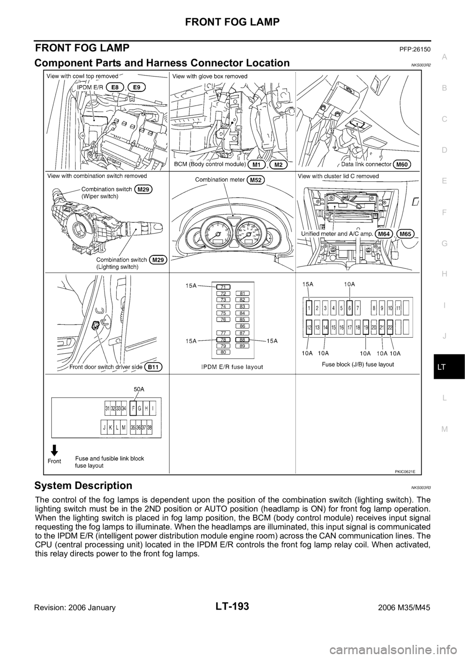
Component Parts and Harness Connector LocationNKS003R2
System DescriptionNKS003R3
The control of the fog lamps is dependent upon the position of the combination switch (lighting switch). The
lighting switch must be in the 2ND position or AUTO position (headlamp is ON) for front fog lamp operation.
When the lighting switch is placed in fog lamp position, the BCM (body control module) receives input signal
requesting the fog lamps to illuminate. When the headlamps are illuminated, this input signal is communicated
to the IPDM E/R (intelligent power distribution module engine room) across the CAN communication lines. The
CPU (central processing unit) located in the IPDM E/R controls the front fog lamp relay coil. When activated,
this relay directs power to the front fog lamps.
PKIC0621E
Page 4622 of 5621
FRONT FOG LAMP
LT-195
C
D
E
F
G
H
I
J
L
MA
B
LT
Revision: 2006 January2006 M35/M45
FOG LAMP OPERATION
The fog lamp switch is built in combination switch. The lighting switch must be in 2ND position or AUTO posi-
tion (headlamp is ON) and fog lamp switch must be ON for fog lamp operation.
With the fog lamp switch in the ON position, the CPU located in IPDM E/R grounds coil side of the fog lamp
relay. Fog lamp relay then directs power
through IPDM E/R terminal 37
to front fog lamp RH terminal 1,
through IPDM E/R terminal 36
to front fog lamp LH terminal 1.
Ground is supplied
to front fog lamp RH terminal 2
through grounds E22 and E43,
to front fog lamp LH terminal 2
through grounds E22 and E43.
With power and grounds supplied, the front fog lamps illuminate.
The unified meter and A/C amp. that received the front fog lamp request signal by BCM across the CAN com-
munication makes a front fog lamp indicator lamp turn on in combination meter.
COMBINATION SWITCH READING FUNCTION
Refer to BCS-3, "COMBINATION SWITCH READING FUNCTION" .
EXTERIOR LAMP BATTERY SAVER CONTROL
When the combination switch (lighting switch) is in the 2ND position (ON), and the ignition switch is turned
from ON or ACC to OFF, the battery saver control function is activated.
Under this condition, the headlamps remain illuminated for 5 minutes, then the headlamps are turned off.
Exterior lamp battery saver control mode can be changed by the function setting of CONSULT-II.
CAN Communication System DescriptionNKS003R4
CAN (Controller Area Network) is a serial communication line for real time application. It is an on-vehicle mul-
tiplex communication line with high data communication speed and excellent error detection ability. Many elec-
tronic control units are equipped onto a vehicle, and each control unit shares information and links with other
control units during operation (not independent). In CAN communication, control units are connected with 2
communication lines (CAN H line, CAN L line) allowing a high rate of information transmission with less wiring.
Each control unit transmits/receives data but selectively reads required data only.
CAN Communication UnitNKS003R5
Refer to LAN-34, "CAN Communication Unit" .
Page 4637 of 5621
LT-210
FRONT FOG LAMP
Revision: 2006 January2006 M35/M45
Bulb ReplacementNKS003RI
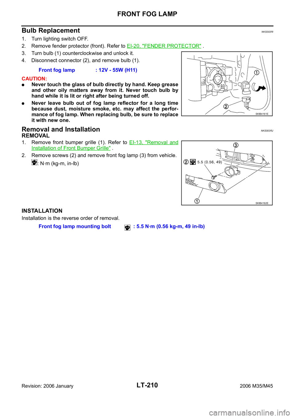
1. Turn lighting switch OFF.
2. Remove fender protector (front). Refer to EI-20, "
FENDER PROTECTOR" .
3. Turn bulb (1) counterclockwise and unlock it.
4. Disconnect connector (2), and remove bulb (1).
CAUTION:
Never touch the glass of bulb directly by hand. Keep grease
and other oily matters away from it. Never touch bulb by
hand while it is lit or right after being turned off.
Never leave bulb out of fog lamp reflector for a long time
because dust, moisture smoke, etc. may affect the perfor-
mance of fog lamp. When replacing bulb, be sure to replace
it with new one.
Removal and InstallationNKS003RJ
REMOVAL
1. Remove front bumper grille (1). Refer to EI-13, "Removal and
Installation of Front Bumper Grille" .
2. Remove screws (2) and remove front fog lamp (3) from vehicle.
: Nꞏm (kg-m, in-lb)
INSTALLATION
Installation is the reverse order of removal.Front fog lamp : 12V - 55W (H11)
SKIB4161E
SKIB4162E
Front fog lamp mounting bolt : 5.5 Nꞏm (0.56 kg-m, 49 in-lb)
Page 4676 of 5621
PARKING, LICENSE PLATE AND TAIL LAMPS
LT-249
C
D
E
F
G
H
I
J
L
MA
B
LT
Revision: 2006 January2006 M35/M45
PARKING, LICENSE PLATE AND TAIL LAMPSPFP:26550
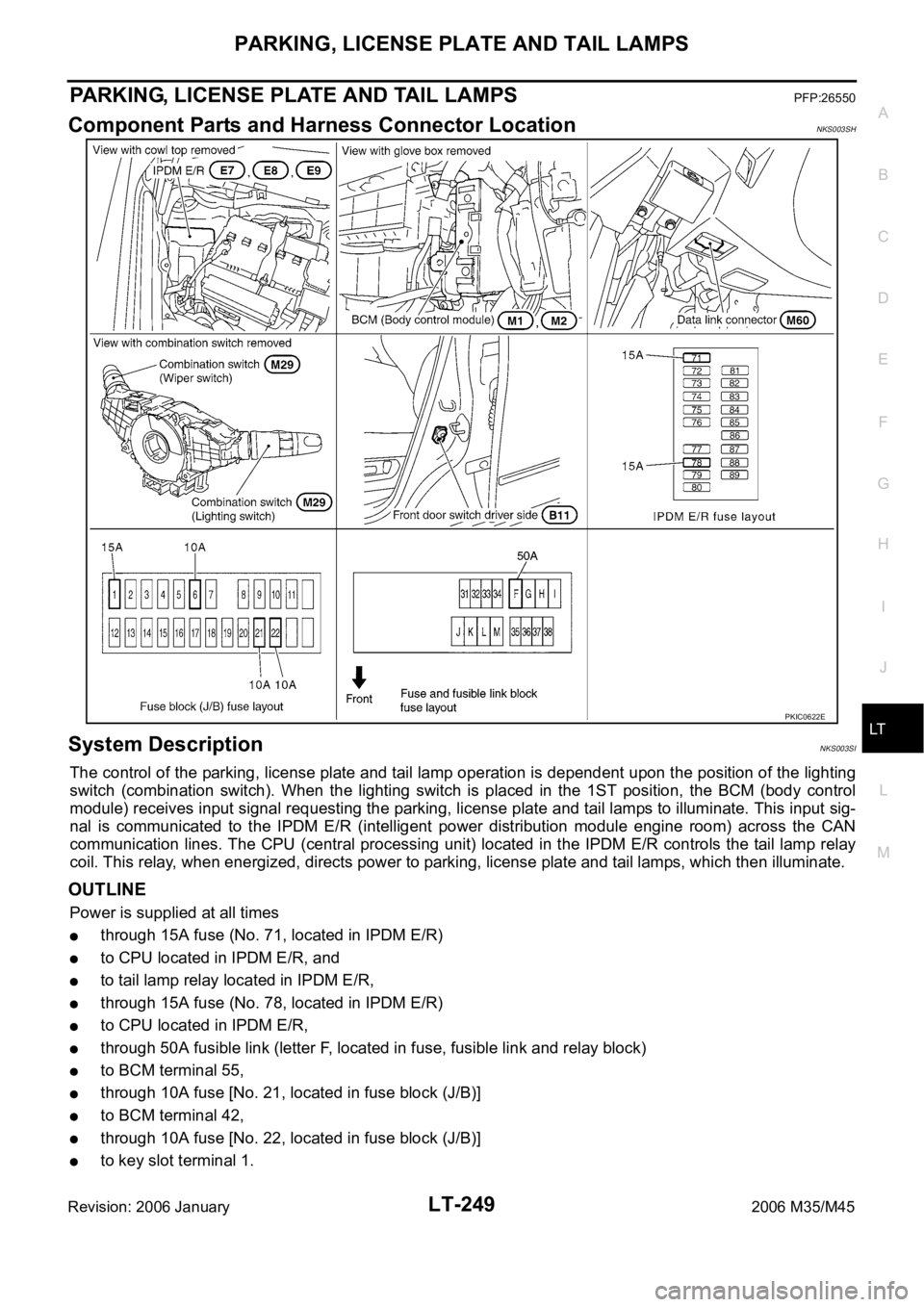
Component Parts and Harness Connector LocationNKS003SH
System DescriptionNKS003SI
The control of the parking, license plate and tail lamp operation is dependent upon the position of the lighting
switch (combination switch). When the lighting switch is placed in the 1ST position, the BCM (body control
module) receives input signal requesting the parking, license plate and tail lamps to illuminate. This input sig-
nal is communicated to the IPDM E/R (intelligent power distribution module engine room) across the CAN
communication lines. The CPU (central processing unit) located in the IPDM E/R controls the tail lamp relay
coil. This relay, when energized, directs power to parking, license plate and tail lamps, which then illuminate.
OUTLINE
Power is supplied at all times
through 15A fuse (No. 71, located in IPDM E/R)
to CPU located in IPDM E/R, and
to tail lamp relay located in IPDM E/R,
through 15A fuse (No. 78, located in IPDM E/R)
to CPU located in IPDM E/R,
through 50A fusible link (letter F, located in fuse, fusible link and relay block)
to BCM terminal 55,
through 10A fuse [No. 21, located in fuse block (J/B)]
to BCM terminal 42,
through 10A fuse [No. 22, located in fuse block (J/B)]
to key slot terminal 1.
PKIC0622E
Page 4677 of 5621
LT-250
PARKING, LICENSE PLATE AND TAIL LAMPS
Revision: 2006 January2006 M35/M45
With the ignition switch in the ON or START position, power is supplied
to CPU located in IPDM E/R,
through 15A fuse [No. 1, located in fuse block (J/B)]
to BCM terminal 38.
With the ignition switch in the ACC or ON position, power is supplied
through 10A fuse [No. 6, located in fuse block (J/B)]
to BCM terminal 11.
Ground is supplied
to BCM terminal 52
through grounds M16 and M70,
to IPDM E/R terminals 38 and 51
through grounds E22 and E43.
OPERATION BY LIGHTING SWITCH
With the lighting switch in the 1ST or 2ND position (or if the auto light system is activated), the BCM receives
input signal requesting the parking, license plate and tail lamps to illuminate. This input signal is communi-
cated to the IPDM E/R across the CAN communication lines. The CPU located in the IPDM E/R controls the
tail lamp relay coil, which when energized, directs power
through IPDM E/R terminal 21
to front combination lamp LH and RH terminals 5 (parking)
to front combination lamp LH and RH terminals 7 (side marker)
to rear combination lamp LH and RH terminals 1 (tail and side marker)
to license plate lamp LH and RH terminals 1.
Ground is supplied at all times
to front combination lamp LH and RH terminals 1 (parking and side marker)
through grounds E22 and E43,
to rear combination lamp LH and RH terminals 4 (tail and side marker)
to license plate lamp LH and RH terminals 2
through grounds B5, B40 and B131.
With power and ground supplied, the parking, license plate and tail lamps illuminate.
COMBINATION SWITCH READING FUNCTION
Refer toBCS-3, "COMBINATION SWITCH READING FUNCTION" .
EXTERIOR LAMP BATTERY SAVER CONTROL
When the combination switch (lighting switch) is in the 1ST (or 2ND) position, and ignition switch is turned
from ON or ACC to OFF, battery saver control feature is activated.
Under this condition, parking, license plate, side marker and tail lamps remain illuminated for 5 minutes, then
the parking, license plate, side marker and tail lamps are turned off.
Exterior lamp battery saver control mode can be changed by the function setting of CONSULT-II.
CAN Communication System DescriptionNKS003SJ
CAN (Controller Area Network) is a serial communication line for real time application. It is an on-vehicle mul-
tiplex communication line with high data communication speed and excellent error detection ability. Many elec-
tronic control units are equipped onto a vehicle, and each control unit shares information and links with other
control units during operation (not independent). In CAN communication, control units are connected with 2
communication lines (CAN H line, CAN L line) allowing a high rate of information transmission with less wiring.
Each control unit transmits/receives data but selectively reads required data only.
CAN Communication UnitNKS003SK
Refer to LAN-34, "CAN Communication Unit" .
Page 4722 of 5621
ILLUMINATION
LT-295
C
D
E
F
G
H
I
J
L
MA
B
LT
Revision: 2006 January2006 M35/M45
ILLUMINATIONPFP:27545
System DescriptionNKS003TH
Control of the illumination lamps operation is dependent upon the position of the lighting switch (combination
switch). When the lighting switch is placed in the 1ST or 2ND position (or if the auto light system is activated)
the BCM (body control module) receives input signal requesting the illumination lamps to illuminate. This input
signal is communicated to the IPDM E/R (intelligent power distribution module engine room) across the CAN
communication lines. The CPU (central processing unit) located in the IPDM E/R controls the tail lamp relay
coil. This relay, when energized, directs power to the illumination lamps, which then illuminate.
OUTLINE
Power is supplied at all times
through 15A fuse (No. 71, located in IPDM E/R)
to tail lamp relay, located in IPDM E/R, and
to CPU located in IPDM E/R,
through 15A fuse (No. 78, located in IPDM E/R)
to CPU located in IPDM E/R,
through 50A fusible link (letter F, located in fuse, fusible link and relay block)
to BCM terminal 55,
through 10A fuse [No. 21, located in fuse block (J/B)]
to BCM terminal 42 and
to combination meter terminal 23,
through 10A fuse [No. 19, located in fuse block (J/B)]
to unified meter and A/C amp. terminal 54,
through 10A fuse [No. 22, located in fuse block (J/B)]
to intelligent key unit terminals 1, 41 and 57.
With the ignition switch in the ON or START position, power is supplied
through 15A fuse [No. 1, located in fuse block (J/B)]
to BCM terminal 38,
through 10A fuse [No. 14, located in fuse block (J/B)]
to combination meter terminal 12,
through 10A fuse [No. 12, located in fuse block (J/B)]
to unified meter and A/C amp. terminal 53 and
to rear sunshade cancel relay terminal 1.
With the ignition switch in the ACC or ON position, power is supplied
through 10A fuse [No. 6, located in fuse block (J/B)]
to BCM terminal 11
to unified meter and A/C amp. terminal 41 and
to combination meter terminal 2.
Ground is supplied
to BCM terminal 52
to unified meter and A/C amp. terminals 55 and 71
to combination meter terminals 9, 10, and 11
to Intelligent Key unit terminals 20, 40, 56 and 72, and
to illumination control switch terminal 3
through grounds M16 and M70,
to IPDM E/R terminals 38 and 51
through grounds E22 and E43.
Page 4723 of 5621

LT-296
ILLUMINATION
Revision: 2006 January2006 M35/M45
ILLUMINATION OPERATION BY LIGHTING SWITCH
With the lighting switch in the 1ST or 2ND position (or if the auto light system is activated), the BCM receives
input signal requesting the illumination lamps to illuminate. This input signal is communicated to the IPDM E/R
across the CAN communication lines. The CPU located in the IPDM E/R controls the tail lamp relay coil,
which, when energized, directs power
through IPDM E/R terminal 21
to combination meter terminal 13
to LDW switch (illumination) terminal 5 (with lane departure warning)
to VDC off switch (illumination) terminal 3
to trunk lid opener switch (illumination) terminal 3
to combination switch (spiral cable) terminal 24
to door mirror remote control switch (illumination) terminal 16
to AFS switch (illumination) terminal 5 (with AFS)
to rear sunshade front switch (illumination) terminal 5 (with rear control switch)
to A/T illumination terminal 1
to snow mode switch (illumination) terminal 5 (AWD models)
to rear control cancel switch (illumination) terminal 4 (with rear control switch)
to clock terminal 3
to multifunction switch terminal 3
to audio unit terminal 9
to DVD player terminal 18 (with DVD player)
to NAVI control unit terminal 61 (with navigation system)
to AV control unit terminal 61 (without navigation system)
to climate controlled seat switch driver side (illumination) terminal 7 (with climate controlled seat)
to climate controlled seat switch passenger side (illumination) terminal 7 (with climate controlled seat)
to ashtray illumination (rear LH) terminal 1
to ashtray illumination (rear RH) terminal 1
to illumination control switch terminal 1
to cigarette lighter socket (illumination) terminal 2
to map lamp (illumination) terminal 8
to power window main switch illumination terminal 1
to glove box lamp terminal 1
to rear control switch terminal 2
to rear power seat switch RH (illumination) terminal 4 (with rear control switch)
to rear heated seat switch RH (illumination) terminal 7 (with rear control switch)
to rear sunshade cancel relay terminal 6 (with rear control switch)
to automatic return cancel switch (illumination) terminal 4 (with rear control switch)
to rear power seat switch LH (illumination) terminal 4 (with rear control switch) and
to rear heated seat switch LH (illumination) terminal 7 (with rear control switch),
through Intelligent Key unit terminal 12
to push button ignition switch (illumination) terminal 3.
Ground is supplied
to combination meter terminal 14
to combination meter terminal 9, 10 and 11
to push button ignition switch (illumination) terminal 2
to LDW switch (illumination) terminal 4 (with lane departure warning)
to VDC off switch (illumination) terminal 4
to trunk lid opener switch (illumination) terminal 4
to combination switch (spiral cable) terminal 25
Page 4744 of 5621
LU-1
ENGINE LUBRICATION SYSTEM
B ENGINE
CONTENTS
C
D
E
F
G
H
I
J
K
L
M
SECTION LU
A
LU
Revision: 2006 January2006 M35/M45
ENGINE LUBRICATION SYSTEM
VQ35DE
PRECAUTIONS .......................................................... 3
Precautions for Liquid Gasket .................................. 3
LIQUID GASKET APPLICATION PROCEDURE ..... 3
PREPARATION ........................................................... 4
Special Service Tools ............................................... 4
Commercial Service Tools ........................................ 4
LUBRICATION SYSTEM ............................................ 5
Lubrication Circuit .................................................... 5
System Chart ........................................................... 6
ENGINE OIL ............................................................... 7
Inspection ................................................................. 7
ENGINE OIL LEVEL ............................................. 7
ENGINE OIL APPEARANCE ................................ 7
ENGINE OIL LEAKAGE ........................................ 7
OIL PRESSURE CHECK ...................................... 8
Changing Engine Oil ................................................ 9
OIL FILTER ............................................................... 10
Removal and Installation ........................................ 10
REMOVAL ........................................................
... 10
INSTALLATION ................................................... 10
INSPECTION AFTER INSTALLATION ............... 10
OIL FILTER BRACKET (AWD) ................................. 12
Components ........................................................... 12
Removal and Installation ........................................ 12
REMOVAL ........................................................
... 12
INSTALLATION ................................................... 12
INSPECTION AFTER INSTALLATION ............... 13
OIL COOLER ............................................................ 14
Components ........................................................... 14
Removal and Installation ........................................ 15
REMOVAL ........................................................
... 15
INSPECTION AFTER REMOVAL ....................... 16
INSTALLATION ................................................... 16
INSPECTION AFTER INSTALLATION ............... 16
OIL PUMP ................................................................. 18
Components ........................................................... 18
Removal and Installation ........................................ 18
REMOVAL ........................................................
... 18
INSTALLATION ................................................... 18INSPECTION AFTER INSTALLATION ................ 18
Disassembly and Assembly .................................... 18
DISASSEMBLY ................................................... 18
INSPECTION AFTER DISASSEMBLY ................ 19
ASSEMBLY ......................................................... 20
SERVICE DATA AND SPECIFICATIONS (SDS) ...... 21
Standard and Limit .................................................. 21
ENGINE OIL PRESSURE ................................... 21
ENGINE OIL CAPACITY (APPROXIMATE) ........ 21
OIL PUMP ........................................................... 21
REGULATOR VALVE .......................................... 21
VK45DE
PRECAUTIONS ........................................................ 22
Precautions for Liquid Gasket ................................ 22
LIQUID GASKET APPLICATION PROCEDURE ... 22
PREPARATION ......................................................... 23
Special Service Tools ............................................. 23
Commercial Service Tools ...................................... 23
LUBRICATION SYSTEM .......................................... 24
Lubrication Circuit ................................................... 24
System Chart .......................................................... 25
ENGINE OIL .............................................................. 26
Inspection ............................................................... 26
ENGINE OIL LEVEL ............................................ 26
ENGINE OIL APPEARANCE .............................. 26
ENGINE OIL LEAKAGE ...................................... 26
OIL PRESSURE CHECK .................................... 26
Changing Engine Oil ............................................
... 28
OIL FILTER ............................................................... 29
Removal and Installation ........................................ 29
REMOVAL ........................................................
... 29
INSTALLATION ................................................... 29
INSPECTION AFTER INSTALLATION ................ 29
OIL PUMP ................................................................. 30
Components ........................................................... 30
Removal and Installation ........................................ 30
REMOVAL ........................................................
... 30
INSTALLATION ................................................... 30
Page 4745 of 5621

LU-2Revision: 2006 January2006 M35/M45 INSPECTION AFTER INSTALLATION ................ 31
Disassembly and Assembly .................................... 31
DISASSEMBLY ................................................... 31
INSPECTION AFTER DISASSEMBLY ................ 31
ASSEMBLY ......................................................... 32SERVICE DATA AND SPECIFICATIONS (SDS) ...... 33
Standard and Limit .................................................. 33
ENGINE OIL PRESSURE .................................... 33
ENGINE OIL CAPACITY (APPROXIMATE) ........ 33
OIL PUMP ............................................................ 33
REGULATOR VALVE ........................................... 33
Page 4746 of 5621
![INFINITI M35 2006 Factory Service Manual PRECAUTIONS
LU-3
[VQ35DE]
C
D
E
F
G
H
I
J
K
L
MA
LU
Revision: 2006 January2006 M35/M45
[VQ35DE]PRECAUTIONSPFP:00001
Precautions for Liquid GasketNBS004PR
LIQUID GASKET APPLICATION PROCEDURE
1. Remove INFINITI M35 2006 Factory Service Manual PRECAUTIONS
LU-3
[VQ35DE]
C
D
E
F
G
H
I
J
K
L
MA
LU
Revision: 2006 January2006 M35/M45
[VQ35DE]PRECAUTIONSPFP:00001
Precautions for Liquid GasketNBS004PR
LIQUID GASKET APPLICATION PROCEDURE
1. Remove](/img/42/57023/w960_57023-4745.png)
PRECAUTIONS
LU-3
[VQ35DE]
C
D
E
F
G
H
I
J
K
L
MA
LU
Revision: 2006 January2006 M35/M45
[VQ35DE]PRECAUTIONSPFP:00001
Precautions for Liquid GasketNBS004PR
LIQUID GASKET APPLICATION PROCEDURE
1. Remove old liquid gasket adhering to the liquid gasket application surface and the mating surface.
Remove liquid gasket completely from the liquid gasket application surface, mounting bolts, and bolt
holes.
2. Wipe the liquid gasket application surface and the mating surface with white gasoline (lighting and heating
use) to remove adhering moisture, grease and foreign materials.
3. Apply liquid gasket to the liquid gasket application surface.
Use Genuine RTV Silicone Sealant or equivalent. Refer to GI-48, "
RECOMMENDED CHEMICAL
PRODUCTS AND SEALANTS" .
Within five minutes of liquid gasket application, install the mating component.
If liquid gasket protrudes, wipe it off immediately.
Do not retighten mounting bolts or nuts after the installation.
After 30 minutes or more have passed from the installation, fill engine oil and engine coolant.