INFINITI M35 2006 Factory Service Manual
Manufacturer: INFINITI, Model Year: 2006, Model line: M35, Model: INFINITI M35 2006Pages: 5621, PDF Size: 65.56 MB
Page 4861 of 5621

PG-34
PDU (POWER DISTRIBUTION UNIT)
Revision: 2006 January2006 M35/M45
*1: When the A/T selector lever position is N position, the engine start condition is different according to the vehicle speed.
At vehicle speed of 5 km/h or less, the engine can start only when the brake pedal is depressed.
At vehicle speed of 5 km/h or more, the engine can start even if the brake pedal is not depressed. (It is the same as “Engine stall
return operation while driving”.)
*2: When the A/T selector lever position is any position other than P position and when the vehicle speed is 5 km/h or more, the engine
stop condition is different.
Press and hold the push-button ignition switch for 2 seconds or more. (When the push-button ignition switch is pressed for too short
a time, the operation may be invalid, so properly press and hold to prevent the incorrect operation.)
Press the push-button ignition switch 3 times within 1.5 seconds. (Emergency stop operation) Power supply positionEngine start/stop condition Push-button ignition
switch operation fre-
quency Brake pedal operation condition A/T selector lever position
LOCK
ACCNot depressed
(When A/T selector lever is in any posi-
tion other than P or N, there will be no
effect even if it is depressed.)Any position other than P or N
(When the brake pedal is not
depressed, there will be no effect even
if the A/T selector lever is in P or N
position.)1
LOCK
ACC ONNot depressed
(When A/T selector lever is in any posi-
tion other than P or N, there will be no
effect even if it is depressed.)Any position other than P or N
(When the brake pedal is not
depressed, there will be no effect even
if the A/T selector lever is in P or N
position.)2
LOCK
ACC ON
LOCKNot depressed
(When A/T selector lever is in any posi-
tion other than P or N, there will be no
effect even if it is depressed.)Any position other than P or N
(When the brake pedal is not
depressed, there will be no effect even
if the A/T selector lever is in P or N
position.)3
LOCK
START
ACC
START
ON
START
(Engine start)Depressed P or N position (*1)1
[If the switch is
pushed once, the
engine starts from
any power supply
position (LOCK,
ACC, and ON)]
Engine start condition
LOCK
(Engine stop)— P position 1
Engine start condition
ACC
(Engine stop)— Any position other than P (*2) 1
Engine stall return
operation while driving— N position 1
Page 4862 of 5621

PDU (POWER DISTRIBUTION UNIT)
PG-35
C
D
E
F
G
H
I
J
L
MA
B
PG
Revision: 2006 January2006 M35/M45
Wiring Diagram — PDU —NKS004EF
TKWT3320E
Page 4863 of 5621
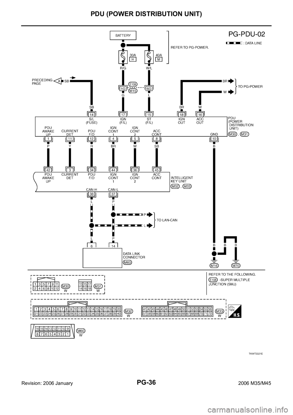
PG-36
PDU (POWER DISTRIBUTION UNIT)
Revision: 2006 January2006 M35/M45
TKWT3321E
Page 4864 of 5621

PDU (POWER DISTRIBUTION UNIT)
PG-37
C
D
E
F
G
H
I
J
L
MA
B
PG
Revision: 2006 January2006 M35/M45
Terminals and Reference Value for Intelligent Key UnitNKS004EG
Te r m i -
nalWire
ColorItemCondition
Voltage (V)
Approx. Ignition
Switch
PositionOperation or Conditions
1 SB Power source (Fuse) LOCK — Battery voltage
3 Y IPDM E/R status signal —Engine starting (During Cranking) 5
Other than above 2
8WPush-button ignition
switch
(LOCK LED)LOCK Push-button ignition switch is in LOCK position 0
—Push-button ignition switch is in any position
(Except LOCK position)1.2
9LPush-button ignition
switch
(ACC LED)ACC Push-button ignition switch is in ACC position 0
—Push-button ignition switch is in any position
(Except ACC position)1.2
10 VPush-button ignition
switch
(ON LED)ON Push-button ignition switch is in ON position 0
—Push-button ignition switch is in any position
(Except ON position)1.2
20 B Ground — — 0
30 L/W Ignition switch (ACC) ACC — Battery voltage
31 GR Ignition switch (ON) ON — Battery voltage
34 R PDU feedback signal LOCKPush-button ignition switch is in LOCK state, 30 sec-
onds after all doors closed1
Other than above 0
36 W Ignition signal 2LOCK — Battery voltage
ACC — Battery voltage
ON — 0
37 P CAN-L — — —
38 L CAN-H — — —
39 BR/W Push switch —Depress push-button ignition switch 0
Unpress push-button ignition switch Battery voltage
40 B Ground — — 0
41 Y Power source (Fuse) LOCK — Battery voltage
42 P PDU wake up signal LOCKPush-button ignition switch is in LOCk state, 30 sec-
onds after all doors closedBattery voltage
Other than above 0
44 BR Ignition signal 1LOCK — Battery voltage
ACC — Battery voltage
ON — 0
45 SB ACC signalLOCK — Battery voltage
ACC — 0
ON — 0
56 B Ground — — 0
57 L Power source (Fuse) LOCK — Battery voltage
72 B Ground — — 0
Page 4865 of 5621

PG-38
PDU (POWER DISTRIBUTION UNIT)
Revision: 2006 January2006 M35/M45
Terminals and Reference Value for PDUNKS004EH
Work FlowNKS004EI
1. Check the symptom and customer's requests.
2. Understand outline of system. Refer to PG-33, "
System Description" .
3. Confirm that Intelligent Key system operates normally.
Refer to BL-24, "
POWER DOOR LOCK SYSTEM" .
4. Repair or replace any malfunctioning parts.
Refer to PG-39, "
Trouble Diagnosis Symptom Chart" .
5. INSPECTION END
Te r m i -
nalWire
ColorItemCondition
Voltage (V)
Approx. Ignition
Switch
PositionOperation or Conditions
1 P PDU wake up signal LOCKPush-button ignition switch is in LOCK state, 30 sec-
onds after all doors closeBattery voltage
Other than above 0
4 BR Ignition signal 1LOCK — Battery voltage
ACC — Battery voltage
ON — 0
5 W Ignition signal 2LOCK — Battery voltage
ACC — Battery voltage
ON — 0
8 SB ACC signalLOCK — Battery voltage
ACC — 0
ON — 0
10 B Ground — — 0
11 Y IPDM E/R status signal —Engine starting (During Cranking) 5
Other than above 2
12 R PDU feedback signal LOCKPush-button ignition switch is in LOCK state, 30 sec-
onds after all doors close1
Other than above 0
14 SB Power source (Fuse) LOCK — Battery voltage
15 L Power source (F/L) LOCK — Battery voltage
16 W ACC power outputLOCK — 0
ACC — Battery voltage
ON — Battery voltage
17 G Power source (Fuse) LOCK — Battery voltage
18 BR ON power outputLOCK — 0
ACC — 0
ON — Battery voltage
Page 4866 of 5621
PDU (POWER DISTRIBUTION UNIT)
PG-39
C
D
E
F
G
H
I
J
L
MA
B
PG
Revision: 2006 January2006 M35/M45
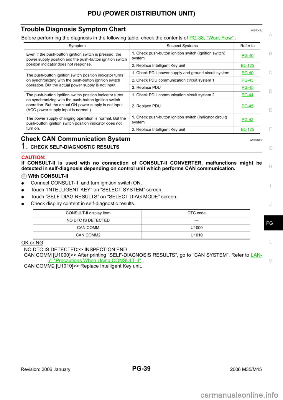
Trouble Diagnosis Symptom ChartNKS004EJ
Before performing the diagnosis in the following table, check the contents of PG-38, "Work Flow" .
Check CAN Communication SystemNKS004EK
1. CHECK SELF-DIAGNOSTIC RESULTS
CAUTION:
If CONSULT-II is used with no connection of CONSULT-II CONVERTER, malfunctions might be
detected in self-diagnosis depending on control unit which performs CAN communication.
With CONSULT-II
Connect CONSULT-II, and turn ignition switch ON.
Touch “INTELLIGENT KEY” on “SELECT SYSTEM” screen.
Touch “SELF-DIAG RESULTS” on “SELECT DIAG MODE” screen.
Check display content in self-diagnostic results.
OK or NG
NO DTC IS DETECTED>> INSPECTION END
CAN COMM [U1000]>> After printing “SELF-DIAGNOSIS RESULTS”, go to “CAN SYSTEM”, Refer to LAN-
7, "Precautions When Using CONSULT-II" .
CAN COMM2 [U1010]>> Replace Intelligent Key unit.
Symptom Suspect Systems Refer to
Even if the push-button ignition switch is pressed, the
power supply position and the push-button ignition switch
position indicator does not response.1. Check push-button ignition switch (ignition switch)
systemPG-40
2. Replace Intelligent Key unitBL-125
The push-button ignition switch position indicator turns
on synchronizing with the push-button ignition switch
operation. But the actual power supply is not input.1. Check PDU power supply and ground circuit systemPG-40
2. Check PDU communication circuit system 1PG-43
3. Replace PDUPG-45
The push-button ignition switch position indicator turns
on synchronizing with the push-button ignition switch
operation. But the actual ON power supply is not input.
(ACC power supply input is normal.)1. Check PDU communication circuit system 2PG-44
2. Replace PDUPG-45
The power supply changing operation is normal. But the
push-button ignition switch position indicator does not
turn on.1. Check push-button ignition switch (indicator circuit)
systemPG-42
2. Replace Intelligent Key unitBL-125
CONSULT-II display item DTC code
NO DTC IS DETECTED —
CAN COMM U1000
CAN COMM2 U1010
Page 4867 of 5621
PG-40
PDU (POWER DISTRIBUTION UNIT)
Revision: 2006 January2006 M35/M45
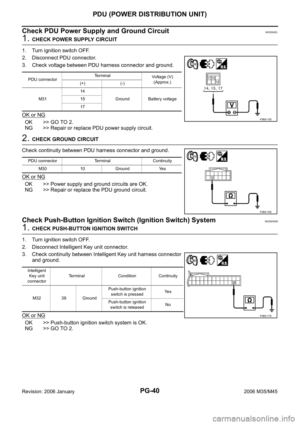
Check PDU Power Supply and Ground CircuitNKS004EL
1. CHECK POWER SUPPLY CIRCUIT
1. Turn ignition switch OFF.
2. Disconnect PDU connector.
3. Check voltage between PDU harness connector and ground.
OK or NG
OK >> GO TO 2.
NG >> Repair or replace PDU power supply circuit.
2. CHECK GROUND CIRCUIT
Check continuity between PDU harness connector and ground.
OK or NG
OK >> Power supply and ground circuits are OK.
NG >> Repair or replace the PDU ground circuit.
Check Push-Button Ignition Switch (Ignition Switch) SystemNKS004EM
1. CHECK PUSH-BUTTON IGNITION SWITCH
1. Turn ignition switch OFF.
2. Disconnect Intelligent Key unit connector.
3. Check continuity between Intelligent Key unit harness connector
and ground.
OK or NG
OK >> Push-button ignition switch system is OK.
NG >> GO TO 2.
PDU connectorTerminal
Voltage (V)
(Approx.)
(+) (-)
M3114
Ground Battery voltage 15
17
PIIB6115E
PDU connector Terminal Continuity
M30 10 Ground Yes
PIIB6116E
Intelligent
Key unit
connectorTerminal Condition Continuity
M32 39 GroundPush-button ignition
switch is pressedYe s
Push-button ignition
switch is releasedNo
PIIB6117E
Page 4868 of 5621
PDU (POWER DISTRIBUTION UNIT)
PG-41
C
D
E
F
G
H
I
J
L
MA
B
PG
Revision: 2006 January2006 M35/M45
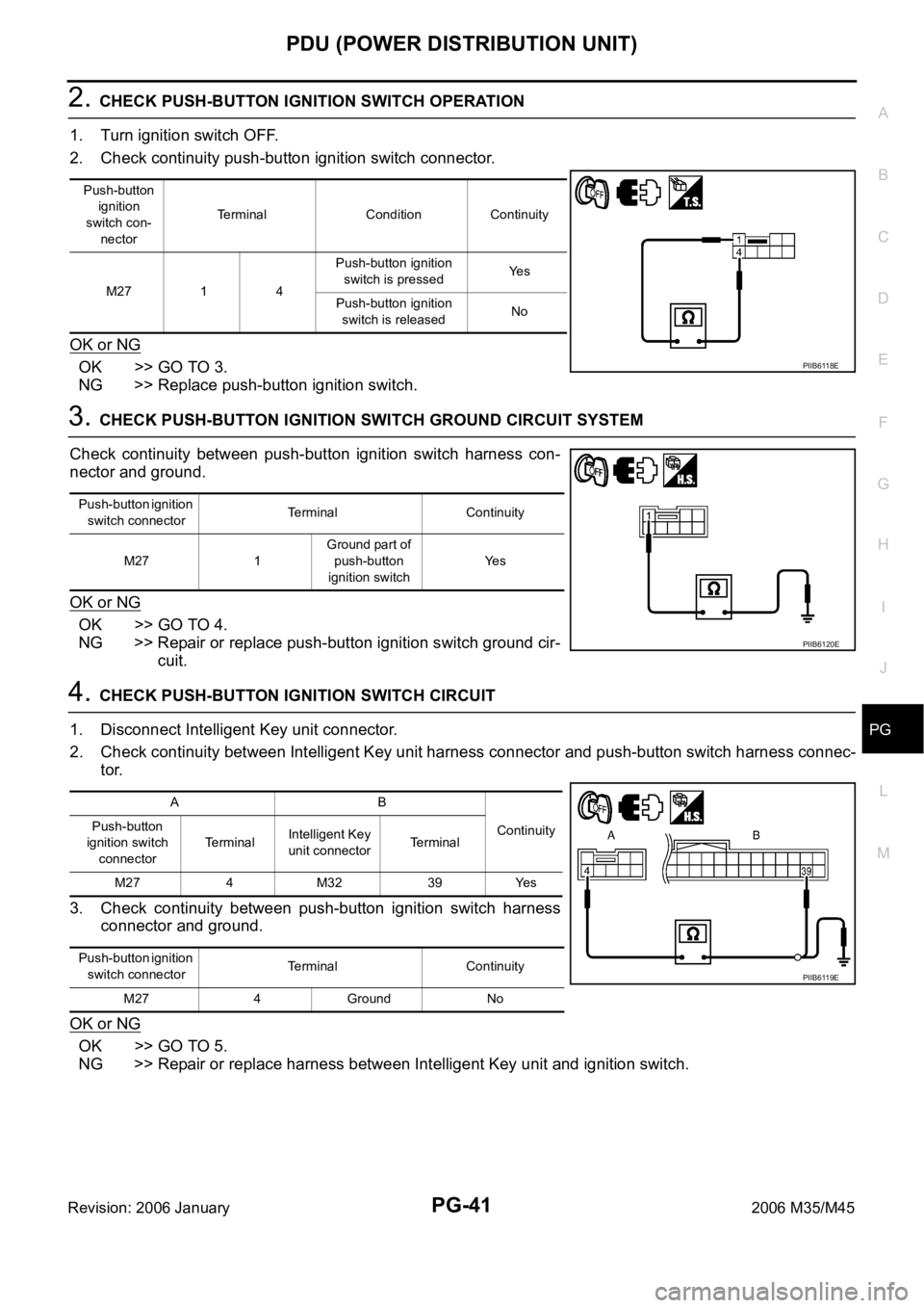
2. CHECK PUSH-BUTTON IGNITION SWITCH OPERATION
1. Turn ignition switch OFF.
2. Check continuity push-button ignition switch connector.
OK or NG
OK >> GO TO 3.
NG >> Replace push-button ignition switch.
3. CHECK PUSH-BUTTON IGNITION SWITCH GROUND CIRCUIT SYSTEM
Check continuity between push-button ignition switch harness con-
nector and ground.
OK or NG
OK >> GO TO 4.
NG >> Repair or replace push-button ignition switch ground cir-
cuit.
4. CHECK PUSH-BUTTON IGNITION SWITCH CIRCUIT
1. Disconnect Intelligent Key unit connector.
2. Check continuity between Intelligent Key unit harness connector and push-button switch harness connec-
tor.
3. Check continuity between push-button ignition switch harness
connector and ground.
OK or NG
OK >> GO TO 5.
NG >> Repair or replace harness between Intelligent Key unit and ignition switch.
Push-button
ignition
switch con-
nectorTerminal Condition Continuity
M27 1 4Push-button ignition
switch is pressedYe s
Push-button ignition
switch is releasedNo
PIIB6118E
Push-button ignition
switch connectorTerminal Continuity
M27 1Ground part of
push-button
ignition switchYe s
PIIB6120E
AB
Continuity Push-button
ignition switch
connectorTerminalIntelligent Key
unit connectorTerminal
M27 4 M32 39 Yes
Push-button ignition
switch connectorTerminal Continuity
M27 4 Ground No
PIIB6119E
Page 4869 of 5621
PG-42
PDU (POWER DISTRIBUTION UNIT)
Revision: 2006 January2006 M35/M45
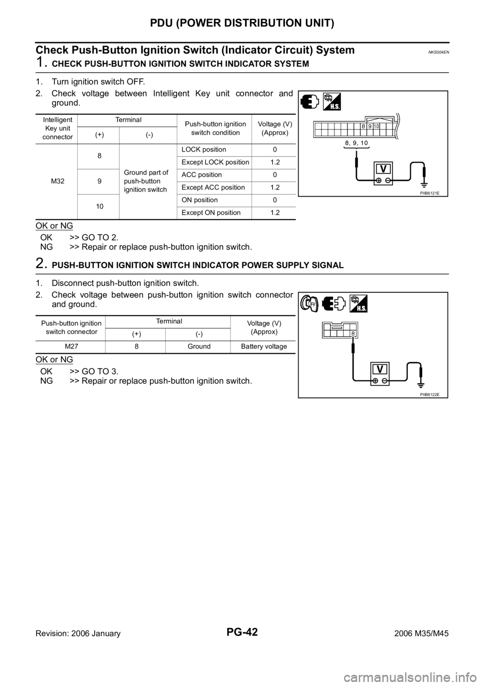
Check Push-Button Ignition Switch (Indicator Circuit) SystemNKS004EN
1. CHECK PUSH-BUTTON IGNITION SWITCH INDICATOR SYSTEM
1. Turn ignition switch OFF.
2. Check voltage between Intelligent Key unit connector and
ground.
OK or NG
OK >> GO TO 2.
NG >> Repair or replace push-button ignition switch.
2. PUSH-BUTTON IGNITION SWITCH INDICATOR POWER SUPPLY SIGNAL
1. Disconnect push-button ignition switch.
2. Check voltage between push-button ignition switch connector
and ground.
OK or NG
OK >> GO TO 3.
NG >> Repair or replace push-button ignition switch.
Intelligent
Key unit
connectorTe r m i n a l
Push-button ignition
switch conditionVoltage (V)
(Approx)
(+) (-)
M328
Ground part of
push-button
ignition switchLOCK position 0
Except LOCK position 1.2
9ACC position 0
Except ACC position 1.2
10ON position 0
Except ON position 1.2
PIIB6121E
Push-button ignition
switch connectorTerminal
Voltage (V)
(Approx)
(+) (-)
M27 8 Ground Battery voltage
PIIB6122E
Page 4870 of 5621
PDU (POWER DISTRIBUTION UNIT)
PG-43
C
D
E
F
G
H
I
J
L
MA
B
PG
Revision: 2006 January2006 M35/M45
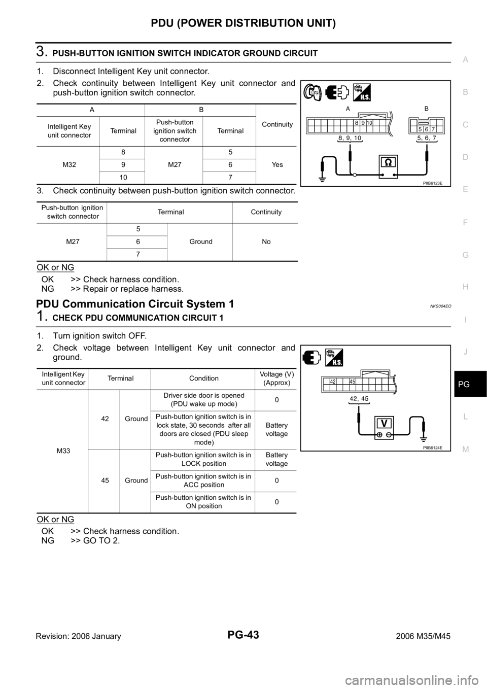
3. PUSH-BUTTON IGNITION SWITCH INDICATOR GROUND CIRCUIT
1. Disconnect Intelligent Key unit connector.
2. Check continuity between Intelligent Key unit connector and
push-button ignition switch connector.
3. Check continuity between push-button ignition switch connector.
OK or NG
OK >> Check harness condition.
NG >> Repair or replace harness.
PDU Communication Circuit System 1NKS004EO
1. CHECK PDU COMMUNICATION CIRCUIT 1
1. Turn ignition switch OFF.
2. Check voltage between Intelligent Key unit connector and
ground.
OK or NG
OK >> Check harness condition.
NG >> GO TO 2.
AB
Continuity
Intelligent Key
unit connectorTerminalPush-button
ignition switch
connectorTe r m i n a l
M328
M275
Ye s 96
10 7
P u s h - b u t t o n i g n i t i o n
switch connectorTerminal Continuity
M275
Ground No 6
7
PIIB6123E
Intelligent Key
unit connectorTerminal ConditionVoltage (V)
(Approx)
M3342 GroundDriver side door is opened
(PDU wake up mode)0
Push-button ignition switch is in
lock state, 30 seconds after all
doors are closed (PDU sleep
mode)Battery
voltage
45 GroundPush-button ignition switch is in
LOCK positionBattery
voltage
Push-button ignition switch is in
ACC position0
Push-button ignition switch is in
ON position0
PIIB6124E