turn signal INFINITI M35 2006 Factory Service Manual
[x] Cancel search | Manufacturer: INFINITI, Model Year: 2006, Model line: M35, Model: INFINITI M35 2006Pages: 5621, PDF Size: 65.56 MB
Page 5496 of 5621

TROUBLE DIAGNOSIS FOR SYSTEM
TF-31
C
E
F
G
H
I
J
K
L
MA
B
TF
Revision: 2006 January2006 M35/M45
3. Check resistance between transfer assembly harness connector
F43 terminals 1 and 2.
4. If NG, replace electric controlled coupling. Refer to TF-45, "
Dis-
assembly and Assembly" .
AWD Ac tua t or R el a yNDS000DR
CONSULT-II REFERENCE VALUE IN DATA MONITOR MODE
Data are reference value.
DIAGNOSTIC PROCEDURE
Check the following if “4WD ACTUATOR RLY [C1205]” is displayed in self-diagnosis results of CONSULT-
II.
1. CHECK AWD SOLENOID SYSTEM
Perform self-diagnosis. Refer to TF-22, "
SELF-DIAG RESULT MODE" .
Is the
“4WD SOLENOID [C1204]” displayed?
YES >> Perform trouble diagnosis for AWD solenoid. Refer to TF-28, "AWD Solenoid" .
NO >> GO TO 2.
2. CHECK AWD ACTUATOR RELAY SIGNAL
With CONSULT-II
1. Turn ignition switch “ON”. (Do not start engine.)
2. Select “DATA MONITOR” mode for “ALL MODE AWD/4WD” with CONSULT- I I .
3. Start engine and read out ON/OFF signal of “ETS ACTUATOR”.
OK or NG
OK >> GO TO 4.
NG >> GO TO 3.
3. CHECK AWD CONTROL UNIT
Check AWD control unit input/output signal. Refer to TF-20, "
AWD Control Unit Input/Output Signal Reference
Va l u e s" .
OK or NG
OK >> GO TO 4.
NG >> Check AWD control unit pin terminals for damage or loose connection with harness connector. If
any items are damaged, repair or replace damaged parts. 1 - 2 : Approx. 2.45
SDIA2162E
Monitor item Condition Display value
ETS ACTUATOR [ON/OFF]Engine stopped (Ignition switch: ON) OFF
Engine running ON
Monitor item Condition Display value
ETS ACTUATOREngine stopped (Ignition switch: ON) OFF
Engine running ON
SDIA1897E
Page 5497 of 5621

TF-32
TROUBLE DIAGNOSIS FOR SYSTEM
Revision: 2006 January2006 M35/M45
4. CHECK DTC
Perform the self-diagnosis, after driving a vehicle for a while.
OK or NG
OK >>INSPECTION END
NG >> Replace AWD control unit.
Engine Control SignalNDS000DS
DIAGNOSTIC PROCEDURE
Check the following if “ECM SIGNAL 1 [C1210]” is displayed in self-diagnosis results of CONSULT-II.
1. CHECK DTC WITH ECM
Perform self-diagnosis with ECM. Refer to EC-55, "
Emission-Related Diagnostic Information" .
Is any malfunction detected by self-diagnosis?
YES >> Check the malfunctioning system.
NO >> GO TO 2.
2. CHECK AWD CONTROL UNIT
Check AWD control unit input/output signal. Refer to TF-20, "
AWD Control Unit Input/Output Signal Reference
Va l u e s" .
OK or NG
OK >> GO TO 3.
NG >> Check AWD control unit pin terminals for damage or loose connection with harness connector. If
any items are damaged, repair or replace damaged parts.
3. CHECK DTC
Perform the self-diagnosis, after driving a vehicle for a while.
OK or NG
OK >>INSPECTION END
NG >> Perform self-diagnosis with ECM again. Refer to EC-55, "
Emission-Related Diagnostic Informa-
tion" .
CAN Communication LineNDS000DT
DIAGNOSTIC PROCEDURE
Check the following if “CAN COMM CIRCUIT [U1000]” is detected in self-diagnosis results of CONSULT-
II.
1. CHECK CAN COMMUNICATION CIRCUIT
With CONSULT-II
1. Turn ignition switch “ON” and start engine.
2. Select “SELF-DIAG RESULTS” mode for “ALL MODE AWD/4WD” with in CONSULT-II.
3. Perform the self-diagnosis.
Is the
“CAN COMM CIRCUIT [U1000]” displayed?
YES >> Print out CONSULT-II screen and go to LAN-7, "Precau-
tions When Using CONSULT-II" .
NO >>INSPECTION END
SDIA1850E
Page 5498 of 5621

TROUBLE DIAGNOSIS FOR SYMPTOMS
TF-33
C
E
F
G
H
I
J
K
L
MA
B
TF
Revision: 2006 January2006 M35/M45
TROUBLE DIAGNOSIS FOR SYMPTOMSPFP:00007
AWD Warning Lamp Does Not Turn ON When The Ignition Switch Is Turned to
ON
NDS000DU
DIAGNOSTIC PROCEDURE
1. CHECK SYSTEM FOR CAN COMMUNICATION LINE
Perform self-diagnosis. Refer to TF-22, "
SELF-DIAG RESULT MODE" .
Is the
“CAN COMM CIRCUIT [U1000]” displayed?
YES >> Perform trouble diagnosis for CAN communication line. Refer to TF-32, "CAN Communication
Line" .
NO >> GO TO 2.
2. CHECK AWD CONTROL UNIT
Check AWD control unit input/output signal. Refer to TF-20, "
AWD Control Unit Input/Output Signal Reference
Va l u e s" .
OK or NG
OK >> GO TO 3.
NG >> Check AWD control unit pin terminals for damage or loose connection with harness connector. If
any items are damaged, repair or replace damaged parts.
3. CHECK OUTPUT SIGNAL WITH UNIFIED METER AND A/C AMP.
With CONSULT-II
1. Turn ignition switch “ON”. (Do not start engine.)
2. Select “DATA MONITOR” mode for “METER A/C AMP” with CONSULT-II.
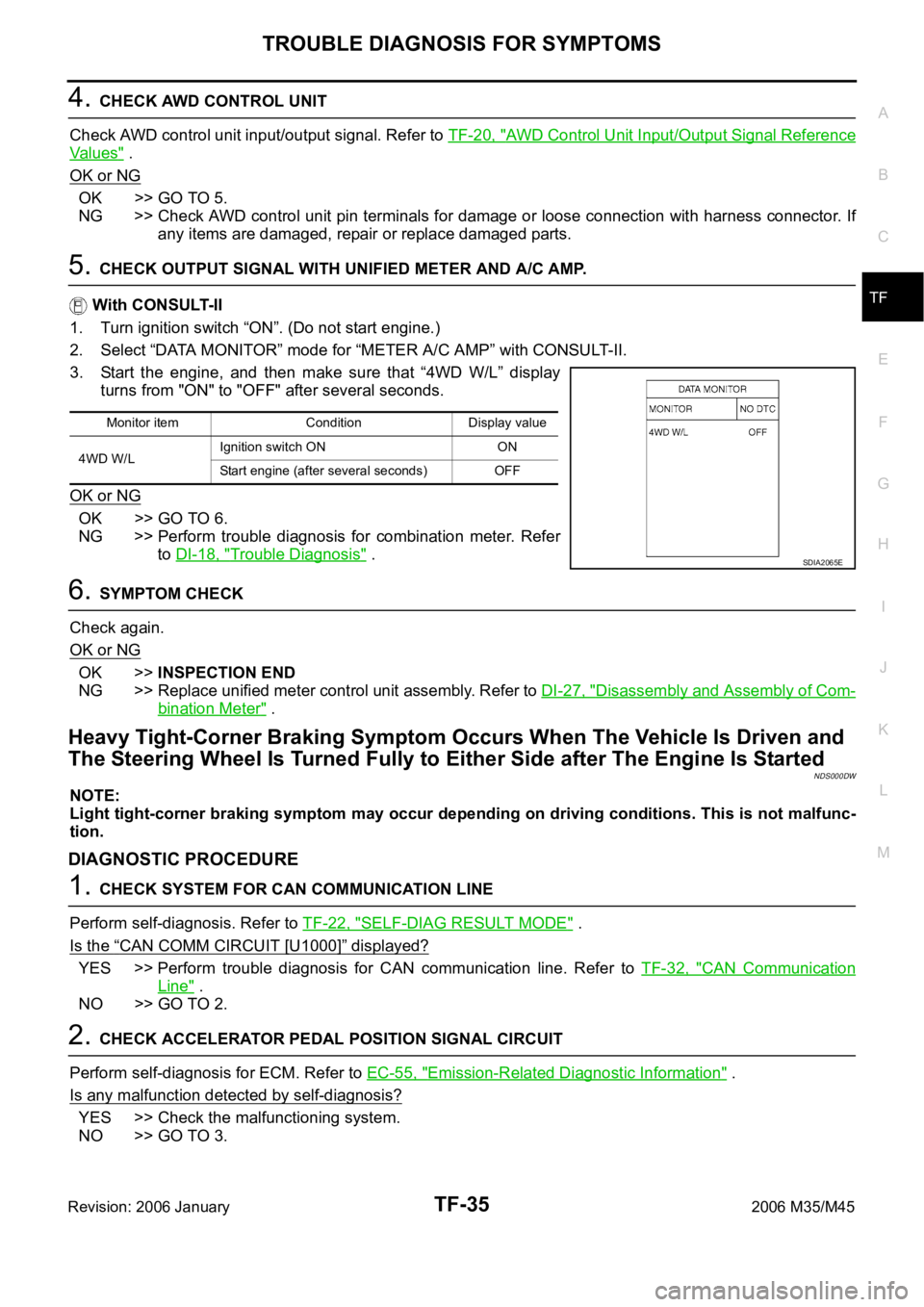
3. Start the engine, and then make sure that “4WD W/L” display
turns from "ON" to "OFF" after several seconds.
OK or NG
OK >> GO TO 4.
NG >> Perform trouble diagnosis for combination meter. Refer
to DI-18, "
Trouble Diagnosis" .
4. SYMPTOM CHECK
Check again.
OK or NG
OK >>INSPECTION END
NG >> Replace unified meter control unit assembly. Refer to DI-27, "
Disassembly and Assembly of Com-
bination Meter" .
AWD Warning Lamp Does Not Turn OFF Several Seconds after Engine StartedNDS000DV
DIAGNOSTIC PROCEDURE
1. CHECK SELF-DIAGNOSTIC RESULTS
Perform self-diagnosis. Refer to TF-22, "
SELF-DIAG RESULT MODE" .
Is any malfunction detected by self-diagnosis?
YES >> Check the malfunctioning system.
NO >> GO TO 2.
Monitor item Condition Display value
4WD W/LIgnition switch ON ON
Start engine (after several seconds) OFF
SDIA2065E
Page 5500 of 5621

TROUBLE DIAGNOSIS FOR SYMPTOMS
TF-35
C
E
F
G
H
I
J
K
L
MA
B
TF
Revision: 2006 January2006 M35/M45
4. CHECK AWD CONTROL UNIT
Check AWD control unit input/output signal. Refer to TF-20, "
AWD Control Unit Input/Output Signal Reference
Va l u e s" .
OK or NG
OK >> GO TO 5.
NG >> Check AWD control unit pin terminals for damage or loose connection with harness connector. If
any items are damaged, repair or replace damaged parts.
5. CHECK OUTPUT SIGNAL WITH UNIFIED METER AND A/C AMP.
With CONSULT-II
1. Turn ignition switch “ON”. (Do not start engine.)
2. Select “DATA MONITOR” mode for “METER A/C AMP” with CONSULT-II.
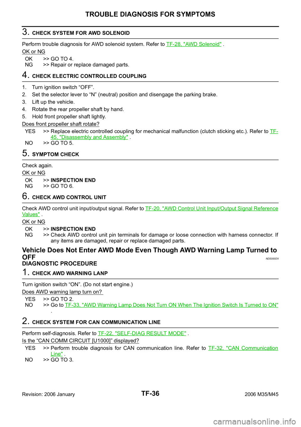
3. Start the engine, and then make sure that “4WD W/L” display
turns from "ON" to "OFF" after several seconds.
OK or NG
OK >> GO TO 6.
NG >> Perform trouble diagnosis for combination meter. Refer
to DI-18, "
Trouble Diagnosis" .
6. SYMPTOM CHECK
Check again.
OK or NG
OK >>INSPECTION END
NG >> Replace unified meter control unit assembly. Refer to DI-27, "
Disassembly and Assembly of Com-
bination Meter" .
Heavy Tight-Corner Braking Symptom Occurs When The Vehicle Is Driven and
The Steering Wheel Is Turned Fully to Either Side after The Engine Is Started
NDS000DW
NOTE:
Light tight-corner braking symptom may occur depending on driving conditions. This is not malfunc-
tion.
DIAGNOSTIC PROCEDURE
1. CHECK SYSTEM FOR CAN COMMUNICATION LINE
Perform self-diagnosis. Refer to TF-22, "
SELF-DIAG RESULT MODE" .
Is the
“CAN COMM CIRCUIT [U1000]” displayed?
YES >> Perform trouble diagnosis for CAN communication line. Refer to TF-32, "CAN Communication
Line" .
NO >> GO TO 2.
2. CHECK ACCELERATOR PEDAL POSITION SIGNAL CIRCUIT
Perform self-diagnosis for ECM. Refer to EC-55, "
Emission-Related Diagnostic Information" .
Is any malfunction detected by self-diagnosis?
YES >> Check the malfunctioning system.
NO >> GO TO 3.
Monitor item Condition Display value
4WD W/LIgnition switch ON ON
Start engine (after several seconds) OFF
SDIA2065E
Page 5501 of 5621

TF-36
TROUBLE DIAGNOSIS FOR SYMPTOMS
Revision: 2006 January2006 M35/M45
3. CHECK SYSTEM FOR AWD SOLENOID
Perform trouble diagnosis for AWD solenoid system. Refer to TF-28, "
AWD Solenoid" .
OK or NG
OK >> GO TO 4.
NG >> Repair or replace damaged parts.
4. CHECK ELECTRIC CONTROLLED COUPLING
1. Turn ignition switch “OFF”.
2. Set the selector lever to “N” (neutral) position and disengage the parking brake.
3. Lift up the vehicle.
4. Rotate the rear propeller shaft by hand.
5. Hold front propeller shaft lightly.
Does front propeller shaft rotate?
YES >> Replace electric controlled coupling for mechanical malfunction (clutch sticking etc.). Refer to TF-
45, "Disassembly and Assembly" .
NO >> GO TO 5.
5. SYMPTOM CHECK
Check again.
OK or NG
OK >>INSPECTION END
NG >> GO TO 6.
6. CHECK AWD CONTROL UNIT
Check AWD control unit input/output signal. Refer to TF-20, "
AWD Control Unit Input/Output Signal Reference
Va l u e s" .
OK or NG
OK >>INSPECTION END
NG >> Check AWD control unit pin terminals for damage or loose connection with harness connector. If
any items are damaged, repair or replace damaged parts.
Vehicle Does Not Enter AWD Mode Even Though AWD Warning Lamp Turned to
OFF
NDS000DX
DIAGNOSTIC PROCEDURE
1. CHECK AWD WARNING LANP
Turn ignition switch “ON”. (Do not start engine.)
Does AWD warning lamp turn on?
YES >> GO TO 2.
NO >> Go to TF-33, "
AWD Warning Lamp Does Not Turn ON When The Ignition Switch Is Turned to ON"
.
2. CHECK SYSTEM FOR CAN COMMUNICATION LINE
Perform self-diagnosis. Refer to TF-22, "
SELF-DIAG RESULT MODE" .
Is the
“CAN COMM CIRCUIT [U1000]” displayed?
YES >> Perform trouble diagnosis for CAN communication line. Refer to TF-32, "CAN Communication
Line" .
NO >> GO TO 3.
Page 5502 of 5621

TROUBLE DIAGNOSIS FOR SYMPTOMS
TF-37
C
E
F
G
H
I
J
K
L
MA
B
TF
Revision: 2006 January2006 M35/M45
3. CHECK AWD SOLENOID
Check AWD solenoid. Refer to TF-30, "
COMPONENT INSPECTION" .
OK or NG
OK >> GO TO 4.
NG >> Replace electric controlled coupling for malfunction of AWD solenoid. Refer to TF-45, "
Disassem-
bly and Assembly" .
4. CHECK AWD CONTROL UNIT
Check AWD control unit input/output signal. Refer to TF-20, "
AWD Control Unit Input/Output Signal Reference
Va l u e s" .
OK or NG
OK >> GO TO 5.
NG >> Check AWD control unit pin terminals for damage or loose connection with harness connector. If
any items are damaged, repair or replace damaged parts.
5. SYMPTOM CHECK
Check again.
OK or NG
OK >>INSPECTION END
NG >> Replace electric controlled coupling for mechanical malfunction (mechanical engagement of
clutch is not possible.). Refer to TF-45, "
Disassembly and Assembly" .
While Driving, AWD Warning Lamp Flashes Rapidly (When Flashing in Approx.
1 Minute and Then Turning OFF)
NDS000DY
NOTE:
Rapid flashing: 2 times/second
This symptom protects drivetrain parts when a heavy load is applied to the electric controlled coupling and
multiple disc clutch temperature increases. Also, optional distribution of torque sometimes becomes rigid
before lamp flashes rapidly. Both cases are not malfunction.
When this symptom occurs, stop vehicle and allow it to idle for some times. Flashing will stop and system will
be restored.
While Driving, AWD Warning Lamp Flashes Slowly (When Continuing to Flash
until Turning Ignition Switch OFF)
NDS000DZ
NOTE:
Slow flashing: 1 time/2 seconds
DIAGNOSTIC PROCEDURE
1. CHECK TIRE
Check the following.
Tire pressure
Wear condition
Longitudinal tire size (There is no difference between longitudinal tires.)
OK or NG
OK >> GO TO 2.
NG >> Drive at vehicle speed of 20 km/h (12 MPH) or more for 5 seconds or more after repairing or
replacing damaged parts. (Initialize improper size tire information.)
Page 5527 of 5621

WT-2Revision: 2006 January2006 M35/M45 MALFUNCTION CODE NO. 52 ........................... 34
Inspection 8: CAN Communication System Mal-
function ................................................................... 34
TROUBLE DIAGNOSIS FOR SYMPTOMS .............. 35
Inspection 1: Warning Lamp Does Not Come On
When Ignition Switch Is Turned On ........................ 35
Inspection 2: Warning Lamp Stays On When Ignition
Switch Is Turned On ............................................ ... 36
Inspection 3: Warning Lamp Blinks When Ignition
Switch Is Turned On ............................................ ... 37
Inspection 4: Turn Signal Lamp Blinks When Ignition
Switch Is Turned On ............................................ ... 37
Inspection 5: ID Registration Can Not Be Completed ... 38REMOVAL AND INSTALLATION .............................. 39
Transmitter .............................................................. 39
REMOVAL ............................................................ 39
INSTALLATION .................................................... 39
Low Tire Pressure Warning Control Unit ................. 40
REMOVAL ............................................................ 40
INSTALLATION .................................................... 40
Receiver .................................................................. 40
REMOVAL ............................................................ 40
INSTALLATION .................................................... 40
SERVICE DATA AND SPECIFICATIONS (SDS) ...... 41
Road Wheel ............................................................ 41
Tire .......................................................................... 41
Page 5535 of 5621

WT-10
LOW TIRE PRESSURE WARNING SYSTEM
Revision: 2006 January2006 M35/M45
RECEIVER
The receiver receives the air pressure signal transmitted by the transmitter in each wheel.
LOW TIRE PRESSURE WARNING CONTROL UNIT
The low tire pressure warning control unit (1) reads the air pressure
signal received by the receiver, and controls the low tire pressure
warning lamp and the buzzer operations. It also has a judgement
function to detect a system malfunction.
LOW TIRE PRESSURE WARNING LAMP
The combination meter receives tire pressure status from the low tire
pressure warning control unit using CAN communication. When a
low tire pressure condition is sensed by the low tire pressure control
unit, the combination meter low tire pressure warning lamp and
buzzer are activated.
Low Tire Pressure Warning Lamp Indication
*: Standard air pressure is for 230 kpa (2.3 kg/cm2 , 33 psi) vehicle. 1. Tire pressure receiver front 2. Tire pressure receiver rear A. Front wheel house
B. Rear wheel house
Refer to GI-11, "
Components" , for the symbols in the figure.
SEIA0649E
SEIA0650E
SEIA0434E
ConditionLow tire pressure warning
lampBuzzer
Less than 186 kPa
(1.86 kg/cm
2 , 27 psi) [Flat tire]*ON Sounds for 10 sec.
Low tire pressure warning system malfunction [Other diagnostic item]Warning lamp flashes 1 min,
then turns ONOFF
Page 5544 of 5621

TROUBLE DIAGNOSES
WT-19
C
D
F
G
H
I
J
K
L
MA
B
WT
Revision: 2006 January2006 M35/M45
ID Registration ProcedureNES000JY
ID REGISTRATION WITH ACTIVATION TOOL
This procedure must be done after replacement of a tire pressure transmitter, low tire pressure warn-
ing control unit, or tire rotation.
CAUTION:
If CONSULT-II is used with no connection of CONSULT-II CONVERTER, malfunction might be detected
during self-diagnosis depending on control unit which performs CAN communication.
1. Turn ignition switch OFF.
2. Connect CONSULT-II and CONSULT-II CONVERTER to data link connector.
3. Turn ignition switch ON.
4. Touch “START (NISSAN BASED VHCL)” “AIR PRESSURE MONITOR”.
If “AIR PRESSURE MONITOR” is not displayed, print the “SELECT SYSTEM” screen. Then refer to
LAN-7, "
Precautions When Using CONSULT-II"
NOTE:
Just after starting engine, or turning ignition switch ON, it may not be displayed even if “START (NIS-
SAN BASED VHCL)” is touched. In this case, reconnect CONSULT-II and CONSULT-II CONVERTER.
5. Touch “WORK SUPPORT” on “SELECT DIAG MODE” screen.
6. Touch “ID REGIST” on “SELECT WORK ITEM”.
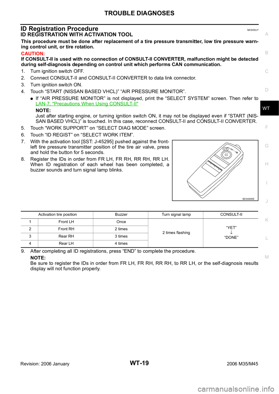
7. With the activation tool [SST: J-45295] pushed against the front-
left tire pressure transmitter position of the tire air valve, press
and hold the button for 5 seconds.
8. Register the IDs in order from FR LH, FR RH, RR RH, RR LH.
When ID registration of each wheel has been completed, a
buzzer sounds and turn signal lamp blinks.
9. After completing all ID registrations, press “END” to complete the procedure.
NOTE:
Be sure to register the IDs in order from FR LH, FR RH, RR RH, to RR LH, or the self-diagnosis results
display will not function properly.
SEIA0460E
Activation tire position Buzzer Turn signal lamp CONSULT-II
1 Front LH Once
2 times flashing“YET”
“DONE” 2 Front RH 2 times
3 Rear RH 3 times
4 Rear LH 4 times
Page 5546 of 5621
![INFINITI M35 2006 Factory Service Manual TROUBLE DIAGNOSES
WT-21
C
D
F
G
H
I
J
K
L
MA
B
WT
Revision: 2006 January2006 M35/M45
Transmitter Wake Up OperationNES000JZ
WITH TRANSMITTER ACTIVATION TOOL
1. With the activation tool [SST: J-45295] p INFINITI M35 2006 Factory Service Manual TROUBLE DIAGNOSES
WT-21
C
D
F
G
H
I
J
K
L
MA
B
WT
Revision: 2006 January2006 M35/M45
Transmitter Wake Up OperationNES000JZ
WITH TRANSMITTER ACTIVATION TOOL
1. With the activation tool [SST: J-45295] p](/img/42/57023/w960_57023-5545.png)
TROUBLE DIAGNOSES
WT-21
C
D
F
G
H
I
J
K
L
MA
B
WT
Revision: 2006 January2006 M35/M45
Transmitter Wake Up OperationNES000JZ
WITH TRANSMITTER ACTIVATION TOOL
1. With the activation tool [SST: J-45295] pushed against the front-
left transmitter, press and hold the button for 5 seconds.
When ignition switch ON, as the low tire pressure warning
lamp blinks per the follow diagram, the respective transmitter
then must be woken up.
2. Register the ID of wheel that warning lamp flashes. When wake up of registered wheel has been com-
pleted, turn signal lamp flashes two times.
3. After completing wake up all transmitters, make sure low tire pressure warning lamp goes out.
CONSULT-II Function (AIR PRESSURE MONITOR)NES000K0
FUNCTION
CONSULT-II can display each diagnosis item using the diagnosis test modes shown following.
CONSULT-II SETTING PROCEDURE
Refer to GI-39, "CONSULT-II Start Procedure" .
SEIA0460E
SEIA0378E
Mode Function Reference
WORK SUPPORTThis mode enables a technician to adjust some devices faster and
more accurately by following the indications on CONSULT-II.WT-22, "
WORK SUP-
PORT MODE"
SELF-DIAG RESULTSReceives self-diagnosis results from low tire pressure warning con-
trol unit and indicates DTCs. WT-22, "SELF-DIAG
RESULT MODE"
DATA MONITORReceives input/output signals from low tire pressure warning control
unit and indicates and stores them to facilitate locating cause of mal-
functions.WT-23, "DATA MONITOR
MODE"
CAN DIAG SUPPORT MNTR Monitors transmitting/receiving status of CAN communication.WT-12, "CAN COMMUNI-
CATION"
ACTIVE TESTDiagnostic Test Mode in with CONSULT-II drives some actuators
apart from the low tire pressure warning control unit and also shifts
some parameters in a specified range.WT-23, "ACTIVE TEST
MODE"
ECU PART NUMBER Displays low tire pressure warning control unit part number. WT-24, "
LOW TIRE PRES-
SURE WARNING CON-
TROL UNIT PART
NUMBER"