maintenance INFINITI M35 2006 Factory Manual PDF
[x] Cancel search | Manufacturer: INFINITI, Model Year: 2006, Model line: M35, Model: INFINITI M35 2006Pages: 5621, PDF Size: 65.56 MB
Page 4809 of 5621

MA-32
CHASSIS AND BODY MAINTENANCE
Revision: 2006 January2006 M35/M45
Changing Transfer FluidNLS00083
CAUTION:
When draining fluid, protect exhaust tube flange with cover.
1. Drain fluid from drain plug and refill with new gear fluid.
(For details, refer to TF-9, "
Replacement" .)
2. Check fluid level.
CAUTION:
Carefully fill the fluid. (Fill up for Approx. 3 minutes.)
Checking Propeller ShaftNLS00084
Check propeller shaft for damage, looseness or grease leakage.
Checking Differential Gear OilNLS00085
Check for oil leakage.
(For details, refer to FFD-8, "
Checking Differential Gear Oil" and
RFD-9, "
Checking Differential Gear Oil" .) Fluid grade:
Genuine NISSAN Matic D ATF (Continental U.S.
and Alaska) or Canada NISSAN Automatic Trans-
mission Fluid
Refer to MA-12, "
RECOMMENDED FLUIDS AND
LUBRICANTS" .
Fluid capacity:
: Approx. 1.25 (2-5/8 US pt, 2-1/4 lmp pt)
Drain plug:
: 29.4 Nꞏm (3.0 kg-m, 22 ft-lb)
Filler plug:
: 35 Nꞏm (3.6 kg-m, 26 ft-lb)SDIA2087E
Tightening torque:
Refer to PR-6, "
REAR PROPELLER SHAFT"
SMA118A
SMA012C
Page 4810 of 5621

CHASSIS AND BODY MAINTENANCE
MA-33
C
D
E
F
G
H
I
J
K
MA
B
MA
Revision: 2006 January2006 M35/M45
Changing Differential Gear OilNLS00086
1. Drain oil from drain plug and refill with new gear oil.
(For details, refer to FFD-8, "
Changing Differential Gear Oil" and RFD-9, "Changing Differential Gear Oil"
.)
2. Check oil level.
Balancing Wheels (Bonding Weight Type)NLS00087
REMOVAL
1. Remove inner and outer balance weights from the road wheel.
CAUTION:
Be careful not to scratch the road wheel during removal.
2. Using releasing agent, remove double-faced adhesive tape from the road wheel.
CAUTION:
Be careful not to scratch the road wheel during removal.
After removing double-faced adhesive tape, wipe clean traces of releasing agent from the road
wheel.
WHEEL BALANCE ADJUSTMENT
If a tire balance machine has adhesion balance weight mode settings and drive-in weight mode setting,
select and adjust a drive-in weight mode suitable for road wheels.
1. Set road wheel on wheel balancer using the center hole as a guide. Start the tire balance machine.
2. When inner and outer unbalance values are shown on the wheel balancer indicator, multiply outer unbal-
ance value by 5/3 to determine balance weight that should be used. Select the outer balance weight with
a value closest to the calculated value above and install it to the designated outer position of, or at the
designated angle in relation to the road wheel.
CAUTION:
Do not install the inner balance weight before installing the outer balance weight. Oil grade and Viscosity:
Refer to MA-12, "
RECOMMENDED FLUIDS
AND LUBRICANTS" .
Capacity:
Front final drive (F160A)
0.65 (1 - 3/8 US pt, 1 - 1/8 lmp pt)
Rear final drive (R200)
1.4 (3 US pt, 2 - 1/2 lmp pt)
Filler plug:
Front final drive
: 34.5 N-m (3.5 kg-m, 25 ft-lb)
Rear final drive
: 34.5 N-m (3.5 kg-m, 25 ft-lb)
Drain plug:
Front final drive
: 34.5 N-m (3.5 kg-m, 25 ft-lb)
Rear final drive
: 34.5 N-m (3.5 kg-m, 25 ft-lb)
SDIA1151E
Page 4811 of 5621
MA-34
CHASSIS AND BODY MAINTENANCE
Revision: 2006 January2006 M35/M45
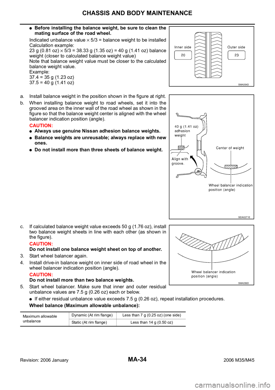
Before installing the balance weight, be sure to clean the
mating surface of the road wheel.
Indicated unbalance value
5/3 = balance weight to be installed
Calculation example:
23 g (0.81 oz)
5/3 = 38.33 g (1.35 oz) = 40 g (1.41 oz) balance
weight (closer to calculated balance weight value)
Note that balance weight value must be closer to the calculated
balance weight value.
Example:
37.4 = 35 g (1.23 oz)
37.5 = 40 g (1.41 oz)
a. Install balance weight in the position shown in the figure at right.
b. When installing balance weight to road wheels, set it into the
grooved area on the inner wall of the road wheel as shown in the
figure so that the balance weight center is aligned with the wheel
balancer indication position (angle).
CAUTION:
Always use genuine Nissan adhesion balance weights.
Balance weights are unreusable; always replace with new
ones.
Do not install more than three sheets of balance weight.
c. If calculated balance weight value exceeds 50 g (1.76 oz), install
two balance weight sheets in line with each other (as shown in
the figure).
CAUTION:
Do not install one balance weight sheet on top of another.
3. Start wheel balancer again.
4. Install drive-in balance weight on inner side of road wheel in the
wheel balancer indication position (angle).
CAUTION:
Do not install more than two balance weights.
5. Start wheel balancer. Make sure that inner and outer residual
unbalance values are 7.5 g (0.26 oz) each or below.
If either residual unbalance value exceeds 7.5 g (0.26 oz), repeat installation procedures.
Wheel balance (Maximum allowable unbalance):
SMA054D
SEIA0271E
Maximum allowable
unbalanceDynamic (At rim flange) Less than 7 g (0.25 oz) (one side)
Static (At rim flange) Less than 14 g (0.50 oz)
SMA056D
Page 4812 of 5621
CHASSIS AND BODY MAINTENANCE
MA-35
C
D
E
F
G
H
I
J
K
MA
B
MA
Revision: 2006 January2006 M35/M45
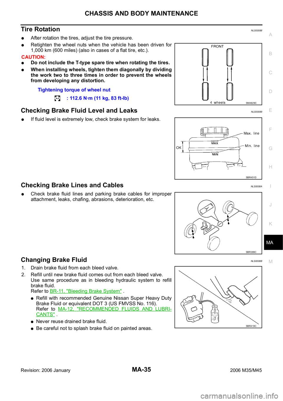
Tire RotationNLS00088
After rotation the tires, adjust the tire pressure.
Retighten the wheel nuts when the vehicle has been driven for
1,000 km (600 miles) (also in cases of a flat tire, etc.).
CAUTION:
Do not include the T-type spare tire when rotating the tires.
When installing wheels, tighten them diagonally by dividing
the work two to three times in order to prevent the wheels
from developing any distortion.
Checking Brake Fluid Level and LeaksNLS00089
If fluid level is extremely low, check brake system for leaks.
Checking Brake Lines and CablesNLS0008A
Check brake fluid lines and parking brake cables for improper
attachment, leaks, chafing, abrasions, deterioration, etc.
Changing Brake FluidNLS0008B
1. Drain brake fluid from each bleed valve.
2. Refill until new brake fluid comes out from each bleed valve.
Use same procedure as in bleeding hydraulic system to refill
brake fluid.
Refer to BR-11, "
Bleeding Brake System" .
Refill with recommended Genuine Nissan Super Heavy Duty
Brake Fluid or equivalent DOT 3 (US FMVSS No. 116).
Refer to MA-12, "
RECOMMENDED FLUIDS AND LUBRI-
CANTS" .
Never reuse drained brake fluid.
Be careful not to splash brake fluid on painted areas.Tightening torque of wheel nut
: 112.6 Nꞏm (11 kg, 83 ft-lb)
SMA829C
SBR451D
SBR389C
SBR419C
Page 4813 of 5621
MA-36
CHASSIS AND BODY MAINTENANCE
Revision: 2006 January2006 M35/M45
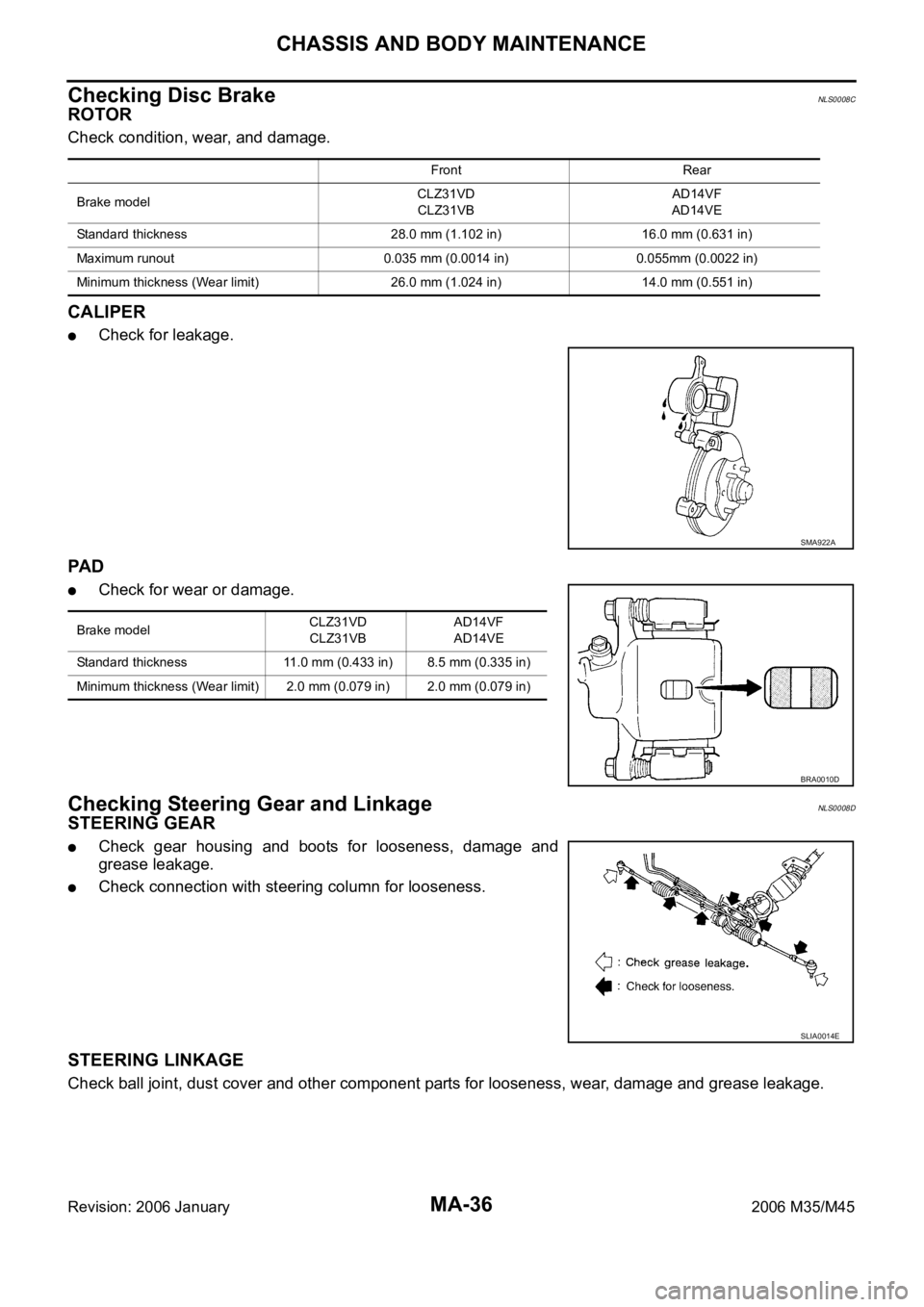
Checking Disc BrakeNLS0008C
ROTOR
Check condition, wear, and damage.
CALIPER
Check for leakage.
PA D
Check for wear or damage.
Checking Steering Gear and LinkageNLS0008D
STEERING GEAR
Check gear housing and boots for looseness, damage and
grease leakage.
Check connection with steering column for looseness.
STEERING LINKAGE
Check ball joint, dust cover and other component parts for looseness, wear, damage and grease leakage.
Front Rear
Brake modelCLZ31VD
CLZ31VBAD14VF
AD14VE
Standard thickness 28.0 mm (1.102 in) 16.0 mm (0.631 in)
Maximum runout 0.035 mm (0.0014 in) 0.055mm (0.0022 in)
Minimum thickness (Wear limit) 26.0 mm (1.024 in) 14.0 mm (0.551 in)
SMA922A
Brake modelCLZ31VD
CLZ31VBAD14VF
AD14VE
Standard thickness 11.0 mm (0.433 in) 8.5 mm (0.335 in)
Minimum thickness (Wear limit) 2.0 mm (0.079 in) 2.0 mm (0.079 in)
BRA0010D
SLIA0014E
Page 4814 of 5621
CHASSIS AND BODY MAINTENANCE
MA-37
C
D
E
F
G
H
I
J
K
MA
B
MA
Revision: 2006 January2006 M35/M45
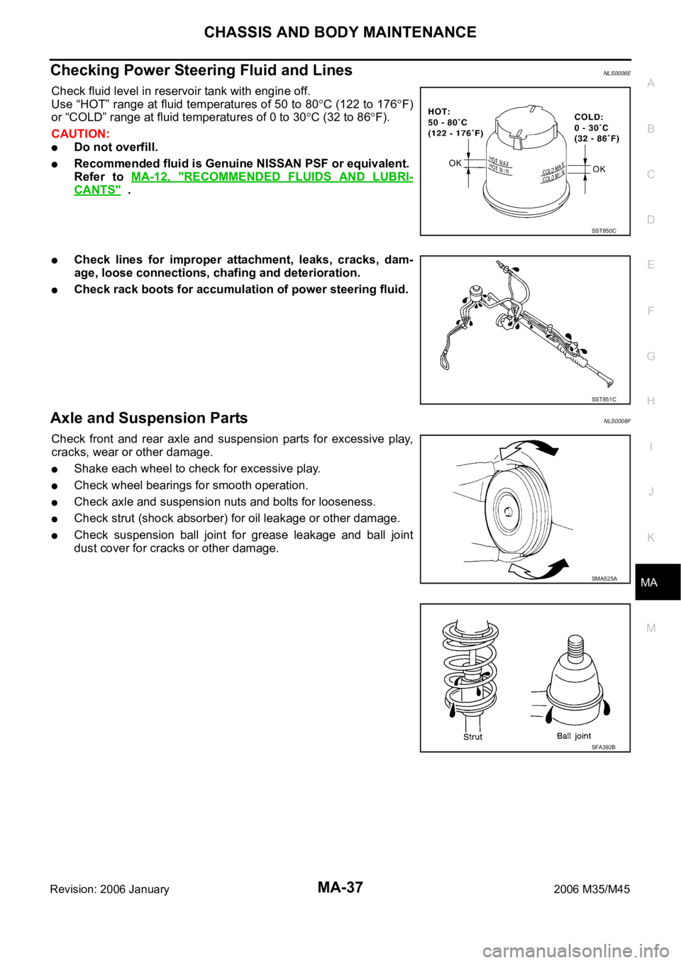
Checking Power Steering Fluid and LinesNLS0008E
Check fluid level in reservoir tank with engine off.
Use “HOT” range at fluid temperatures of 50 to 80
C (122 to 176F)
or “COLD” range at fluid temperatures of 0 to 30
C (32 to 86F).
CAUTION:
Do not overfill.
Recommended fluid is Genuine NISSAN PSF or equivalent.
Refer to MA-12, "
RECOMMENDED FLUIDS AND LUBRI-
CANTS" .
Check lines for improper attachment, leaks, cracks, dam-
age, loose connections, chafing and deterioration.
Check rack boots for accumulation of power steering fluid.
Axle and Suspension PartsNLS0008F
Check front and rear axle and suspension parts for excessive play,
cracks, wear or other damage.
Shake each wheel to check for excessive play.
Check wheel bearings for smooth operation.
Check axle and suspension nuts and bolts for looseness.
Check strut (shock absorber) for oil leakage or other damage.
Check suspension ball joint for grease leakage and ball joint
dust cover for cracks or other damage.
SST850C
SST851C
SMA525A
SFA392B
Page 4815 of 5621
MA-38
CHASSIS AND BODY MAINTENANCE
Revision: 2006 January2006 M35/M45
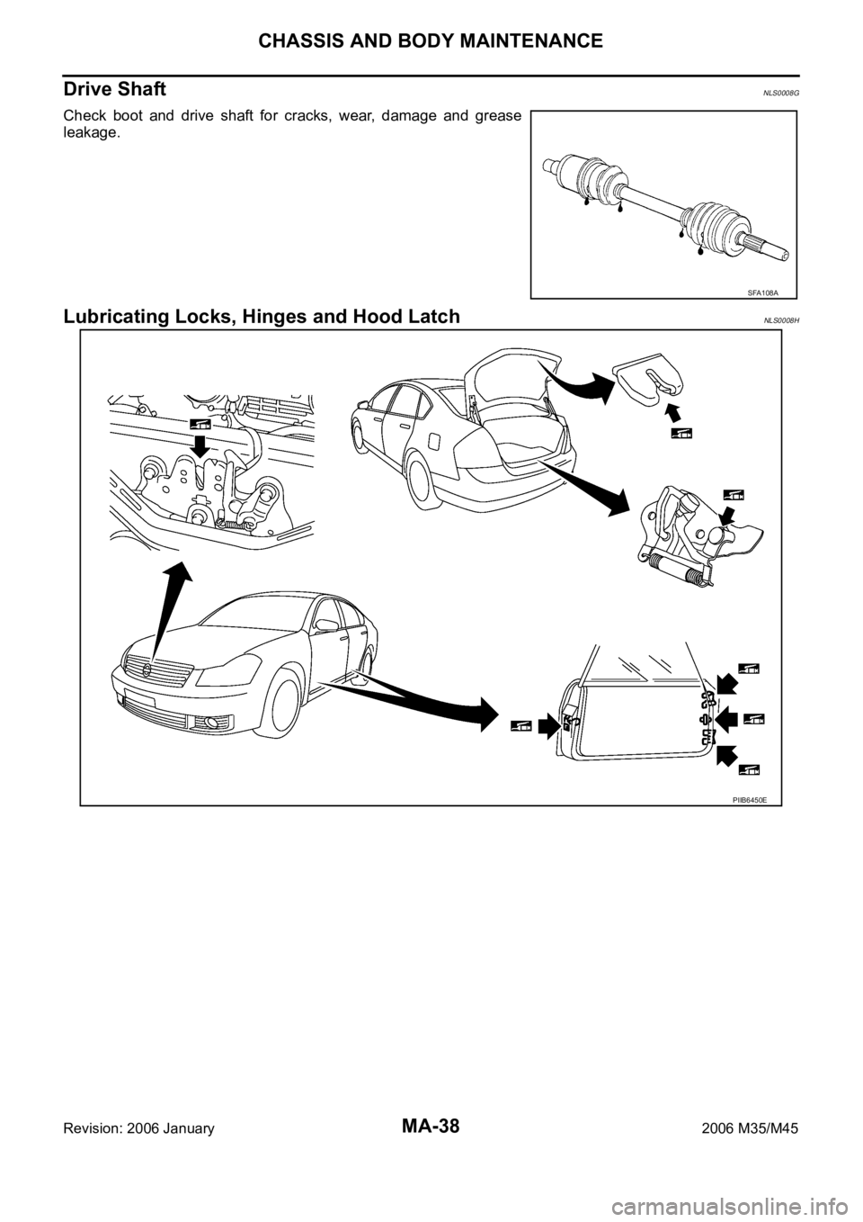
Drive ShaftNLS0008G
Check boot and drive shaft for cracks, wear, damage and grease
leakage.
Lubricating Locks, Hinges and Hood LatchNLS0008H
SFA108A
PIIB6450E
Page 4816 of 5621
CHASSIS AND BODY MAINTENANCE
MA-39
C
D
E
F
G
H
I
J
K
MA
B
MA
Revision: 2006 January2006 M35/M45
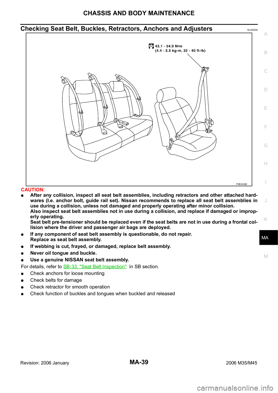
Checking Seat Belt, Buckles, Retractors, Anchors and AdjustersNLS0008I
CAUTION:
After any collision, inspect all seat belt assemblies, including retractors and other attached hard-
wares (I.e. anchor bolt, guide rail set). Nissan recommends to replace all seat belt assemblies in
use during a collision, unless not damaged and properly operating after minor collision.
Also inspect seat belt assemblies not in use during a collision, and replace if damaged or improp-
erly operating.
Seat belt pre-tensioner should be replaced even if the seat belts are not in use during a frontal col-
lision where the driver and passenger air bags are deployed.
If any component of seat belt assembly is questionable, do not repair.
Replace as seat belt assembly.
If webbing is cut, frayed, or damaged, replace belt assembly.
Never oil tongue and buckle.
Use a genuine NISSAN seat belt assembly.
For details, refer to SB-33, "
Seat Belt Inspection" in SB section.
Check anchors for loose mounting
Check belts for damage
Check retractor for smooth operation
Check function of buckles and tongues when buckled and released
PIIB3436E
Page 4956 of 5621

PRECAUTIONS
PS-3
C
D
E
F
H
I
J
K
L
MA
B
PS
Revision: 2006 January2006 M35/M45
PRECAUTIONSPFP:00001
Precautions for Supplemental Restraint System (SRS) “AIR BAG” and “SEAT
BELT PRE-TENSIONER”
NGS000CZ
The Supplemental Restraint System such as “AIR BAG” and “SEAT BELT PRE-TENSIONER”, used along
with a front seat belt, helps to reduce the risk or severity of injury to the driver and front passenger for certain
types of collision. This system includes seat belt switch inputs and dual stage front air bag modules. The SRS
system uses the seat belt switches to determine the front air bag deployment, and may only deploy one front
air bag, depending on the severity of a collision and whether the front occupants are belted or unbelted.
Information necessary to service the system safely is included in the SRS and SB section of this Service Man-
ual.
WAR NING :
To avoid rendering the SRS inoperative, which could increase the risk of personal injury or death
in the event of a collision which would result in air bag inflation, all maintenance must be per-
formed by an authorized NISSAN/INFINITI dealer.
Improper maintenance, including incorrect removal and installation of the SRS, can lead to per-
sonal injury caused by unintentional activation of the system. For removal of Spiral Cable and Air
Bag Module, see the SRS section.
Do not use electrical test equipment on any circuit related to the SRS unless instructed to in this
Service Manual. SRS wiring harnesses can be identified by yellow and/or orange harnesses or
harness connectors.
Precautions Necessary for Steering Wheel Rotation after Battery DisconnectNGS000D0
NOTE:
Before removing and installing any control units, first turn the push-button ignition switch to the LOCK
position, then disconnect both battery cables.
After finishing work, confirm that all control unit connectors are connected properly, then re-connect both
battery cables.
Always use CONSULT-II to perform self-diagnosis as a part of each function inspection after finishing
work. If a DTC is detected, perform trouble diagnosis according to self-diagnosis results.
This vehicle is equipped with a push-button ignition switch and a steering lock unit.
If the battery is disconnected or discharged, the steering wheel will lock and cannot be turned.
If turning the steering wheel is required with the battery disconnected or discharged, follow the procedure
below before starting the repair operation.
OPERATION PROCEDURE
1. Connect both battery cables.
NOTE:
Supply power using jumper cables if battery is discharged.
2. Carry the Intelligent Key or insert it to the key slot and turn the push-button ignition switch to ACC position.
(At this time, the steering lock will be released.)
3. Disconnect both battery cables. The steering lock will remain released with both battery cables discon-
nected and the steering wheel can be turned.
4. Perform the necessary repair operation.
5. When the repair work is completed, re-connect both battery cables. With the brake pedal released, turn
the push-button ignition switch from ACC position to ON position, then to LOCK position. (The steering
wheel will lock when the push-button ignition switch is turned to LOCK position.)
6. Perform self-diagnosis check of all control units using CONSULT-II.
Page 5015 of 5621

RF-2
PRECAUTIONS
Revision: 2006 January2006 M35/M45
PRECAUTIONSPFP:00001
Precautions for Supplemental Restraint System (SRS) “AIR BAG” and “SEAT
BELT PRE-TENSIONER”
NIS0023J
The Supplemental Restraint System such as “AIR BAG” and “SEAT BELT PRE-TENSIONER”, used along
with a front seat belt, helps to reduce the risk or severity of injury to the driver and front passenger for certain
types of collision. This system includes seat belt switch inputs and dual stage front air bag modules. The SRS
system uses the seat belt switches to determine the front air bag deployment, and may only deploy one front
air bag, depending on the severity of a collision and whether the front occupants are belted or unbelted.
Information necessary to service the system safely is included in the SRS and SB section of this Service Man-
ual.
WAR NING :
To avoid rendering the SRS inoperative, which could increase the risk of personal injury or death
in the event of a collision which would result in air bag inflation, all maintenance must be per-
formed by an authorized NISSAN/INFINITI dealer.
Improper maintenance, including incorrect removal and installation of the SRS, can lead to per-
sonal injury caused by unintentional activation of the system. For removal of Spiral Cable and Air
Bag Module, see the SRS section.
Do not use electrical test equipment on any circuit related to the SRS unless instructed to in this
Service Manual. SRS wiring harnesses can be identified by yellow and/or orange harnesses or
harness connectors.
Precautions NIS0023K
Disconnect both battery cables in advance.
Disconnect air bag system line in advance.
Do not tamper with or force air bag lid open, as this may adversely affect air bag performance.
Be careful not to scratch pad and other parts.
When removing or disassembling any part, be careful not to damage or deform it. Protect parts, which
may get in the way with cloth.
When removing parts with a screwdriver or other tool, protect parts by wrapping them with vinyl or tape.
Keep removed parts protected with cloth.
If a clip is deformed or damaged, replace it.
If an unreusable part is removed, replace it with a new one.
Tighten bolts and nuts firmly to the specified torque.
After re-assembly has been completed, make sure each part functions correctly.
Remove stains in the following way.
Water-soluble stains:
Dip a soft cloth in warm water, and then squeeze it tightly. After wiping the stain, wipe with a soft dry cloth.
Oil stain:
Dissolve a synthetic detergent in warm water (density of 2 to 3% or less), dip the cloth, then clean off the stain
with the cloth. Next, dip the cloth in fresh water and squeeze it tightly. Then clean off the detergent completely.
Then wipe the area with a soft dry cloth.
Do not use any organic solvent, such as thinner or benzine.