checking brake fluid INFINITI M35 2006 Factory Service Manual
[x] Cancel search | Manufacturer: INFINITI, Model Year: 2006, Model line: M35, Model: INFINITI M35 2006Pages: 5621, PDF Size: 65.56 MB
Page 80 of 5621
AT-1
AUTOMATIC TRANSMISSION
C TRANSMISSION/TRANSAXLE
CONTENTS
D
E
F
G
H
I
J
K
L
M
SECTION AT
A
B
AT
Revision: 2006 January2006 M35/M45
AUTOMATIC TRANSMISSION
INDEX FOR DTC ........................................................ 5
Alphabetical Index .................................................... 5
DTC No. Index ......................................................... 6
PRECAUTIONS .......................................................... 7
Precautions for Supplemental Restraint System
(SRS) “AIR BAG” and “SEAT BELT PRE-TEN-
SIONER” .................................................................. 7
Precautions for On Board Diagnostic (OBD) System
of A/T and Engine .................................................... 7
Precautions .............................................................. 8
Service Notice or Precautions .................................. 9
PREPARATION ......................................................... 10
Special Service Tools ............................................. 10
Commercial Service Tools ....................................... 11
A/T FLUID ................................................................. 12
Changing A/T Fluid .............................................
... 12
Checking A/T Fluid ................................................. 13
A/T Fluid Cooler Cleaning ...................................... 14
A/T CONTROL SYSTEM .......................................... 17
Cross-Sectional View (VQ35DE Models for 2WD) ... 17
Cross-Sectional View (VK45DE Models for 2WD) ... 18
Cross-Sectional View (AWD Models) ..................... 19
Shift Mechanism ..................................................... 20
TCM Function ......................................................... 31
CAN Communication .............................................. 32
Input/Output Signal of TCM .................................... 32
Line Pressure Control ............................................ 33
Shift Control ........................................................... 34
Lock-up Control ...................................................... 37
Engine Brake Control ............................................. 38
Control Valve .......................................................... 38
ON BOARD DIAGNOSTIC (OBD) SYSTEM ............ 40
Introduction ............................................................ 40
OBD-II Function for A/T System ............................. 40
One or Two Trip Detection Logic of OBD-II ............ 40
OBD-II Diagnostic Trouble Code (DTC) ................. 40
Malfunction Indicator Lamp (MIL) ........................... 43
TROUBLE DIAGNOSIS ............................................ 44
DTC Inspection Priority Chart ................................ 44
Fail-safe ................................................................. 44How to Perform Trouble Diagnosis for Quick and
Accurate Repair ...................................................... 46
A/T Electrical Parts Location .................................. 51
Circuit Diagram ....................................................... 52
Inspections before Trouble Diagnosis .................... 53
Check before Engine Is Started .............................. 57
Check at Idle ........................................................... 57
Cruise Test - Part 1 ................................................. 59
Cruise Test - Part 2 ................................................. 61
Cruise Test - Part 3 ................................................. 62
Vehicle Speed at Which Gear Shifting Occurs ....... 63
Vehicle Speed at Which Lock-Up Occurs/Releases ... 63
Symptom Chart ....................................................... 64
TCM Input/Output Signal Reference Values ........... 89
CONSULT-II Function (A/T) .................................... 90
Diagnostic Procedure without CONSULT-II ..........103
DTC U1000 CAN COMMUNICATION LINE ............105
Description ............................................................105
On Board Diagnosis Logic ....................................105
Possible Cause .....................................................105
DTC Confirmation Procedure ...............................105
Wiring Diagram — AT — CAN ..............................106
Diagnostic Procedure ...........................................107
DTC P0615 START SIGNAL CIRCUIT ...................108
Description ............................................................108
CONSULT-II Reference Value ..............................108
On Board Diagnosis Logic ....................................108
Possible Cause .....................................................108
DTC Confirmation Procedure ...............................108
Wiring Diagram — AT — STSIG ..........................109
Diagnostic Procedure ...........................................110
DTC P0700 TCM .....................................................112
Description ............................................................112
On Board Diagnosis Logic ....................................112
Possible Cause .....................................................112
DTC Confirmation Procedure ...............................112
Diagnostic Procedure ...........................................112
DTC P0705 PARK/NEUTRAL POSITION SWITCH .113
Description ............................................................113
CONSULT-II Reference Value ..............................113
Page 83 of 5621

AT-4Revision: 2006 January2006 M35/M45 A/T Does Not Shift: 4th Gear
3rd Gear ............215
A/T Does Not Shift: 3rd Gear
2nd Gear ...........217
A/T Does Not Shift: 2nd Gear
1st Gear ............218
Vehicle Does Not Decelerate by Engine Brake ....220
SHIFT CONTROL SYSTEM ....................................222
Control Device Removal and Installation ..............222
Control Rod Removal and Installation ..................226
Adjustment of A/T Position ...................................227
Checking of A/T Position ......................................228
A/T SHIFT LOCK SYSTEM .....................................229
Description ............................................................229
Shift Lock System Electrical Parts Location .........229
Wiring Diagram — AT — SHIFT ...........................230
Diagnostic Procedure ...........................................232
ON-VEHICLE SERVICE ..........................................236
C o n t r o l V a l v e W i t h T C M a n d A / T F l u i d Te m p e r a t u r e
Sensor 2 ...............................................................236
Parking Components (2WD Models Only) ............248
Rear Oil Seal (VQ35DE Models Only) ..................260
Revolution Sensor Components (2WD Models
Only) .....................................................................261
AIR BREATHER HOSE ...........................................269
Removal and Installation ......................................269
TRANSMISSION ASSEMBLY ................................271
Removal and Installation (2WD Models) ..............271
Removal and Installation (AWD Models) ..............275
OVERHAUL .............................................................278
Components .........................................................278Oil Channel ...........................................................292
Locations of Adjusting Shims, Needle Bearings,
Thrust Washers and Snap Rings ..........................295
DISASSEMBLY .......................................................298
Disassembly ..........................................................298
REPAIR FOR COMPONENT PARTS ......................318
Oil Pump ...............................................................318
Front Sun Gear, 3rd One-Way Clutch ...................321
Front Carrier, Input Clutch, Rear Internal Gear .....323
Mid Sun Gear, Rear Sun Gear, High and Low
Reverse Clutch Hub ..............................................329
High and Low Reverse Clutch ..............................335
Direct Clutch .........................................................337
ASSEMBLY .............................................................340
Assembly (1) .........................................................340
Adjustment ............................................................356
Assembly (2) .........................................................358
SERVICE DATA AND SPECIFICATIONS (SDS) ....365
General Specifications ......................................... .365
Vehicle Speed at Which Gear Shifting Occurs ......365
Vehicle Speed at Which Lock-Up Occurs/Releases .366
Stall Speed ............................................................366
Line Pressure ........................................................366
A/T Fluid Temperature Sensor ..............................366
Turbine Revolution Sensor ....................................367
Vehicle Speed Sensor A/T (Revolution Sensor) ...367
Reverse Brake ......................................................367
Total End Play .......................................................367
Page 92 of 5621
A/T FLUID
AT-13
D
E
F
G
H
I
J
K
L
MA
B
AT
Revision: 2006 January2006 M35/M45
Checking A/T FluidNCS001JJ
1. Warm up engine.
2. Check for A/T fluid leakage.
3. Loosen the level gauge bolt.
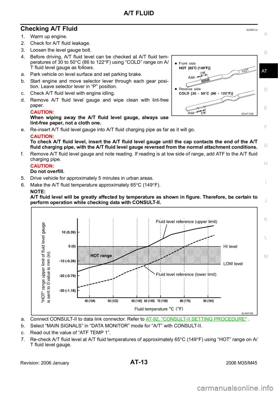
4. Before driving, A/T fluid level can be checked at A/T fluid tem-
peratures of 30 to 50
C (86 to 122F) using “COLD” range on A/
T fluid level gauge as follows.
a. Park vehicle on level surface and set parking brake.
b. Start engine and move selector lever through each gear posi-
tion. Leave selector lever in “P” position.
c. Check A/T fluid level with engine idling.
d. Remove A/T fluid level gauge and wipe clean with lint-free
paper.
CAUTION:
When wiping away the A/T fluid level gauge, always use
lint-free paper, not a cloth one.
e. Re-insert A/T fluid level gauge into A/T fluid charging pipe as far as it will go.
CAUTION:
To check A/T fluid level, insert the A/T fluid level gauge until the cap contacts the end of the A/T
fluid charging pipe, with the A/T fluid level gauge reversed from the normal attachment conditions.
f. Remove A/T fluid level gauge and note reading. If reading is at low side of range, add ATF to the A/T fluid
charging pipe.
CAUTION:
Do not overfill.
5. Drive vehicle for approximately 5 minutes in urban areas.
6. Make the A/T fluid temperature approximately 65
C (149F).
NOTE:
A/T fluid level will be greatly affected by temperature as shown in figure. Therefore, be certain to
perform operation while checking data with CONSULT-II.
a. Connect CONSULT-II to data link connector. Refer to AT- 9 2 , "
CONSULT-II SETTING PROCEDURE" .
b. Select “MAIN SIGNALS” in “DATA MONITOR” mode for “A/T” with CONSULT-II.
c. Read out the value of “ATF TEMP 1”.
7. Re-check A/T fluid level at A/T fluid temperatures of approximately 65
C (149F) using “HOT” range on A/
T fluid level gauge.
SCIA7120E
SLIA0016E
Page 132 of 5621

TROUBLE DIAGNOSIS
AT-53
D
E
F
G
H
I
J
K
L
MA
B
AT
Revision: 2006 January2006 M35/M45
Inspections before Trouble DiagnosisNCS001K7
A/T FLUID CHECK
A/T Fluid Leakage and A/T Fluid Level Check
Inspect for A/T fluid leakage and check the A/T fluid level. Refer to AT- 1 3 , "Checking A/T Fluid" .
A/T Fluid Condition Check
Inspect the A/T fluid condition.
STALL TEST
Stall Test Procedure
1. Inspect the amount of engine oil. Replenish the engine oil if necessary.
2. Drive for about 10 minutes to warm up the vehicle so that the A/
T fluid temperature is 50 to 80
C (122 to 176F). Inspect the
amount of ATF. Replenish if necessary.
3. Securely engage the parking brake so that the tires do not turn.
4. Engine start, apply foot brake, and place selector lever in “D”
position.
Fluid condition Conceivable Cause Required Operation
Varnished (viscous
varnish state)Clutch, brake
scorchedReplace the ATF and check the A/T
main unit and the vehicle for mal-
functions (wire harnesses, cooler
pipes, etc.)
Milky white or cloudy Water in the fluidReplace the ATF and check for
places where water is getting in.
Large amount of metal
powder mixed inUnusual wear of
sliding parts within
A/TReplace the ATF and check for
improper operation of the A/T.
SAT638A
SAT647B
SCIA7463E
SCIA6787E
Page 274 of 5621

TROUBLE DIAGNOSIS FOR SYMPTOMS
AT-195
D
E
F
G
H
I
J
K
L
MA
B
AT
Revision: 2006 January2006 M35/M45
Vehicle Does Not Creep Backward in “R” PositionNCS001Q4
SYMPTOM:
The vehicle does not creep in “R” position. Or an extreme lack of acceleration is observed.
DIAGNOSTIC PROCEDURE
1. CHECK SELF-DIAGNOSTIC RESULTS
Perform self-diagnosis. Refer to AT- 9 2 , "
SELF-DIAGNOSTIC RESULT MODE" , AT- 1 0 3 , "TCM SELF-DIAG-
NOSTIC PROCEDURE (NO TOOLS)" .
Is any malfunction detected by self-diagnosis results?
YES >> Check malfunctioning system. Refer to AT- 9 2 , "SELF-DIAGNOSTIC RESULT MODE" , AT- 1 0 4 ,
"Judgement Self-diagnosis Code" .
NO >> GO TO 2.
2. CHECK CONTROL LINKAGE
Check control linkage.
Refer to AT-228, "Checking of A/T Position" .
OK or NG
OK >> GO TO 3.
NG >> Adjust control linkage. Refer to AT-227, "
Adjustment of A/T Position" .
3. CHECK A/T FLUID LEVEL
Check A/T fluid level. Refer to AT- 1 3 , "
Checking A/T Fluid" .
OK or NG
OK >> GO TO 4.
NG >> Refill ATF.
4. CHECK STALL TEST
Check stall revolution with selector lever in “M” and “R” positions.
Refer to AT- 5 3 , "
STALL TEST" .
OK or NG
OK >> GO TO 6.
OK in “M” position, NG in “R” position>>GO TO 5
NG in both “M” and “R” positions>>GO TO 8.
5. DETECT MALFUNCTIONING ITEM
1. Disassemble A/T. Refer to AT-298, "
DISASSEMBLY" .
2. Check the following.
–Reverse brake. Refer to AT-298, "DISASSEMBLY" .
OK or NG
OK >> GO TO 9.
NG >> Repair or replace damaged parts.
6. CHECK LINE PRESSURE
Check line pressure with the engine idling. Refer to AT- 5 5 , "
LINE PRESSURE TEST" .
OK or NG
OK >> GO TO 9.
NG - 1 >> Line pressure high: GO TO 7.
NG - 2 >> Line pressure low: GO TO 8.
Page 299 of 5621
AT-220
TROUBLE DIAGNOSIS FOR SYMPTOMS
Revision: 2006 January2006 M35/M45
Vehicle Does Not Decelerate by Engine BrakeNCS001QK
SYMPTOM:
No engine brake is applied when the gear is shifted from the 2nd to 1st gear.
DIAGNOSTIC PROCEDURE
1. CHECK SELF-DIAGNOSTIC RESULTS
Perform self-diagnosis. Refer to AT- 9 2 , "
SELF-DIAGNOSTIC RESULT MODE" , AT- 1 0 3 , "TCM SELF-DIAG-
NOSTIC PROCEDURE (NO TOOLS)" .
Is any malfunction detected by self-diagnostic results?
YES >> Check malfunctioning system. Refer to AT- 9 2 , "SELF-DIAGNOSTIC RESULT MODE" , AT- 1 0 4 ,
"Judgement Self-diagnosis Code" .
NO >> GO TO 2.
2. CHECK A/T FLUID LEVEL
Check A/T fluid level. Refer to AT-13, "
Checking A/T Fluid" .
OK or NG
OK >> GO TO 3.
NG >> Refill ATF.
3. CHECK CONTROL LINKAGE
Check control linkage.
Refer to AT-228, "Checking of A/T Position" .
OK or NG
OK >> GO TO 4.
NG >> Adjust control linkage. Refer to AT-227, "
Adjustment of A/T Position" .
4. CHECK MANUAL MODE SWITCH
Check manual mode switch. Refer to AT-167, "
DTC P1815 MANUAL MODE SWITCH" .
OK or NG
OK >> GO TO 5.
NG >> Repair or replace damaged parts.
5. CHECK A/T FLUID CONDITION
1. Remove oil pan. Refer to AT-236, "
Control Valve With TCM and A/T Fluid Temperature Sensor 2" .
2. Check A/T fluid condition. Refer to AT- 5 3 , "
A/T Fluid Condition Check" .
OK or NG
OK >> GO TO 6.
NG >> GO TO 9.
6. DETECT MALFUNCTIONING ITEM
Check malfunction items. If any items are damaged, repair or replace damaged parts. Refer to AT- 6 4 ,
"Symptom Chart" (Symptom No.58).
OK or NG
OK >> GO TO 7.
NG >> Repair or replace damaged parts.
Page 1276 of 5621
BR-1
BRAKE SYSTEM
F BRAKES
CONTENTS
C
D
E
G
H
I
J
K
L
M
SECTION BR
A
B
BR
Revision: 2006 January2006 M35/M45
BRAKE SYSTEM
PRECAUTIONS .......................................................... 3
Precautions for Supplemental Restraint System
(SRS) “AIR BAG” and “SEAT BELT PRE-TEN-
SIONER” .................................................................. 3
Precautions for Procedures without Cowl Top Cover ..... 3
Precautions for Brake System .................................. 3
PREPARATION ........................................................... 4
Commercial Service Tools ........................................ 4
NOISE, VIBRATION AND HARSHNESS (NVH)
TROUBLESHOOTING ................................................ 5
NVH Troubleshooting Chart ..................................... 5
BRAKE PEDAL .......................................................... 6
Inspection and Adjustment ....................................... 6
ADJUSTMENT ...................................................... 7
Removal and Installation .......................................... 7
COMPONENTS .................................................... 7
REMOVAL ........................................................
..... 8
INSPECTION AFTER REMOVAL ......................... 8
INSTALLATION ..................................................... 9
BRAKE FLUID .......................................................... 10
On-Board Inspection .............................................. 10
CHECKING BRAKE FLUID LEVEL .................... 10
Checking Brake Line .............................................. 10
Drain and Refill ....................................................... 10
Bleeding Brake System ........................................... 11
BRAKE TUBE AND HOSE ....................................... 12
Hydraulic Circuit ..................................................... 12
Removal and Installation of Front Brake Tube and
Brake Hose ............................................................ 13
REMOVAL ........................................................
... 13
INSTALLATION ................................................... 13
Removal and Installation of Rear Brake Tube and
Brake Hose ............................................................ 13
REMOVAL ........................................................
... 13
INSTALLATION ................................................... 14
Inspection after Installation .................................... 14
BRAKE MASTER CYLINDER .................................. 15
On-Board Inspection .............................................. 15
LEAK INSPECTION ............................................ 15
Removal and Installation ........................................ 15REMOVAL ........................................................
... 15
INSTALLATION ................................................... 15
Disassembly and Assembly .................................... 16
COMPONENTS ................................................... 16
Disassembly and Assembly .................................... 16
DISASSEMBLY ................................................... 16
ASSEMBLY ......................................................... 17
BRAKE BOOSTER ................................................... 18
On-Board Inspection and Service ........................... 18
OPERATION CHECK .......................................... 18
AIR TIGHT CHECK ............................................. 18
Removal and Installation ........................................ 19
COMPONENTS ................................................... 19
REMOVAL ........................................................
... 19
INSTALLATION ................................................... 19
VACUUM LINES ....................................................... 21
Components ........................................................... 21
Removal and Installation ........................................ 22
Inspection ............................................................... 22
VISUAL INSPECTION ......................................... 22
CHECK VALVE INSPECTION ............................. 22
FRONT DISC BRAKE ............................................... 23
On-Board Inspection ............................................
... 23
PAD WEAR INSPECTION ................................... 23
Components ........................................................... 23
Removal and Installation of Brake Pad .................. 24
REMOVAL ........................................................
... 24
INSTALLATION ................................................... 24
Removal and Installation of Brake Caliper Assembly
... 25
REMOVAL ........................................................
... 25
INSTALLATION ................................................... 25
Disassembly and Assembly of Brake Caliper
Assembly ................................................................ 26
DISASSEMBLY ................................................... 26
INSPECTION AFTER DISASSEMBLY ................ 26
ASSEMBLY ......................................................... 27
DISC ROTOR INSPECTION ............................... 28
BRAKE BURNISHING PROCEDURE ................. 28
REAR DISC BRAKE ................................................. 29
Page 1285 of 5621
BR-10
BRAKE FLUID
Revision: 2006 January2006 M35/M45
BRAKE FLUIDPFP:KN100
On-Board Inspection NFS000OU
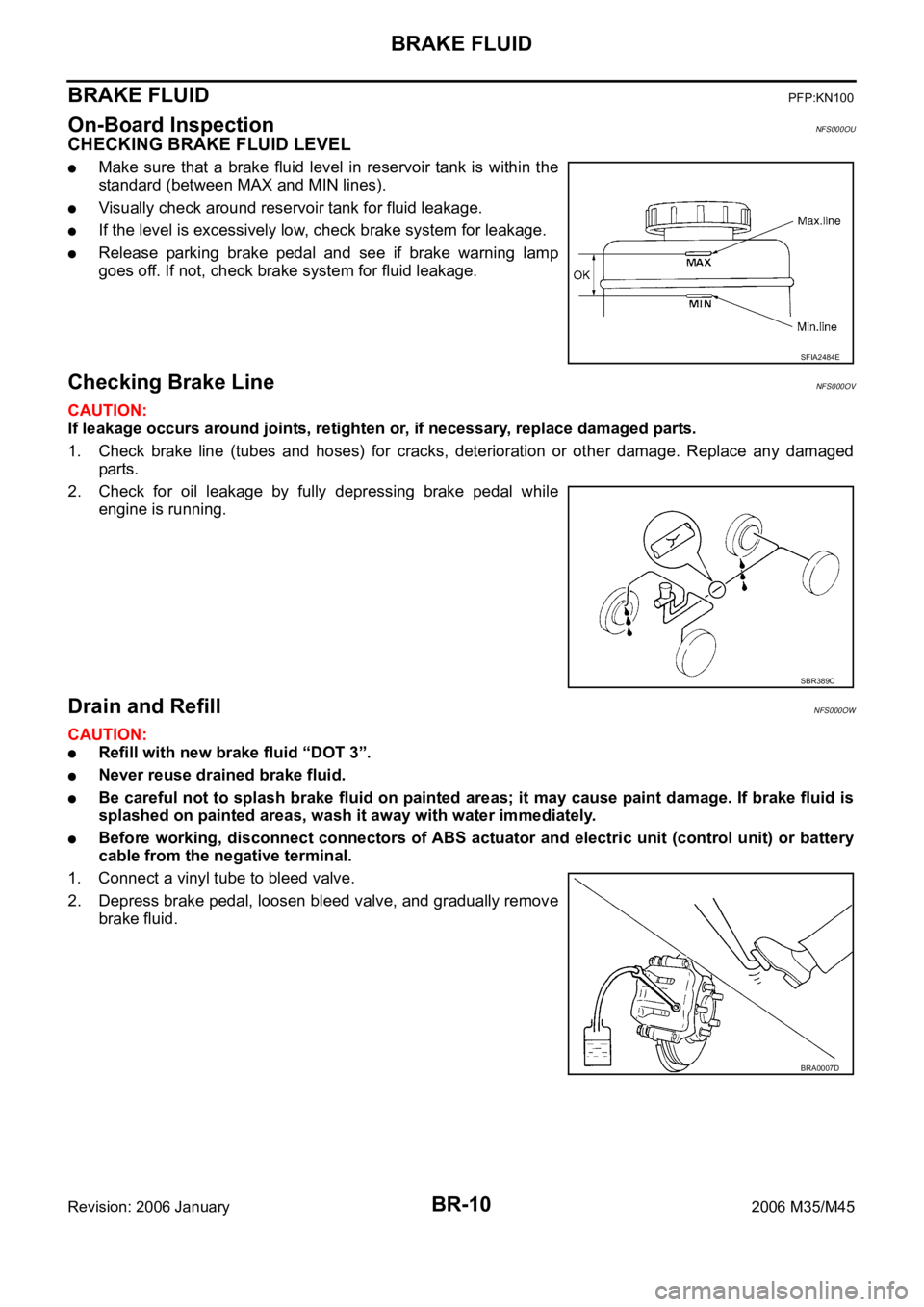
CHECKING BRAKE FLUID LEVEL
Make sure that a brake fluid level in reservoir tank is within the
standard (between MAX and MIN lines).
Visually check around reservoir tank for fluid leakage.
If the level is excessively low, check brake system for leakage.
Release parking brake pedal and see if brake warning lamp
goes off. If not, check brake system for fluid leakage.
Checking Brake LineNFS000OV
CAUTION:
If leakage occurs around joints, retighten or, if necessary, replace damaged parts.
1. Check brake line (tubes and hoses) for cracks, deterioration or other damage. Replace any damaged
parts.
2. Check for oil leakage by fully depressing brake pedal while
engine is running.
Drain and RefillNFS000OW
CAUTION:
Refill with new brake fluid “DOT 3”.
Never reuse drained brake fluid.
Be careful not to splash brake fluid on painted areas; it may cause paint damage. If brake fluid is
splashed on painted areas, wash it away with water immediately.
Before working, disconnect connectors of ABS actuator and electric unit (control unit) or battery
cable from the negative terminal.
1. Connect a vinyl tube to bleed valve.
2. Depress brake pedal, loosen bleed valve, and gradually remove
brake fluid.
SFIA2484E
SBR389C
BRA0007D
Page 1344 of 5621
![INFINITI M35 2006 Factory Service Manual TROUBLE DIAGNOSIS
BRC-33
[VDC/TCS/ABS]
C
D
E
G
H
I
J
K
L
MA
B
BRC
Revision: 2006 January2006 M35/M45
Basic InspectionNFS000QK
BASIC INSPECTION 1: BRAKE FLUID LEVEL, LEAK INSPECTION AND BRAKE PAD
1. C INFINITI M35 2006 Factory Service Manual TROUBLE DIAGNOSIS
BRC-33
[VDC/TCS/ABS]
C
D
E
G
H
I
J
K
L
MA
B
BRC
Revision: 2006 January2006 M35/M45
Basic InspectionNFS000QK
BASIC INSPECTION 1: BRAKE FLUID LEVEL, LEAK INSPECTION AND BRAKE PAD
1. C](/img/42/57023/w960_57023-1343.png)
TROUBLE DIAGNOSIS
BRC-33
[VDC/TCS/ABS]
C
D
E
G
H
I
J
K
L
MA
B
BRC
Revision: 2006 January2006 M35/M45
Basic InspectionNFS000QK
BASIC INSPECTION 1: BRAKE FLUID LEVEL, LEAK INSPECTION AND BRAKE PAD
1. Check fluid level in brake reservoir tank. If fluid level is low, refill brake fluid. Refer to BR-10, "CHECKING
BRAKE FLUID LEVEL" .
2. Check for leakage in brake tubes or hoses and around ABS actuator and electric unit (control unit). If
there is leaking or seeping fluid, check the following items.
If the brake tube connections at ABS actuator and electric unit (control unit) are loose, tighten flare nuts
to the specified torque. Then inspect again and confirm that there is no leakage.
If flare nuts or screws of ABS actuator and electric unit (control unit) are damaged and loose, replace
damaged parts. Then inspect again and confirm that there is no leakage.
If there is leakage at any location other than ABS actuator and electric unit (control unit) connections,
wipe away leakage with clean cloth. Then inspect again and confirm that there is no leakage.
If there is leakage from ABS actuator and electric unit (control unit), wipe away leakage with clean cloth.
Then inspect again. If there is still leakage, replace ABS actuator and electric unit (control unit).
CAUTION:
ABS actuator and electric unit (control unit) cannot be disassembled.
3. Check brake disc rotor and pads. Refer to BR-28, "
DISC ROTOR INSPECTION" (front disc rotor), BR-23,
"PAD WEAR INSPECTION" (front brake pad), BR-34, "DISC ROTOR INSPECTION" (rear disc rotor), BR-
29, "PAD WEAR INSPECTION" (rear brake pad).
BASIC INSPECTION 2: LOOSENESS OF POWER SYSTEM TERMINALS AND BATTERY
Check battery for looseness on battery positive/negative terminals and ground connection. Also make sure
battery voltage does not drop and alternator is normal.
BASIC INSPECTION 3: ABS WARNING LAMP, BRAKE WARNING LAMP, VDC OFF INDICATOR
LAMP AND SLIP INDICATOR LAMP
ON and OFF Timing for Warning Lamp and Indicator Lamp
: ON –: OFF
Note1: Brake warning lamp will turn on in case of parking brake operation (when switch is ON) or of brake fluid level switch operation
(when brake fluid is insufficient).
Note2: After starting engine, brake warning lamp is turned off.
Check the following items when unsuitable for an above condition.
ABS warning lamp: BRC-51, "Inspection 16: CAN Communication Circuit"
Brake warning lamp: BRC-51, "Inspection 16: CAN Communication Circuit" , BRC-48, "Inspection 12:
Brake Fluid Level Switch Circuit" , BRC-52, "Inspection 18: Parking Brake Switch Circuit"
VDC OFF indicator lamp:BRC-51, "Inspection 16: CAN Communication Circuit" , BRC-51, "Inspection 17:
VDC OFF Switch Circuit"
SLIP indicator lamp: BRC-51, "Inspection 16: CAN Communication Circuit"
If malfunction is not found, refer to BRC-53, "Inspection 19: Warning Lamp and Indicator Lamp Circuit" .
Condition ABS warning lampVDC OFF
indicator lampSLIP indicator lampBrake warning lamp
[Note1]
Ignition SW OFF – – – –
For 1 second after turning ON igni-
tion switch
[Note 2]
1 second later after turning ON
ignition switch–––
[Note 2]
VDC OFF switch turned ON. (VDC
function is OFF.)–
––
VDC/TCS function is malfunction-
ing.–
–
ABS function is malfunctioning.
–
EBD function is malfunctioning.
Page 3126 of 5621
![INFINITI M35 2006 Factory Service Manual FRONT TIMING CHAIN CASE
EM-63
[VQ35DE]
C
D
E
F
G
H
I
J
K
L
MA
EM
Revision: 2006 January2006 M35/M45
10. Rotate crankshaft pulley in normal direction (clockwise when viewed from front) to c INFINITI M35 2006 Factory Service Manual FRONT TIMING CHAIN CASE
EM-63
[VQ35DE]
C
D
E
F
G
H
I
J
K
L
MA
EM
Revision: 2006 January2006 M35/M45
10. Rotate crankshaft pulley in normal direction (clockwise when viewed from front) to c](/img/42/57023/w960_57023-3125.png)
FRONT TIMING CHAIN CASE
EM-63
[VQ35DE]
C
D
E
F
G
H
I
J
K
L
MA
EM
Revision: 2006 January2006 M35/M45
10. Rotate crankshaft pulley in normal direction (clockwise when viewed from front) to confirm it turns
smoothly.
11. For the following operations, perform steps in the reverse order of removal.
INSPECTION AFTER INSTALLATION
Inspection for Leaks
The following are procedures for checking fluids leak, lubricates leak.
Before starting engine, check oil/fluid levels including engine coolant and engine oil. If less than required
quantity, fill to the specified level. Refer to MA-12, "
RECOMMENDED FLUIDS AND LUBRICANTS" .
Use procedure below to check for fuel leakage.
–Turn ignition switch “ON” (with engine stopped). With fuel pressure applied to fuel piping, check for fuel
leakage at connection points.
–Start engine. With engine speed increased, check again for fuel leakage at connection points.
Run engine to check for unusual noise and vibration.
NOTE:
If hydraulic pressure inside chain tensioner drops after removal/installation, slack in guide may generate a
pounding noise during and just after the engine start. However, this does not indicate an unusualness.
Noise will stop after hydraulic pressure rises.
Warm up engine thoroughly to make sure there is no leakage of fuel, or any oil/fluids including engine oil
and engine coolant.
Bleed air from lines and hoses of applicable lines, such as in cooling system.
After cooling down engine, again check oil/fluid levels including engine oil and engine coolant. Refill to the
specified level, if necessary.
Summary of the inspection items:
* Transmission/transaxle/CVT fluid, power steering fluid, brake fluid, etc. Item Before starting engine Engine running After engine stopped
Engine coolant Level Leakage Level
Engine oil Level Leakage Level
Other oils and fluid* Level Leakage Level
Fuel Leakage Leakage Leakage