seat adjustment INFINITI M35 2006 Factory Service Manual
[x] Cancel search | Manufacturer: INFINITI, Model Year: 2006, Model line: M35, Model: INFINITI M35 2006Pages: 5621, PDF Size: 65.56 MB
Page 10 of 5621
ACS-1
AUTO CRUISE CONTROL SYSTEM
K ELECTRICAL
CONTENTS
C
D
E
F
G
H
I
J
L
M
SECTION ACS
A
B
ACS
Revision: 2006 January2006 M35/M45
AUTO CRUISE CONTROL SYSTEM
ASCD
AUTOMATIC SPEED CONTROL DEVICE (ASCD) ..... 3
Description ............................................................... 3
ICC
PRECAUTIONS .......................................................... 4
Precautions for Supplemental Restraint System
(SRS) “AIR BAG” and “SEAT BELT PRE-TEN-
SIONER” .................................................................. 4
Precautions for ICC System Service ........................ 4
PREPARATION ........................................................... 5
Special Service Tools ............................................... 5
DESCRIPTION ............................................................ 6
Outline ...................................................................... 6
VEHICLE-TO-VEHICLE DISTANCE CONTROL
MODE ................................................................... 6
CONVENTIONAL (FIXED SPEED) CRUISE
CONTROL MODE ................................................. 6
BRAKE ASSIST (WITH PREVIEW FUNCTION) ..... 6
System Diagram ....................................................... 6
Components Description .......................................... 7
CAN Communication ................................................ 7
CAN COMMUNICATION UNIT ............................. 7
Switch Operation ...................................................... 8
IN VEHICLE-TO-VEHICLE DISTANCE CON-
TROL MODE ......................................................... 8
IN CONVENTIONAL (FIXED SPEED) CRUISE
CONTROL MODE ................................................. 8
ICC System Display ................................................. 9
IN VEHICLE-TO-VEHICLE DISTANCE CON-
TROL MODE ......................................................... 9
IN CONVENTIONAL (FIXED SPEED) CRUISE
CONTROL MODE ................................................. 9
ACTION TEST .......................................................... 10
ICC System Running Test ...................................... 10
VEHICLE-TO-VEHICLE DISTANCE CONTROL
MODE ................................................................. 10
CONVENTIONAL (FIXED SPEED) CRUISE
CONTROL MODE ................................................ 11LASER BEAM AIMING ADJUSTMENT ................... 13
Outline .................................................................... 13
Preparation ............................................................. 13
Outline of Adjustment Procedure ............................ 13
Setting the ICC Target Board .................................. 13
ADJUSTING HEIGHT OF THE TARGET ............ 13
ADJUSTING THE RIGHT-LEFT POSITION OF
THE TARGET ...................................................... 14
SETTING THE TARGET ..................................... 14
Aiming Adjustment .................................................. 16
CHECK AFTER THE ADJUSTMENT .................. 18
ELECTRICAL UNITS LOCATION ............................ 19
Component Parts and Harness Connector Location ... 19
WIRING DIAGRAM ................................................... 20
Schematic ............................................................... 20
Wiring Diagram — ICC — ...................................... 21
TERMINALS AND REFERENCE VALUE ................. 26
Terminals and Reference Value for ICC Sensor Inte-
grated Unit .............................................................. 26
TROUBLE DIAGNOSIS - GENERAL DESCRIP-
TION .......................................................................
... 27
Fail-Safe Function .................................................. 27
Work Flow ............................................................... 27
CONSULT-II Function (ICC) ................................... 28
DESCRIPTION .................................................... 28
CONSULT-II BASIC OPERATION ....................... 28
WORK SUPPORT ............................................... 29
SELF-DIAGNOSTIC RESULTS ........................... 30
DATA MONITOR ................................................. 30
ACTIVE TEST ..................................................... 33
Self-Diagnostic Function ......................................... 34
WITH CONSULT-II .............................................. 34
WITHOUT CONSULT-II ....................................... 34
SELF-DIAGNOSIS BY DOT MATRIX LCD WILL
NOT RUN ............................................................ 36
TROUBLE DIAGNOSIS FOR SELF-DIAGNOSTIC
ITEMS ........................................................................ 39
Diagnostic Trouble Code (DTC) Chart ................... 39
DTC 0 CONTROL UNIT ......................................... 41
DTC 1 POWER SUPPLY CIR, DTC 2 POWER SUP-
Page 622 of 5621
AV-1
AUDIO-VISUAL SYSTEM
K ELECTRICAL
CONTENTS
C
D
E
F
G
H
I
J
L
M
SECTION AV
A
B
AV
Revision: 2006 January2006 M35/M45
AUDIO-VISUAL SYSTEM
WITHOUT MOBILE ENTERTAINMENT SYS-
TEM
PRECAUTION ............................................................ 6
Precautions for Supplemental Restraint System
(SRS) “AIR BAG” and “SEAT BELT PRE-TEN-
SIONER” .................................................................. 6
Precautions for Trouble Diagnosis ........................... 6
AV COMMUNICATION SYSTEM .......................... 6
Precautions for Harness Repair ............................... 6
AV COMMUNICATION SYSTEM .......................... 6
PREPARATION ........................................................... 7
Commercial Service Tools ........................................ 7
SYSTEM DESCRIPTION ............................................ 8
System Functions ..................................................... 8
AUDIO ................................................................... 8
VEHICLE INFORMATION SYSTEM ..................... 8
NAVIGATION SYSTEM ......................................... 8
HANDS-FREE PHONE ....................................... 10
REAR VIEW MONITOR ...................................... 10
Component Description ........................................... 11
AUDIO UNIT ........................................................ 11
BOSE AMP .......................................................... 11
SATELLITE TUNER ............................................ 12
AV CONTROL UNIT (WITHOUT NAVI) .............. 12
NAVI CONTROL UNIT (WITH NAVI) .................. 12
FRONT DISPLAY UNIT ...................................... 13
DVD PLAYER ...................................................... 13
CAMERA CONTROL UNIT ................................. 13
CAN Communication System Description .............. 13
CAN Communication Unit ...................................... 13
Schematic — Base Audio System — ..................... 14
Wiring Diagram — AV — / Base Audio System ..... 15
Schematic — BOSE Audio 2ch System — ............ 26
W i r i n g D i a g r a m — A V — / B O S E A u d i o 2 c h S y s t e m ... 28
Schematic — BOSE Surround Audio 5.1ch System
— ............................................................................ 42Wiring Diagram — AV — / BOSE Surround Audio
5.1ch System .......................................................... 45
Component Parts Location ..................................... 64
Location of Antenna ................................................ 65
TERMINALS AND REFERENCE VALUE FOR CON-
TROL UNIT ............................................................... 66
Audio Unit for Base System .................................... 66
Audio Unit for BOSE System .................................. 68
BOSE Amp ............................................................. 70
Satellite Radio Tuner .............................................. 74
AV (NAVI) Control Unit ........................................... 75
Front Display Unit ................................................... 78
DVD Player ............................................................. 80
Camera Control Unit ............................................ ... 83
DIAGNOSIS SYSTEM ............................................... 86
Multifunction Switch Self-Diagnosis Function ......... 86
SELF-DIAGNOSIS MODE .................................. 86
FINISHING SELF-DIAGNOSIS MODE ............... 86
Multi AV System Diagnosis Functions .................... 86
On Board Diagnosis ............................................... 86
DESCRIPTION .................................................... 86
STARTING PROCEDURE ................................... 87
Self Diagnosis Mode ............................................... 88
DIAGNOSIS RESULT .......................................... 89
Confirmation/Adjustment Mode .............................. 91
DISPLAY DIAGNOSIS ......................................... 91
VEHICLE SIGNALS ............................................ 92
SPEAKER TEST ................................................. 92
CLIMATE CONTROL ........................................... 92
NAVIGATION ....................................................... 93
ERROR HISTORY ............................................... 93
VEHICLE CAN DIAGNOSIS ............................... 97
AV COMM DIAGNOSIS ....................................... 97
HANDSFREE PHONE ........................................ 98
CAMERA CONT. ................................................. 99
BLUETOOTH .....................................................100
DELETE UNIT CONNECTION LOG .................100
Page 623 of 5621

AV-2Revision: 2006 January2006 M35/M45 Rear View Monitor Guiding Line Adjustment ........101
CONSULT-II Functions (Multi AV) .........................102
OPERATION PROCEDURE ..............................102
SELF-DIAG RESULTS ......................................103
DATA MONITOR ................................................105
AV COMM MONITOR ........................................106
ECU PART NUMBER ........................................107
TROUBLE DIAGNOSIS ..........................................108
Multifunction Switch Cannot Be Operated ............108
RGB Image Is Not Displayed ................................108
RGB Screen Is Rolling ..........................................109
Rear View Monitor Image Is Not Displayed ..........109
DVD IMAGE IS DISPLAYED .............................109
DVD IMAGE IS NOT DISPLAYED .....................112
IT CANNOT BE SWITCHED TO REAR VIEW
MONITOR IMAGE .............................................112
DVD Image Is Not Displayed ................................113
Warning Message of Whether Rear View Image Is
Rolling or Not Displayed .......................................115
DVD Operation Screen Is Not Displayed ..............115
It Cannot Be Switched to DVD Mode ...................115
Sound Is Not Output (Voice Guidance and TEL
Voice Are Normal) ................................................116
DVD AND AUDIO SOUND ARE NOT OUTPUT .116
DVD SOUND IS NOT OUTPUT ........................116
Voice Activated Control System Is Not Activated . 116
THE SCREEN IS SWITCHED BY PRESSING
THE STEERING SWITCH .................................116
THE SCREEN IS NOT SWITCHED BY PRESS-
ING THE STEERING SWITCH .........................117
Steering Switch Cannot Be Operated ...................118
NONE OF THE OPERATIONS WORK. .............118
“ENTER”, “MENU UP-DOWN”, AND “SOURCE”
SWITCHES ARE NOT OPERATED ..................118
“PTT/TEL”, “BACK”, AND “VOLUME CONTROL”
SWITCHES ARE NOT OPERATED ..................119
The Hands-Free Phone Cannot Be Used .............119
THE VOICE CANNOT BE HEARD ....................119
THE VOICE CANNOT BE TRANSMITTED .......120
Voice Guidance Is Not Heard (Base System) .......120
Voice Guidance Is Not Heard (BOSE System) .....121
Example of Symptoms Judged Not Malfunction ...122
BASIC OPERATION ..........................................122
VEHICLE ICON .................................................122
MAP DVD-ROM .................................................123
ROUTE CALCULATION AND VISUAL GUID-
ANCE .................................................................123
VOICE GUIDANCE ...........................................124
VOICE RECOGNITION .....................................124
REAR VIEW MONITOR ....................................124
EXAMPLES OF VEHICLE MARK DISPLACE-
MENT ................................................................125
VEHICLE MARK SHOWS A POSITION WHICH
IS COMPLETELY WRONG ...............................128
VEHICLE MARK JUMPS ...................................128
VEHICLE MARK IS IN A RIVER OR SEA .........129
VEHICLE MARK AUTOMATICALLY ROTATES .129
WHEN DRIVING ON SAME ROAD, SOME-
TIMES VEHICLE MARK IS IN RIGHT PLACE AND SOMETIMES IT IS WRONG PLACE ........129
LOCATION CORRECTION BY MAP-MATCH-
ING IS SLOW ....................................................
.129
ALTHOUGH GPS RECEIVING DISPLAY IS
GREEN, VEHICLE MARK DOES NOT RETURN
TO CORRECT LOCATION ................................129
NAME OF CURRENT PLACE IS NOT DIS-
PLAYED .............................................................129
CONTENTS OF DISPLAY DIFFER FOR BIRD-
VIEW® AND THE (FLAT) MAP SCREEN ..........129
REMOVAL AND INSTALLATION ............................130
Removal and Installation/Precautions for Replace-
ment ......................................................................130
REMOVAL OF BATTERY ..................................130
Audio Unit .............................................................130
REMOVAL ..........................................................130
INSTALLATION ..................................................130
Front Door Speaker ............................................. .130
REMOVAL ..........................................................130
INSTALLATION ..................................................130
Rear Door Speaker ...............................................131
REMOVAL ..........................................................131
INSTALLATION ..................................................131
Tweeter .................................................................131
REMOVAL ..........................................................131
INSTALLATION ..................................................131
Center Speaker .....................................................131
REMOVAL ..........................................................131
INSTALLATION ..................................................131
Seat Speaker ........................................................132
REMOVAL ..........................................................132
INSTALLATION ..................................................132
Rear Surround Speaker ........................................132
REMOVAL ..........................................................132
INSTALLATION ..................................................132
Woofer ..................................................................132
REMOVAL ..........................................................132
INSTALLATION ..................................................133
BOSE Amp ............................................................133
REMOVAL ..........................................................133
INSTALLATION ..................................................133
AudioPilot® Microphone .......................................133
REMOVAL ..........................................................133
INSTALLATION ..................................................133
Satellite Radio Tuner .........................................
....133
REMOVAL ..........................................................133
INSTALLATION ..................................................134
Antenna Amp ........................................................134
REMOVAL ..........................................................134
INSTALLATION ..................................................134
Satellite Radio Antenna ........................................134
REMOVAL ..........................................................134
INSTALLATION ..................................................135
Splitter ...................................................................135
REMOVAL ..........................................................135
INSTALLATION ..................................................135
AV (NAVI) Control Unit ......................................... .135
REMOVAL ..........................................................135
INSTALLATION ..................................................136
Page 624 of 5621

AV-3
C
D
E
F
G
H
I
J
L
MA
B
AV
Revision: 2006 January2006 M35/M45 Front Display Unit (Base System) ........................136
REMOVAL ........................................................
.136
INSTALLATION .................................................136
Front Display Unit (BOSE System) ......................137
REMOVAL ........................................................
.137
INSTALLATION .................................................137
Multifunction Switch .............................................137
REMOVAL ........................................................
.137
INSTALLATION .................................................137
Preset Switch .......................................................137
REMOVAL ........................................................
.137
INSTALLATION .................................................138
Steering Switch ....................................................138
REMOVAL ........................................................
.138
INSTALLATION .................................................138
DVD Player ..........................................................138
REMOVAL ........................................................
.138
INSTALLATION .................................................139
Auxiliary Input Jacks ............................................140
REMOVAL ........................................................
.140
INSTALLATION .................................................140
Microphone ..........................................................140
REMOVAL ........................................................
.140
INSTALLATION .................................................140
GPS Antenna .......................................................140
REMOVAL ........................................................
.140
INSTALLATION .................................................141
Camera Control Unit ............................................142
REMOVAL ........................................................
.142
INSTALLATION .................................................142
Rear View Camera ...............................................142
REMOVAL ........................................................
.142
INSTALLATION .................................................142
Steering Angle Sensor .........................................142
REMOVAL ........................................................
.142
INSTALLATION .................................................143
WITH MOBILE ENTERTAINMENT SYSTEM
PRECAUTION ........................................................144
Precautions for Supplemental Restraint System
(SRS) “AIR BAG” and “SEAT BELT PRE-TEN-
SIONER” ..............................................................144
Precautions for Trouble Diagnosis .......................144
AV COMMUNICATION SYSTEM ......................144
Precautions for Harness Repair ...........................144
AV COMMUNICATION SYSTEM ......................144
PREPARATION .......................................................145
Commercial Service Tools ....................................145
SYSTEM DESCRIPTION ........................................146
System Functions .................................................146
AUDIO ...............................................................146
VEHICLE INFORMATION SYSTEM .................146
NAVIGATION SYSTEM .....................................146
MOBILE ENTERTAINMENT SYSTEM ..............148
HANDS-FREE PHONE .....................................148
REAR VIEW MONITOR ....................................148Component Description ........................................149
AUDIO UNIT ..................................................... .149
BOSE AMP ........................................................149
SATELLITE TUNER ..........................................150
AV CONTROL UNIT (WITHOUT NAVI) .............150
NAVI CONTROL UNIT (WITH NAVI) .................150
FRONT DISPLAY UNIT .....................................150
REAR DISPLAY UNIT .......................................151
VIDEO DISTRIBUTOR ......................................151
DVD PLAYER ....................................................151
CAMERA CONTROL UNIT ...............................151
CAN Communication System Description ............152
CAN Communication Unit .....................................152
Schematic — BOSE Audio 2ch System — ...........153
W i r i n g D i a g r a m — A V — / B O S E A u d i o 2 c h S y s t e m .156
Schematic — BOSE Surround Audio 5.1ch System
— ..........................................................................175
Wiring Diagram — AV — / BOSE Surround Audio
5.1ch System ........................................................178
Component Parts Location ...................................202
Location of Antenna ..............................................203
TERMINALS AND REFERENCE VALUE FOR CON-
TROL UNIT .............................................................204
Audio Unit .............................................................204
BOSE Amp ...........................................................206
Satellite Radio Tuner ............................................210
AV (NAVI) Control Unit .........................................211
Video Distributor ...................................................214
Front Display Unit ................................................
.219
Rear Display Unit ..................................................221
DVD Player ...........................................................223
Headphone Amp ...................................................226
Camera Control Unit ............................................ .227
DIAGNOSIS SYSTEM .............................................230
Multifunction Switch Self-Diagnosis Function .......230
SELF-DIAGNOSIS MODE ................................230
FINISHING SELF-DIAGNOSIS MODE .............230
Multi AV System Diagnosis Functions ..................230
On Board Diagnosis .............................................230
DESCRIPTION ..................................................230
STARTING PROCEDURE .................................231
Self Diagnosis .......................................................232
DIAGNOSIS RESULTS .....................................233
Confirmation/Adjustment Mode ............................235
DISPLAY DIAGNOSIS .......................................235
VEHICLE SIGNALS ..........................................236
SPEAKER TEST ...............................................236
CLIMATE CONTROL .........................................236
NAVIGATION .....................................................237
ERROR HISTORY .............................................237
VEHICLE CAN DIAGNOSIS .............................241
AV COMM DIAGNOSIS .....................................241
HANDSFREE PHONE ......................................242
REAR DISPLAY .................................................242
CAMERA CONT. ...............................................243
BLUETOOTH .....................................................244
DELETE UNIT CONNECTION LOG .................244
Page 625 of 5621

AV-4Revision: 2006 January2006 M35/M45 Rear View Monitor Guiding Line Adjustment ........245
CONSULT-II Functions (Multi AV) .........................246
OPERATION PROCEDURE ..............................246
SELF-DIAG RESULTS ......................................247
DATA MONITOR ................................................250
AV COMM MONITOR ........................................251
ECU PART NUMBER ........................................252
TROUBLE DIAGNOSIS ..........................................253
Multifunction Switch Cannot Be Operated ............253
RGB Image Is Not Displayed ................................253
RGB IMAGE IS NOT DISPLAYED ON FRONT
AND REAR DISPLAYS ......................................253
ONLY FRONT DISPLAY ....................................253
ONLY REAR DISPLAY ......................................254
RGB Screen Is Rolling. .........................................255
ONLY FRONT DISPLAY ....................................255
ONLY REAR DISPLAY ......................................257
Rear View Monitor Image Is Not Displayed ..........259
DVD IMAGE IS DISPLAYED .............................259
DVD IMAGE IS NOT DISPLAYED .....................261
IT CANNOT BE SWITCHED TO REAR VIEW
MONITOR IMAGE .............................................262
DVD Image Is Not Displayed ................................263
ONLY FRONT DISPLAY ....................................263
ONLY REAR DISPLAY ......................................265
BOTH FRONT DISPLAY AND REAR DISPLAY .266
Warning Message of Whether Rear View Image Is
Rolling or Not Displayed .......................................267
DVD Operation Screen Is Not Displayed ..............269
ONLY FRONT DISPLAY ....................................269
ONLY REAR DISPLAY ......................................269
It Cannot Be Switched to DVD Mode ...................270
Sound Is Not Output (Voice Guidance and TEL
Voice Are Normal) ................................................270
DVD AND AUDIO SOUND ARE NOT OUTPUT .270
DVD SOUND IS NOT OUTPUT ........................270
HEADPHONE SOUND IS NOT OUTPUT (BOTH
SIDES) ...............................................................271
Voice Activated Control System Is Not Activated . 272
THE SCREEN IS SWITCHED BY PRESSING
THE STEERING SWITCH .................................272
THE SCREEN IS NOT SWITCHED BY PRESS-
ING THE STEERING SWITCH .........................273
Steering Switch Cannot Be Operated ...................273
NONE OF THE OPERATIONS WORK. .............273
“ENTER”, “MENU UP-DOWN”, AND “SOURCE”
SWITCHES ARE NOT OPERATED ..................273
“PTT/TEL”, “BACK”, AND “VOLUME CONTROL”
SWITCHES ARE NOT OPERATED ..................274
The Hands-Free Phone Cannot Be Used .............275
THE VOICE CANNOT BE HEARD ....................275
THE VOICE CANNOT BE TRANSMITTED .......275
Voice Guidance Is Not Heard ...............................276
Example of Symptoms Judged Not Malfunction ...277
BASIC OPERATION ..........................................277
VEHICLE ICON .................................................277
MAP DVD-ROM .................................................278
ROUTE CALCULATION AND VISUAL GUID-
ANCE .................................................................278
VOICE GUIDANCE ............................................279
VOICE RECOGNITION .....................................279
REAR VIEW MONITOR .....................................279
REMOTE CONTROLLER ..................................280
EXAMPLES OF VEHICLE MARK DISPLACE-
MENT .................................................................280
VEHICLE MARK SHOWS A POSITION WHICH
IS COMPLETELY WRONG ...............................283
VEHICLE MARK JUMPS ...................................283
VEHICLE MARK IS IN A RIVER OR SEA .........284
VEHICLE MARK AUTOMATICALLY ROTATES .284
WHEN DRIVING ON SAME ROAD, SOME-
TIMES VEHICLE MARK IS IN RIGHT PLACE
AND SOMETIMES IT IS WRONG PLACE ........284
LOCATION CORRECTION BY MAP-MATCH-
ING IS SLOW ....................................................
.284
ALTHOUGH GPS RECEIVING DISPLAY IS
GREEN, VEHICLE MARK DOES NOT RETURN
TO CORRECT LOCATION ................................284
NAME OF CURRENT PLACE IS NOT DIS-
PLAYED .............................................................284
CONTENTS OF DISPLAY DIFFER FOR BIRD-
VIEW® AND THE (FLAT) MAP SCREEN ..........284
REMOVAL AND INSTALLATION ............................285
Removal and Installation/Precautions for Replace-
ment ......................................................................285
REMOVAL OF BATTERY ..................................285
Audio Unit .............................................................285
REMOVAL ..........................................................285
INSTALLATION ..................................................285
Front Door Speaker ............................................. .285
REMOVAL ..........................................................285
INSTALLATION ..................................................285
Rear Door Speaker ...............................................286
REMOVAL ..........................................................286
INSTALLATION ..................................................286
Tweeter .................................................................286
REMOVAL ..........................................................286
INSTALLATION ..................................................286
Center Speaker .....................................................286
REMOVAL ..........................................................286
INSTALLATION ..................................................286
Seat Speaker ........................................................287
REMOVAL ..........................................................287
INSTALLATION ..................................................287
Rear Surround Speaker ........................................287
REMOVAL ..........................................................287
INSTALLATION ..................................................287
Woofer ..................................................................287
REMOVAL .......................................................
...287
INSTALLATION ..................................................288
BOSE Amp ............................................................288
REMOVAL ..........................................................288
INSTALLATION ..................................................288
AudioPilot® Microphone .......................................288
REMOVAL ..........................................................288
INSTALLATION ..................................................288
Satellite Radio Tuner .............................................288
Page 863 of 5621
![INFINITI M35 2006 Factory Service Manual AV-242
[WITH MOBILE ENTERTAINMENT SYSTEM]
DIAGNOSIS SYSTEM
Revision: 2006 January2006 M35/M45
ITM: AV (NAVI) control unit
NOTE:
??? indicates “UNKWN”.
HANDSFREE PHONE
Handsfree Volume Adjustment
T INFINITI M35 2006 Factory Service Manual AV-242
[WITH MOBILE ENTERTAINMENT SYSTEM]
DIAGNOSIS SYSTEM
Revision: 2006 January2006 M35/M45
ITM: AV (NAVI) control unit
NOTE:
??? indicates “UNKWN”.
HANDSFREE PHONE
Handsfree Volume Adjustment
T](/img/42/57023/w960_57023-862.png)
AV-242
[WITH MOBILE ENTERTAINMENT SYSTEM]
DIAGNOSIS SYSTEM
Revision: 2006 January2006 M35/M45
ITM: AV (NAVI) control unit
NOTE:
??? indicates “UNKWN”.
HANDSFREE PHONE
Handsfree Volume Adjustment
The received volume adjustment of hands-free phone can be
adjusted to Low, Medium, and High settings.
Voice Microphone Test
When this function is turned ON, the voice that is input to microphone is output to front speaker via TEL voice
signal line. The microphone and TEL voice signal line can be checked.
Delete Handsfree Memory
Erase the memory related to the hands-free phone.
REAR DISPLAY
Tilt angle (90 to 135 degrees, 105 to 135 degrees) of rear seat
display can be set.
The automatic retraction of rear seat display can be set.
C Rx (RrSeatSW-ITM) OK /??? 0 - 40
C Rx (Audio-ITM) OK /??? 0 - 40
C Rx (Amp-ITM) OK /??? 0 - 40
C Rx (RearCamera-ITM) OK /??? 0 - 40
C Rx (DVD-ITM) OK /??? 0 - 40
C Rx (Video DIST-ITM) OK /??? 0 - 40
C Rx (Remote Cont-ITM) OK /??? 0 - 40
C Rx (Amp-Audio) OK /??? 0 - 40
C Rx (DVD-Audio) OK /??? 0 - 40ItemsStatus
(Current)Counter
(Past)
SKIB3668E
SKIB3693E
Page 940 of 5621
BL-1
BODY, LOCK & SECURITY SYSTEM
I BODY
CONTENTS
C
D
E
F
G
H
J
K
L
M
SECTION BL
A
B
BL
Revision: 2006 January2006 M35/M45
BODY, LOCK & SECURITY SYSTEM
PRECAUTIONS .......................................................... 6
Precautions for Supplemental Restraint System
(SRS) “AIR BAG” and “SEAT BELT PRE-TEN-
SIONER” .................................................................. 6
Precautions for Procedures without Cowl Top Cover ..... 6
Precautions Necessary for Steering Wheel Rotation
after Battery Disconnect ........................................... 6
OPERATION PROCEDURE ................................. 6
Precautions for Work ...........................................
..... 7
PREPARATION ........................................................... 8
Special Service Tools ............................................... 8
Commercial Service Tools ........................................ 8
SQUEAK AND RATTLE TROUBLE DIAGNOSIS ...... 9
Work Flow ................................................................ 9
CUSTOMER INTERVIEW ..................................... 9
DUPLICATE THE NOISE AND TEST DRIVE ..... 10
CHECK RELATED SERVICE BULLETINS ......... 10
LOCATE THE NOISE AND IDENTIFY THE
ROOT CAUSE .................................................... 10
REPAIR THE CAUSE ......................................... 10
CONFIRM THE REPAIR ...................................... 11
Generic Squeak and Rattle Troubleshooting .......... 11
INSTRUMENT PANEL ......................................... 11
CENTER CONSOLE ............................................ 11
DOORS ................................................................ 11
TRUNK ................................................................ 12
SUNROOF/HEADLINING ................................... 12
SEATS ................................................................. 12
UNDERHOOD ..................................................... 12
Diagnostic Worksheet ............................................ 13
HOOD ....................................................................... 15
Fitting Adjustment .................................................. 15
Removal and Installation of Hood Assembly .......... 17
REMOVAL ........................................................
... 17
INSTALLETION ................................................... 18
Removal and Installation of Hood Lock Control ..... 18
REMOVAL ........................................................
... 18
INSTALLATION ................................................... 19
Hood Lock Control Inspection ................................ 20RADIATOR CORE SUPPORT .................................. 21
Removal and Installation ........................................ 21
REMOVAL ........................................................
... 21
INSTALLATION ................................................... 22
FRONT FENDER ................................................... ... 23
Removal and Installation ........................................ 23
REMOVAL ........................................................
... 23
INSTALLATION ................................................... 23
POWER DOOR LOCK SYSTEM .............................. 24
Component Parts and Harness Connector Location ... 24
System Description ................................................. 25
DOOR LOCK ACTUATOR OPERATION ............. 26
FUEL LID OPERATION ....................................... 26
OUTLINE ............................................................. 26
CAN Communication System Description .............. 26
CAN Communication Unit ....................................... 26
Schematic ............................................................... 27
Wiring Diagram —D/LOCK— ................................. 28
Terminals and Reference Value of BCM ................. 31
Work Flow ............................................................... 31
CONSULT-II Function (BCM) ................................. 32
CONSULT-II INSPECTION PROCEDURE .......... 32
CONSULT-II APPLICATION ITEMS .................... 33
Trouble Diagnosis Chart by Symptom .................... 34
Power Supply and Ground Circuit Check of BCM ... 35
Check Door Lock and Unlock Switch ..................... 36
Check Door Lock Actuator/Driver Side ................... 38
Check Door Lock Actuator/Passenger Side ........... 39
Check Door Lock Actuator/Rear LH ....................... 40
Check Door Lock Actuator/Rear RH ....................... 40
Check Fuel Lid Opener Actuator ............................ 41
Door Key Cylinder Switch Check ............................ 42
INTELLIGENT KEY SYSTEM ................................... 44
Component Parts and Harness Connector Location ... 44
System Description ................................................. 48
DOOR LOCK/UNLOCK/TRUNK OPEN FUNC-
TION .................................................................... 48
REMOTE KEYLESS ENTRY FUNCTIONS ......... 52
ENGINE START FUNCTION ............................... 54
WARNING FUNCTION ........................................ 55
Page 951 of 5621

BL-12
SQUEAK AND RATTLE TROUBLE DIAGNOSIS
Revision: 2006 January2006 M35/M45
TRUNK
Trunk noises are often caused by a loose jack or loose items put into the trunk by the owner.
In addition look for:
1. Trunk lid dumpers out of adjustment
2. Trunk lid striker out of adjustment
3. The trunk lid torsion bars knocking together
4. A loose license plate or bracket
Most of these incidents can be repaired by adjusting, securing or insulating the item(s) or component(s) caus-
ing the noise.
SUNROOF/HEADLINING
Noises in the sunroof/headlining area can often be traced to one of the following:
1. Sunroof lid, rail, linkage or seals making a rattle or light knocking noise
2. Sunvisor shaft shaking in the holder
3. Front or rear windshield touching headlining and squeaking
Again, pressing on the components to stop the noise while duplicating the conditions can isolate most of these
incidents. Repairs usually consist of insulating with felt cloth tape.
SEATS
When isolating seat noise it's important to note the position the seat is in and the load placed on the seat when
the noise is present. These conditions should be duplicated when verifying and isolating the cause of the
noise.
Cause of seat noise include:
1. Headrest rods and holder
2. A squeak between the seat pad cushion and frame
3. The rear seatback lock and bracket
These noises can be isolated by moving or pressing on the suspected components while duplicating the con-
ditions under which the noise occurs. Most of these incidents can be repaired by repositioning the component
or applying urethane tape to the contact area.
UNDERHOOD
Some interior noise may be caused by components under the hood or on the engine wall. The noise is then
transmitted into the passenger compartment.
Causes of transmitted underhood noise include:
1. Any component mounted to the engine wall
2. Components that pass through the engine wall
3. Engine wall mounts and connectors
4. Loose radiator mounting pins
5. Hood bumpers out of adjustment
6. Hood striker out of adjustment
These noises can be difficult to isolate since they cannot be reached from the interior of the vehicle. The best
method is to secure, move or insulate one component at a time and test drive the vehicle. Also, engine RPM
or load can be changed to isolate the noise. Repairs can usually be made by moving, adjusting, securing, or
insulating the component causing the noise.
Page 1276 of 5621
BR-1
BRAKE SYSTEM
F BRAKES
CONTENTS
C
D
E
G
H
I
J
K
L
M
SECTION BR
A
B
BR
Revision: 2006 January2006 M35/M45
BRAKE SYSTEM
PRECAUTIONS .......................................................... 3
Precautions for Supplemental Restraint System
(SRS) “AIR BAG” and “SEAT BELT PRE-TEN-
SIONER” .................................................................. 3
Precautions for Procedures without Cowl Top Cover ..... 3
Precautions for Brake System .................................. 3
PREPARATION ........................................................... 4
Commercial Service Tools ........................................ 4
NOISE, VIBRATION AND HARSHNESS (NVH)
TROUBLESHOOTING ................................................ 5
NVH Troubleshooting Chart ..................................... 5
BRAKE PEDAL .......................................................... 6
Inspection and Adjustment ....................................... 6
ADJUSTMENT ...................................................... 7
Removal and Installation .......................................... 7
COMPONENTS .................................................... 7
REMOVAL ........................................................
..... 8
INSPECTION AFTER REMOVAL ......................... 8
INSTALLATION ..................................................... 9
BRAKE FLUID .......................................................... 10
On-Board Inspection .............................................. 10
CHECKING BRAKE FLUID LEVEL .................... 10
Checking Brake Line .............................................. 10
Drain and Refill ....................................................... 10
Bleeding Brake System ........................................... 11
BRAKE TUBE AND HOSE ....................................... 12
Hydraulic Circuit ..................................................... 12
Removal and Installation of Front Brake Tube and
Brake Hose ............................................................ 13
REMOVAL ........................................................
... 13
INSTALLATION ................................................... 13
Removal and Installation of Rear Brake Tube and
Brake Hose ............................................................ 13
REMOVAL ........................................................
... 13
INSTALLATION ................................................... 14
Inspection after Installation .................................... 14
BRAKE MASTER CYLINDER .................................. 15
On-Board Inspection .............................................. 15
LEAK INSPECTION ............................................ 15
Removal and Installation ........................................ 15REMOVAL ........................................................
... 15
INSTALLATION ................................................... 15
Disassembly and Assembly .................................... 16
COMPONENTS ................................................... 16
Disassembly and Assembly .................................... 16
DISASSEMBLY ................................................... 16
ASSEMBLY ......................................................... 17
BRAKE BOOSTER ................................................... 18
On-Board Inspection and Service ........................... 18
OPERATION CHECK .......................................... 18
AIR TIGHT CHECK ............................................. 18
Removal and Installation ........................................ 19
COMPONENTS ................................................... 19
REMOVAL ........................................................
... 19
INSTALLATION ................................................... 19
VACUUM LINES ....................................................... 21
Components ........................................................... 21
Removal and Installation ........................................ 22
Inspection ............................................................... 22
VISUAL INSPECTION ......................................... 22
CHECK VALVE INSPECTION ............................. 22
FRONT DISC BRAKE ............................................... 23
On-Board Inspection ............................................
... 23
PAD WEAR INSPECTION ................................... 23
Components ........................................................... 23
Removal and Installation of Brake Pad .................. 24
REMOVAL ........................................................
... 24
INSTALLATION ................................................... 24
Removal and Installation of Brake Caliper Assembly
... 25
REMOVAL ........................................................
... 25
INSTALLATION ................................................... 25
Disassembly and Assembly of Brake Caliper
Assembly ................................................................ 26
DISASSEMBLY ................................................... 26
INSPECTION AFTER DISASSEMBLY ................ 26
ASSEMBLY ......................................................... 27
DISC ROTOR INSPECTION ............................... 28
BRAKE BURNISHING PROCEDURE ................. 28
REAR DISC BRAKE ................................................. 29
Page 1282 of 5621
BRAKE PEDAL
BR-7
C
D
E
G
H
I
J
K
L
MA
B
BR
Revision: 2006 January2006 M35/M45
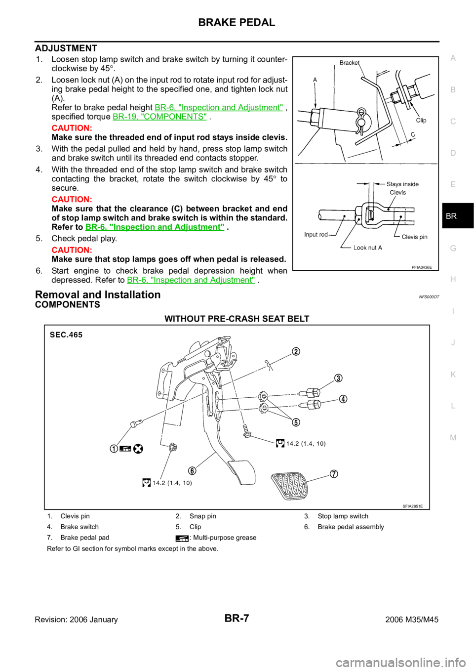
ADJUSTMENT
1. Loosen stop lamp switch and brake switch by turning it counter-
clockwise by 45
.
2. Loosen lock nut (A) on the input rod to rotate input rod for adjust-
ing brake pedal height to the specified one, and tighten lock nut
(A).
Refer to brake pedal height BR-6, "
Inspection and Adjustment" ,
specified torque BR-19, "
COMPONENTS" .
CAUTION:
Make sure the threaded end of input rod stays inside clevis.
3. With the pedal pulled and held by hand, press stop lamp switch
and brake switch until its threaded end contacts stopper.
4. With the threaded end of the stop lamp switch and brake switch
contacting the bracket, rotate the switch clockwise by 45
to
secure.
CAUTION:
Make sure that the clearance (C) between bracket and end
of stop lamp switch and brake switch is within the standard.
Refer to BR-6, "
Inspection and Adjustment" .
5. Check pedal play.
CAUTION:
Make sure that stop lamps goes off when pedal is released.
6. Start engine to check brake pedal depression height when
depressed. Refer to BR-6, "
Inspection and Adjustment" .
Removal and InstallationNFS000OT
COMPONENTS
WITHOUT PRE-CRASH SEAT BELT
PFIA0436E
SFIA2951E
1. Clevis pin 2. Snap pin 3. Stop lamp switch
4. Brake switch 5. Clip 6. Brake pedal assembly
7. Brake pedal pad : Multi-purpose grease
Refer to GI section for symbol marks except in the above.