INSTALLATION INFINITI QX4 2001 Factory Service Manual
[x] Cancel search | Manufacturer: INFINITI, Model Year: 2001, Model line: QX4, Model: INFINITI QX4 2001Pages: 2395, PDF Size: 43.2 MB
Page 8 of 2395
19. A/T Does Not Shift: 22-> 11, When Selector
Lever²2²->²1²Position .........................................255
20. Vehicle Does Not Decelerate By Engine
Brake........................................................................256
21. TCM Self-diagnosis Does Not Activate (PNP,
Overdrive Control and Throttle Position Switches
Circuit Checks) ........................................................257
A/T SHIFT LOCK SYSTEM.........................................265
Description ...............................................................265
Wiring Diagram - SHIFT -........................................266
Diagnostic Procedure ..............................................267
KEY INTERLOCK CABLE..........................................271
Components.............................................................271
Removal ...................................................................271
Installation ................................................................272
ON-VEHICLE SERVICE..............................................273
Control Valve Assembly and Accumulators .............273
Revolution Sensor Replacement .............................274
Turbine Revolution Sensor Replacement................274
Rear Oil Seal Replacement .....................................274
Rear Oil Seal and Companion Flange Oil Seal
Replacement ............................................................275
Parking Components Inspection..............................275
Park/Neutral Position Switch Adjustment ................276
Manual Control Linkage Adjustment........................276
REMOVAL AND INSTALLATION...............................277
Removal ...................................................................277
Installation ................................................................278
OVERHAUL.................................................................281
Components.............................................................281
Oil Channel ..............................................................284
Locations of Needle Bearings, Thrust Washers
and Snap Rings .......................................................285
DISASSEMBLY............................................................286
REPAIR FOR COMPONENT PARTS.........................297Oil Pump ..................................................................297
Control Valve Assembly ...........................................301
Control Valve Upper Body .......................................307
Control Valve Lower Body .......................................312
Reverse Clutch ........................................................314
High Clutch ..............................................................317
Forward and Overrun Clutches ...............................320
Low & Reverse Brake..............................................324
Forward Clutch Drum Assembly ..............................328
Rear Internal Gear and Forward Clutch Hub ..........330
Band Servo Piston Assembly ..................................333
Parking Pawl Components ......................................337
ASSEMBLY..................................................................339
Assembly (1) ............................................................339
Adjustment ...............................................................347
Assembly (2) ............................................................349
SERVICE DATA AND SPECIFICATIONS (SDS).......356
General Specifications .............................................356
Shift Schedule..........................................................356
Stall Revolution ........................................................356
Line Pressure...........................................................356
Return Springs .........................................................357
Accumulator O-ring ..................................................358
Clutches and Brakes ...............................................358
Oil Pump and Low One-way Clutch ........................360
Total End Play..........................................................360
Reverse Clutch Drum End Play ..............................361
Removal and Installation .........................................361
Shift Solenoid Valves ...............................................361
Solenoid Valves .......................................................361
A/T Fluid Temperature Sensor.................................361
Turbine Revolution Sensor ......................................361
Revolution Sensor ...................................................362
Dropping Resistor ....................................................362GI
MA
EM
LC
EC
FE
TF
PD
AX
SU
BR
ST
RS
BT
HA
SC
EL
IDX
CONTENTS(Cont'd)
AT-3
Page 11 of 2395
Precautions for Supplemental Restraint System
(SRS) ªAIR BAGº and ªSEAT BELT
PRE-TENSIONERº
NBAT0001The supplemental Restraint System such as ªAIR BAGº and ªSEAT BELT PRE-TENSIONERº used along with
a seat belt, helps to reduce the risk or severity of injury to the driver and front passenger for certain types of
collision. The SRS system composition which is available to INFINITI QX4 is as follows:
IFor a frontal collision
The Supplemental Restraint System consists of driver air bag module (located in the center of the steer-
ing wheel), front passenger air bag module (located on the instrument panel on passenger side), seat belt
pre-tensioners, a diagnosis sensor unit, warning lamp, wiring harness and spiral cable.
IFor a side collision
The Supplemental Restraint System consists of front side air bag module (located in the outer side of front
seat), satellite sensor, diagnosis sensor unit (one of components of air bags for a frontal collision), wiring
harness, warning lamp (one of components of air bags for a frontal collision).
Information necessary to service the system safely is included in theRS sectionof this Service Manual.
WARNING:
ITo avoid rendering the SRS inoperative, which could increase the risk of personal injury or death
in the event of a collision which would result in air bag inflation, all maintenance must be performed
by an authorized INFINITI dealer.
IImproper maintenance, including incorrect removal and installation of the SRS, can lead to per-
sonal injury caused by unintentional activation of the system. For removal of Spiral Cable and Air
Bag Module, see the RS section.
IDo not use electrical test equipment on any circuit related to the SRS unless instructed to in this
Service Manual. Spiral cable and wiring harnesses covered with yellow insulation tape either just
before the harness connectors or for the complete harness are related to the SRS.
Precautions for On Board Diagnostic (OBD)
System of A/T and Engine
NBAT0002The ECM has an on board diagnostic system. It will light up the malfunction indicator lamp (MIL) to warn the
driver of a malfunction causing emission deterioration.
CAUTION:
IBe sure to turn the ignition switch ªOFFº and disconnect the negative battery terminal before any
repair or inspection work. The open/short circuit of related switches, sensors, solenoid valves, etc.
will cause the MIL to light up.
IBe sure to connect and lock the connectors securely after work. A loose (unlocked) connector will
cause the MIL to light up due to an open circuit. (Be sure the connector is free from water, grease,
dirt, bent terminals, etc.)
IBe sure to route and secure the harnesses properly after work. Interference of the harness with a
bracket, etc. may cause the MIL to light up due to a short circuit.
IBe sure to connect rubber tubes properly after work. A misconnected or disconnected rubber tube
may cause the MIL to light up due to a malfunction of the EGR system or fuel injection system,
etc.
IBe sure to erase the unnecessary malfunction information (repairs completed) from the TCM and
ECM before returning the vehicle to the customer.
SEF289H
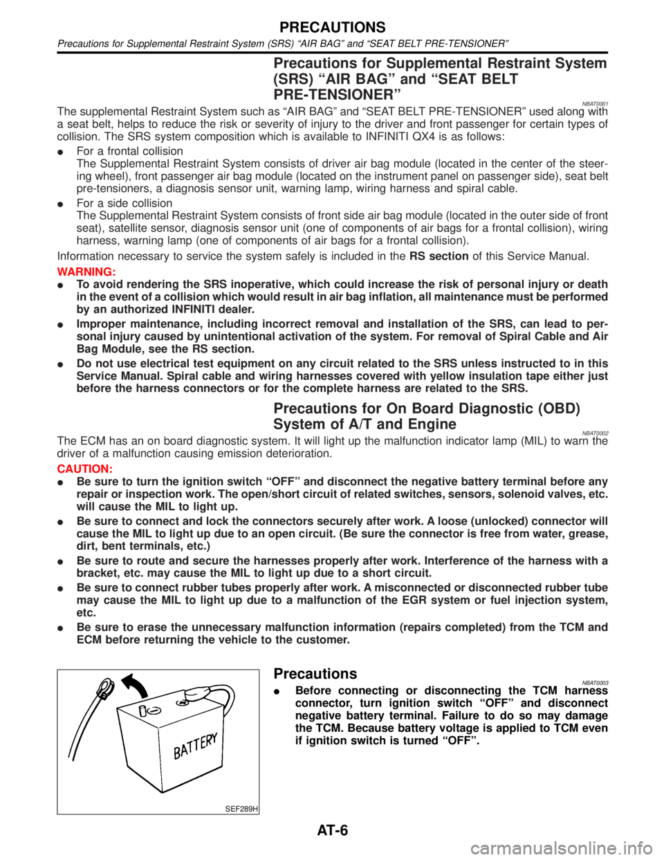
PrecautionsNBAT0003IBefore connecting or disconnecting the TCM harness
connector, turn ignition switch ªOFFº and disconnect
negative battery terminal. Failure to do so may damage
the TCM. Because battery voltage is applied to TCM even
if ignition switch is turned ªOFFº.
PRECAUTIONS
Precautions for Supplemental Restraint System (SRS) ªAIR BAGº and ªSEAT BELT PRE-TENSIONERº
AT-6
Page 14 of 2395
IThe threads in one or more of the converter bolt holes are damaged.
ITransmission failure did not display evidence of damaged or worn internal parts, steel particles or clutch
plate lining material in unit and inside the fluid filter.
IVehicle has been exposed to high mileage (only). The exception may be where the torque converter clutch
dampener plate lining has seen excess wear by vehicles operated in heavy and/or constant traffic, such
as taxi, delivery or police use.
ATF COOLER SERVICENBAT0004S02Replace ATF cooler if excessive foreign material is found in oil pan or clogging strainer.
Replace radiator lower tank (which includes ATF cooler) with a new one and flush cooler line using cleaning
solvent and compressed air. Refer to LC-19, ªREMOVAL AND INSTALLATIONº.
OBD-II SELF-DIAGNOSISNBAT0004S03IA/T self-diagnosis is performed by the TCM in combination with the ECM. The results can be read through
the blinking pattern of the O/D OFF indicator or the malfunction indicator lamp (MIL). Refer to the table on
AT-38 for the indicator used to display each self-diagnostic result.
IThe self-diagnostic results indicated by the MIL are automatically stored in both the ECM and TCM
memories.
Always perform the procedure ªHOW TO ERASE DTCº on AT-35 to complete the repair and avoid
unnecessary blinking of the MIL.
IThe following self-diagnostic items can be detected using ECM self-diagnostic results mode* only when
the O/D OFF indicator lamp does not indicate any malfunctions.
þ PNP switch
þ A/T 1st, 2nd, 3rd, or 4th gear function
þ A/T TCC S/V function (lock-up)
*: For details of OBD-II, refer to EC-59, ªIntroductionº.
ICertain systems and components, especially those related to OBD, may use the new style slide-
locking type harness connector. For description and how to disconnect, refer to EL-5, ªDescrip-
tionº.
Wiring Diagrams and Trouble DiagnosisNBAT0005When you read wiring diagrams, refer to the following:
IGI-11, ªHOW TO READ WIRING DIAGRAMSº.
IEL-9, ªPOWER SUPPLY ROUTINGº for power distribution circuit.
When you perform trouble diagnosis, refer to the following:
IGI-35, ªHOW TO FOLLOW TEST GROUP IN TROUBLE DIAGNOSISº.
IGI-24, ªHOW TO PERFORM EFFICIENT DIAGNOSIS FOR AN ELECTRICAL INCIDENTº.
GI
MA
EM
LC
EC
FE
TF
PD
AX
SU
BR
ST
RS
BT
HA
SC
EL
IDX
PRECAUTIONS
Service Notice or Precautions (Cont'd)
AT-9
Page 277 of 2395
SAT354I
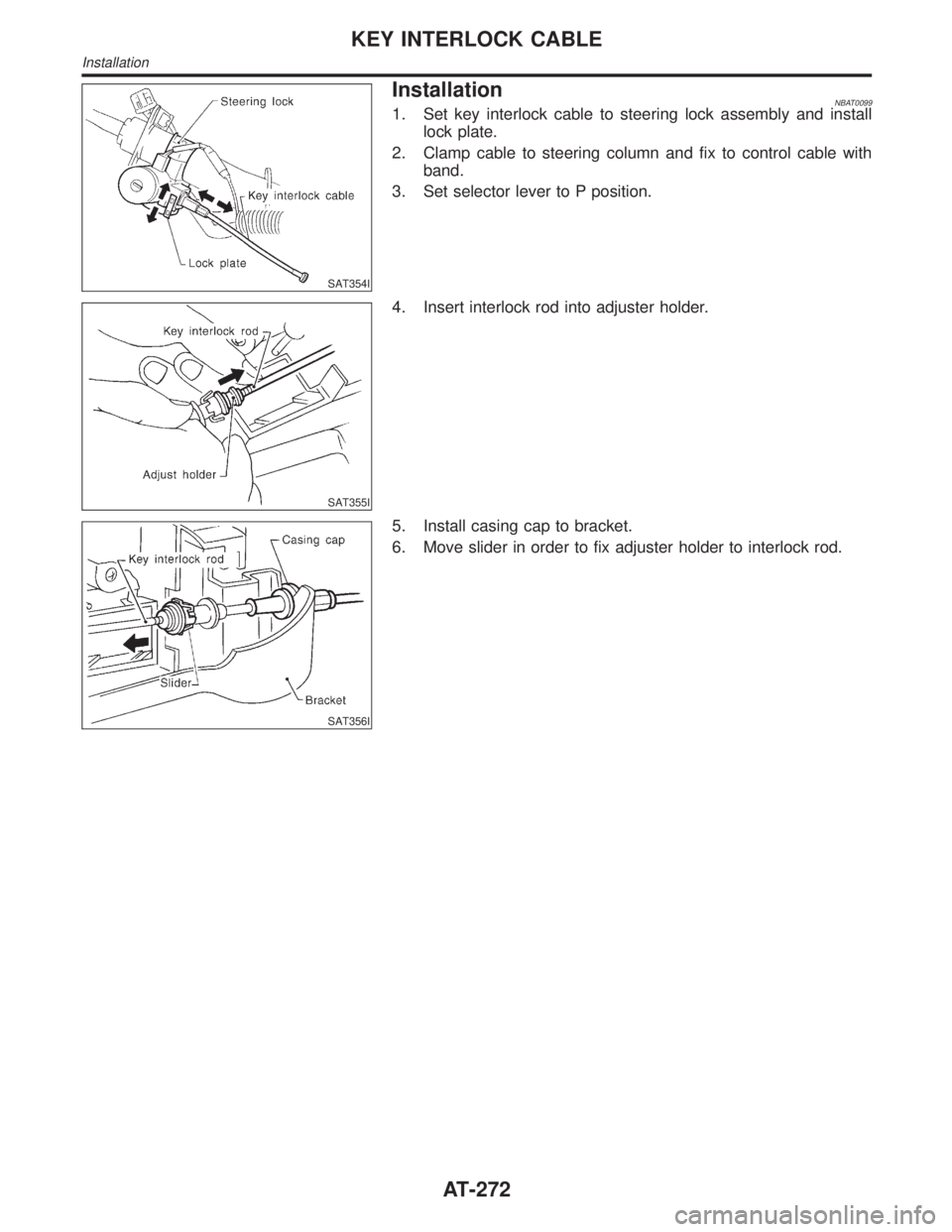
InstallationNBAT00991. Set key interlock cable to steering lock assembly and install
lock plate.
2. Clamp cable to steering column and fix to control cable with
band.
3. Set selector lever to P position.
SAT355I
4. Insert interlock rod into adjuster holder.
SAT356I
5. Install casing cap to bracket.
6. Move slider in order to fix adjuster holder to interlock rod.
KEY INTERLOCK CABLE
Installation
AT-272
Page 282 of 2395
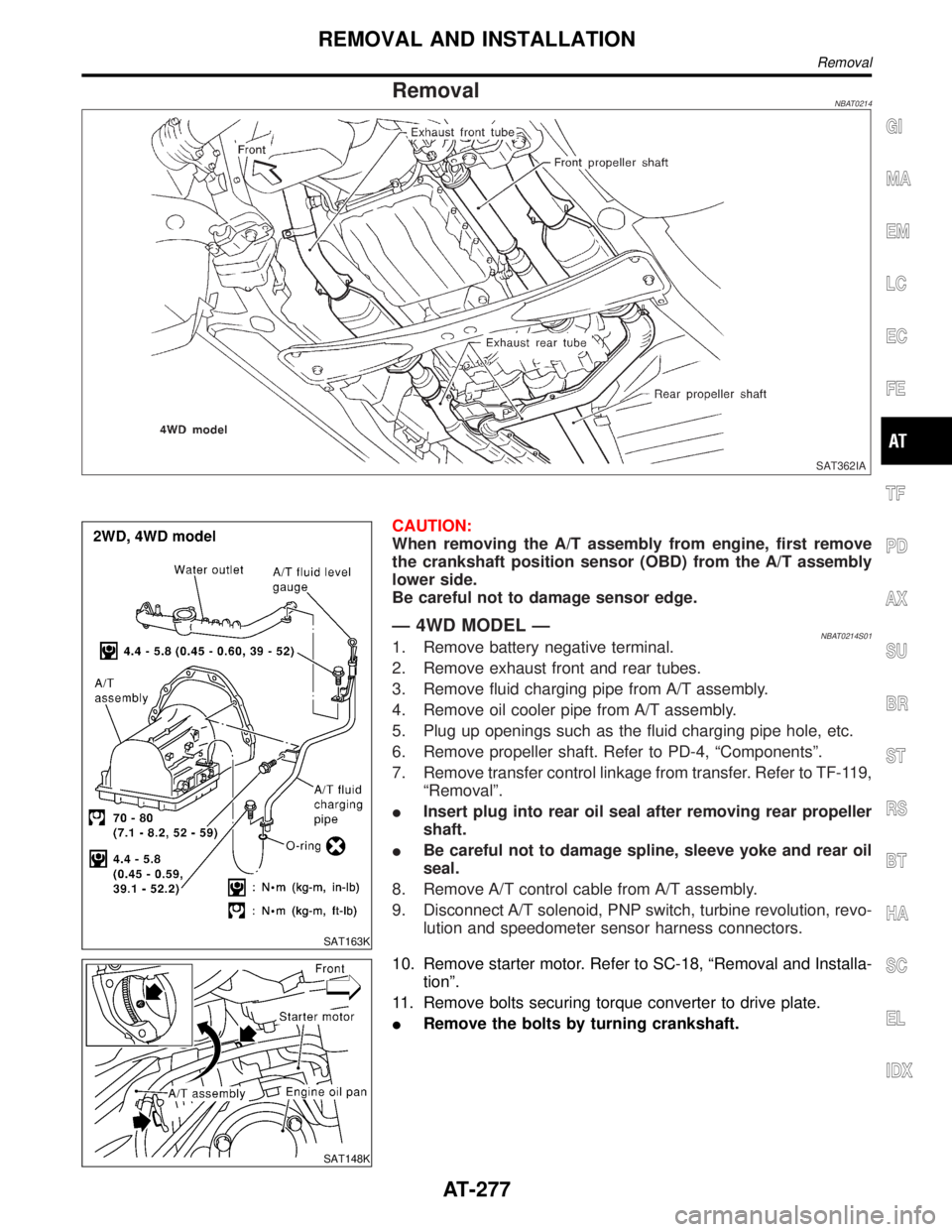
RemovalNBAT0214
SAT362IA
SAT163K
CAUTION:
When removing the A/T assembly from engine, first remove
the crankshaft position sensor (OBD) from the A/T assembly
lower side.
Be careful not to damage sensor edge.
Ð 4WD MODEL ÐNBAT0214S011. Remove battery negative terminal.
2. Remove exhaust front and rear tubes.
3. Remove fluid charging pipe from A/T assembly.
4. Remove oil cooler pipe from A/T assembly.
5. Plug up openings such as the fluid charging pipe hole, etc.
6. Remove propeller shaft. Refer to PD-4, ªComponentsº.
7. Remove transfer control linkage from transfer. Refer to TF-119,
ªRemovalº.
IInsert plug into rear oil seal after removing rear propeller
shaft.
IBe careful not to damage spline, sleeve yoke and rear oil
seal.
8. Remove A/T control cable from A/T assembly.
9. Disconnect A/T solenoid, PNP switch, turbine revolution, revo-
lution and speedometer sensor harness connectors.
SAT148K
10. Remove starter motor. Refer to SC-18, ªRemoval and Installa-
tionº.
11. Remove bolts securing torque converter to drive plate.
IRemove the bolts by turning crankshaft.
GI
MA
EM
LC
EC
FE
TF
PD
AX
SU
BR
ST
RS
BT
HA
SC
EL
IDX
REMOVAL AND INSTALLATION
Removal
AT-277
Page 283 of 2395
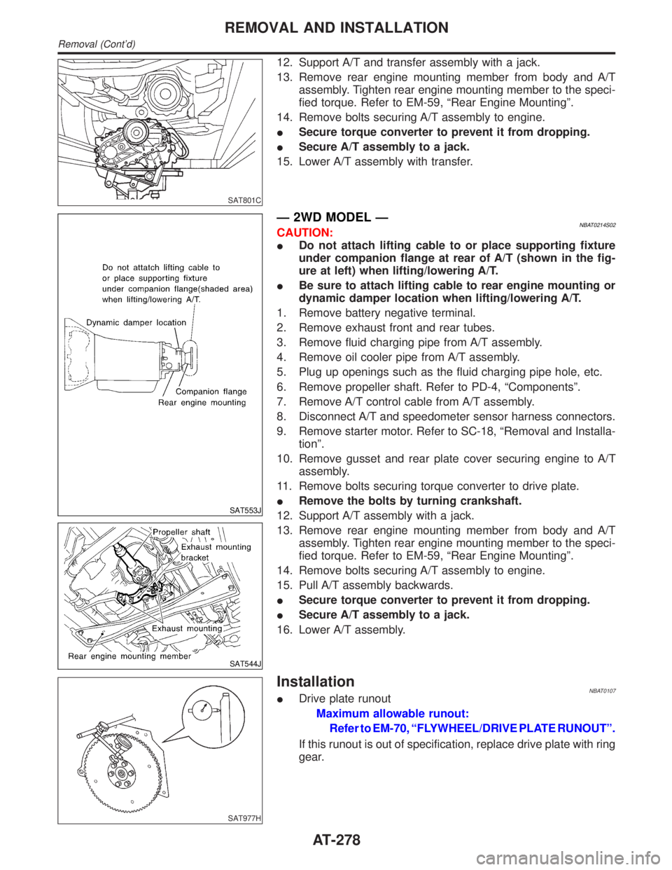
SAT801C
12. Support A/T and transfer assembly with a jack.
13. Remove rear engine mounting member from body and A/T
assembly. Tighten rear engine mounting member to the speci-
fied torque. Refer to EM-59, ªRear Engine Mountingº.
14. Remove bolts securing A/T assembly to engine.
ISecure torque converter to prevent it from dropping.
ISecure A/T assembly to a jack.
15. Lower A/T assembly with transfer.
SAT553J
SAT544J
Ð 2WD MODEL ÐNBAT0214S02CAUTION:
IDo not attach lifting cable to or place supporting fixture
under companion flange at rear of A/T (shown in the fig-
ure at left) when lifting/lowering A/T.
IBe sure to attach lifting cable to rear engine mounting or
dynamic damper location when lifting/lowering A/T.
1. Remove battery negative terminal.
2. Remove exhaust front and rear tubes.
3. Remove fluid charging pipe from A/T assembly.
4. Remove oil cooler pipe from A/T assembly.
5. Plug up openings such as the fluid charging pipe hole, etc.
6. Remove propeller shaft. Refer to PD-4, ªComponentsº.
7. Remove A/T control cable from A/T assembly.
8. Disconnect A/T and speedometer sensor harness connectors.
9. Remove starter motor. Refer to SC-18, ªRemoval and Installa-
tionº.
10. Remove gusset and rear plate cover securing engine to A/T
assembly.
11. Remove bolts securing torque converter to drive plate.
IRemove the bolts by turning crankshaft.
12. Support A/T assembly with a jack.
13. Remove rear engine mounting member from body and A/T
assembly. Tighten rear engine mounting member to the speci-
fied torque. Refer to EM-59, ªRear Engine Mountingº.
14. Remove bolts securing A/T assembly to engine.
15. Pull A/T assembly backwards.
ISecure torque converter to prevent it from dropping.
ISecure A/T assembly to a jack.
16. Lower A/T assembly.
SAT977H
InstallationNBAT0107IDrive plate runout
Maximum allowable runout:
Refer to EM-70, ªFLYWHEEL/DRIVE PLATE RUNOUTº.
If this runout is out of specification, replace drive plate with ring
gear.
REMOVAL AND INSTALLATION
Removal (Cont'd)
AT-278
Page 284 of 2395
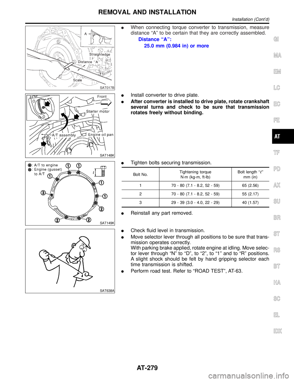
SAT017B
IWhen connecting torque converter to transmission, measure
distance ªAº to be certain that they are correctly assembled.
Distance ªAº:
25.0 mm (0.984 in) or more
SAT148K
IInstall converter to drive plate.
IAfter converter is installed to drive plate, rotate crankshaft
several turns and check to be sure that transmission
rotates freely without binding.
SAT149K
ITighten bolts securing transmission.
Bolt No.Tightening torque
N´m (kg-m, ft-lb)Bolt length ªº
mm (in)
1 70 - 80 (7.1 - 8.2, 52 - 59) 65 (2.56)
2 70 - 80 (7.1 - 8.2, 52 - 59) 55 (2.17)
3 29 - 39 (3.0 - 4.0, 22 - 29) 40 (1.57)
IReinstall any part removed.
SAT638A
ICheck fluid level in transmission.
IMove selector lever through all positions to be sure that trans-
mission operates correctly.
With parking brake applied, rotate engine at idling. Move selec-
tor lever through ªNº to ªDº, to ª2º, to ª1º and to ªRº positions.
A slight shock should be felt by hand gripping selector each
time transmission is shifted.
IPerform road test. Refer to ªROAD TESTº, AT-63.
GI
MA
EM
LC
EC
FE
TF
PD
AX
SU
BR
ST
RS
BT
HA
SC
EL
IDX
REMOVAL AND INSTALLATION
Installation (Cont'd)
AT-279
Page 285 of 2395

AIR BREATHER HOSENBAT0107S01
SAT152K
SAT153K
REMOVAL AND INSTALLATION
Installation (Cont'd)
AT-280
Page 312 of 2395

Control Valve Upper Body
COMPONENTSNBAT0120
SAT142JA
Apply ATF to all components before their installation.
Numbers preceding valve springs correspond with those shown in SDS on page AT-357.
GI
MA
EM
LC
EC
FE
TF
PD
AX
SU
BR
ST
RS
BT
HA
SC
EL
IDX
REPAIR FOR COMPONENT PARTS
Control Valve Upper Body
AT-307
Page 317 of 2395

Control Valve Lower Body
COMPONENTSNBAT0124
SAT966I
Apply ATF to all components before their installation.
Numbers preceding valve springs correspond with those shown in SDS on page AT-357.
REPAIR FOR COMPONENT PARTS
Control Valve Lower Body
AT-312