Idle air INFINITI QX4 2001 Factory Service Manual
[x] Cancel search | Manufacturer: INFINITI, Model Year: 2001, Model line: QX4, Model: INFINITI QX4 2001Pages: 2395, PDF Size: 43.2 MB
Page 1146 of 2395

SEF018Z
COMPONENT DESCRIPTIONNBEC0596S02Power ValveNBEC0596S0201The power valve is installed in intake manifold collector and used
to control the suction passage of the variable induction air control
system. It is set in the fully closed or fully opened position by the
power valve actuator operated by the vacuum stored in the surge
tank. The vacuum in the surge tank is controlled by the VIAS con-
trol solenoid valve.
SEF019Z
VIAS Control Solenoid ValveNBEC0596S0202The VIAS control solenoid valve cuts the intake manifold vacuum
signal for power valve control. It responds to ON/OFF signals from
the ECM. When the solenoid is off, the vacuum signal from the
intake manifold is cut. When the ECM sends an ON signal the coil
pulls the plunger downward and feeds the vacuum signal to the
power valve actuator.
ECM Terminals and Reference ValueNBEC0684Specification data are reference values and are measured between each terminal and ground.
CAUTION:
Do not use ECM ground terminals when measuring input/output voltage. Doing so may result in dam-
age to the ECM's transistor. Use a ground other than ECM terminals, such as the ground.
TERMI-
NAL
NO.WIRE
COLORITEM CONDITION DATA (DC Voltage)
16 Y/GVIAS control solenoid
valve[Engine is running]
IIdle speedBATTERY VOLTAGE
(11 - 14V)
[Engine is running]
IEngine speed is above 5,000 rpm.0 - 1.0V
GI
MA
EM
LC
FE
AT
TF
PD
AX
SU
BR
ST
RS
BT
HA
SC
EL
IDX
VARIABLE INDUCTION AIR CONTROL SYSTEM (VIAS)
Description (Cont'd)
EC-611
Page 1151 of 2395

SEF375Z
Component DescriptionNBEC0383The fuel injector is a small, precise solenoid valve. When the ECM
supplies a ground to the injector circuit, the coil in the injector is
energized. The energized coil pulls the needle valve back and
allows fuel to flow through the injector into the intake manifold. The
amount of fuel injected depends upon the injection pulse duration.
Pulse duration is the length of time the injector remains open. The
ECM controls the injection pulse duration based on engine fuel
needs.
CONSULT-II Reference Value in Data Monitor
Mode
NBEC0384Specification data are reference values.
MONITOR ITEM CONDITION SPECIFICATION
INJ PULSE-B2
INJ PULSE-B1IEngine: After warming up
IAir conditioner switch: ªOFFº
IShift lever: ªNº
INo-loadIdle 2.4 - 3.2 msec
2,000 rpm 1.9 - 2.8 msec
B/FUEL SCHDL dittoIdle 2.0 - 3.2 msec
2,000 rpm 1.4 - 2.6 msec
ECM Terminals and Reference ValueNBEC0685Specification data are reference values and are measured between each terminal and ground.
CAUTION:
Do not use ECM ground terminals when measuring input/output voltage. Doing so may result in dam-
age to the ECM's transistor. Use a ground other than ECM terminals, such as the ground.
TERMI-
NAL
NO.WIRE
COLORITEM CONDITION DATA (DC Voltage)
101
102
103
104
105
107R/B
L/W
R/W
PU/R
R/Y
R/LInjector No. 1
Injector No. 5
Injector No. 2
Injector No. 6
Injector No. 3
Injector No. 4[Engine is running]
IIdle speedBATTERY VOLTAGE
(11 - 14V)
INJECTOR
Component Description
EC-616
Page 1174 of 2395
SEF029Z
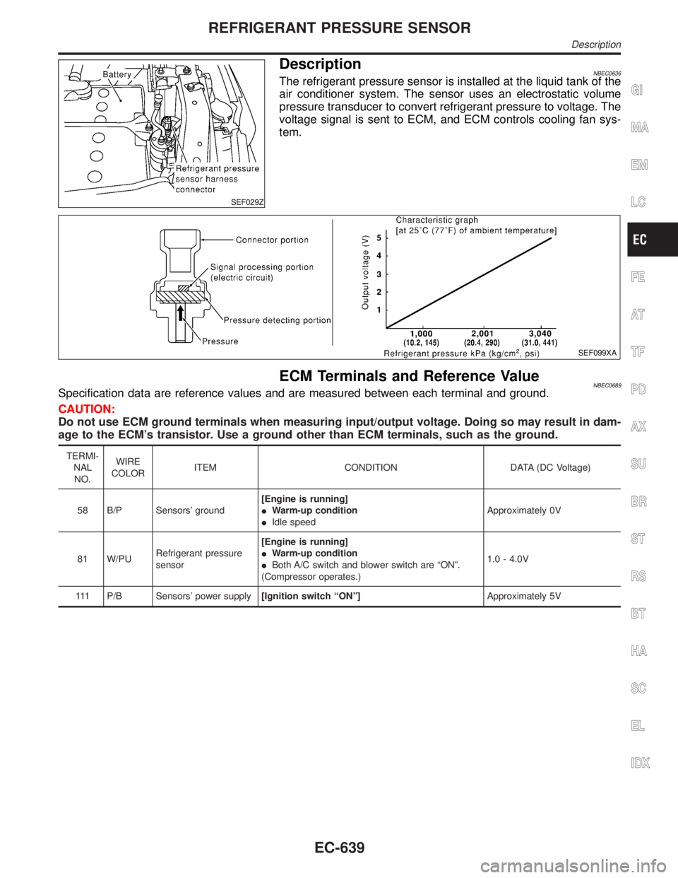
DescriptionNBEC0636The refrigerant pressure sensor is installed at the liquid tank of the
air conditioner system. The sensor uses an electrostatic volume
pressure transducer to convert refrigerant pressure to voltage. The
voltage signal is sent to ECM, and ECM controls cooling fan sys-
tem.
SEF099XA
ECM Terminals and Reference ValueNBEC0689Specification data are reference values and are measured between each terminal and ground.
CAUTION:
Do not use ECM ground terminals when measuring input/output voltage. Doing so may result in dam-
age to the ECM's transistor. Use a ground other than ECM terminals, such as the ground.
TERMI-
NAL
NO.WIRE
COLORITEM CONDITION DATA (DC Voltage)
58 B/P Sensors' ground[Engine is running]
IWarm-up condition
IIdle speedApproximately 0V
81 W/PURefrigerant pressure
sensor[Engine is running]
IWarm-up condition
IBoth A/C switch and blower switch are ªONº.
(Compressor operates.)1.0 - 4.0V
111 P/B Sensors' power supply[Ignition switch ªONº]Approximately 5V
GI
MA
EM
LC
FE
AT
TF
PD
AX
SU
BR
ST
RS
BT
HA
SC
EL
IDX
REFRIGERANT PRESSURE SENSOR
Description
EC-639
Page 1184 of 2395
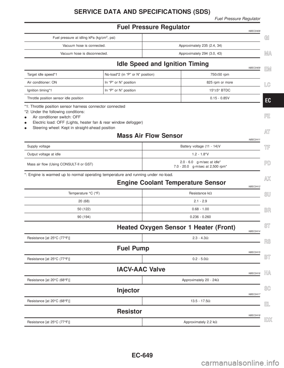
Fuel Pressure RegulatorNBEC0408
Fuel pressure at idling kPa (kg/cm2, psi)
Vacuum hose is connected. Approximately 235 (2.4, 34)
Vacuum hose is disconnected. Approximately 294 (3.0, 43)
Idle Speed and Ignition TimingNBEC0409
Target idle speed*1 No-load*2 (in ªPº or Nº position) 750±50 rpm
Air conditioner: ON In ªPº or Nº position 825 rpm or more
Ignition timing*1 In ªPº or Nº position 15ɱ5É BTDC
Throttle position sensor idle position0.15 - 0.85V
*1: Throttle position sensor harness connector connected
*2: Under the following conditions:
IAir conditioner switch: OFF
IElectric load: OFF (Lights, heater fan & rear window defogger)
ISteering wheel: Kept in straight-ahead position
Mass Air Flow SensorNBEC0411
Supply voltageBattery voltage (11 - 14)V
Output voltage at idle1.2 - 1.8*V
Mass air flow (Using CONSULT-II or GST)2.0 - 6.0 g´m/sec at idle*
7.0 - 20.0 g´m/sec at 2,500 rpm*
*: Engine is warmed up to normal operating temperature and running under no-load.
Engine Coolant Temperature SensorNBEC0412
Temperature ÉC (ÉF) Resistance kW
20 (68) 2.1 - 2.9
50 (122) 0.68 - 1.00
90 (194) 0.236 - 0.260
Heated Oxygen Sensor 1 Heater (Front)NBEC0414
Resistance [at 25ÉC (77ÉF)]2.3 - 4.3W
Fuel PumpNBEC0415
Resistance [at 25ÉC (77ÉF)]0.2 - 5.0W
IACV-AAC ValveNBEC0416
Resistance [at 20ÉC (68ÉF)]Approximately 20 - 24W
InjectorNBEC0417
Resistance [at 20ÉC (68ÉF)]13.5 - 17.5W
ResistorNBEC0418
Resistance [at 25ÉC (77ÉF)]Approximately 2.2 kW
GI
MA
EM
LC
FE
AT
TF
PD
AX
SU
BR
ST
RS
BT
HA
SC
EL
IDX
SERVICE DATA AND SPECIFICATIONS (SDS)
Fuel Pressure Regulator
EC-649
Page 1185 of 2395

Throttle Position SensorNBEC0419
Throttle valve conditionsVoltage
(at normal operating temperature,
engine off, ignition switch ON,
throttle opener disengaged)
Completely closed (a)0.15 - 0.85V
Partially openBetween (a) and (b)
Completely open (b)3.5 - 4.7V
Calculated Load ValueNBEC0420
Calculated load value % (Using CONSULT-II or GST)
At idle14.0 - 33.0
At 2,500 rpm12.0 - 25.0
Intake Air Temperature SensorNBEC0421
Temperature ÉC (ÉF) Resistance kW
20 (68)2.1 - 2.9
80 (176)0.27 - 0.38
Heated Oxygen Sensor 2 Heater (Rear)NBEC0422
Resistance [at 25ÉC (77ÉF)]2.3 - 4.3W
Crankshaft Position Sensor (REF)NBEC0423
Resistance [at 20ÉC (68ÉF)]470 - 570W
Fuel Tank Temperature SensorNBEC0424
Temperature ÉC (ÉF) Resistance kW
20 (68)2.3 - 2.7
50 (122)0.79 - 0.90
Camshaft Position Sensor (PHASE)NBEC0639
Resistance [at 20ÉC (68ÉF)]HITACHI make 1,440 - 1,760W
MITSUBISHI make 2,090 - 2,550W
SERVICE DATA AND SPECIFICATIONS (SDS)
Throttle Position Sensor
EC-650
Page 1652 of 2395
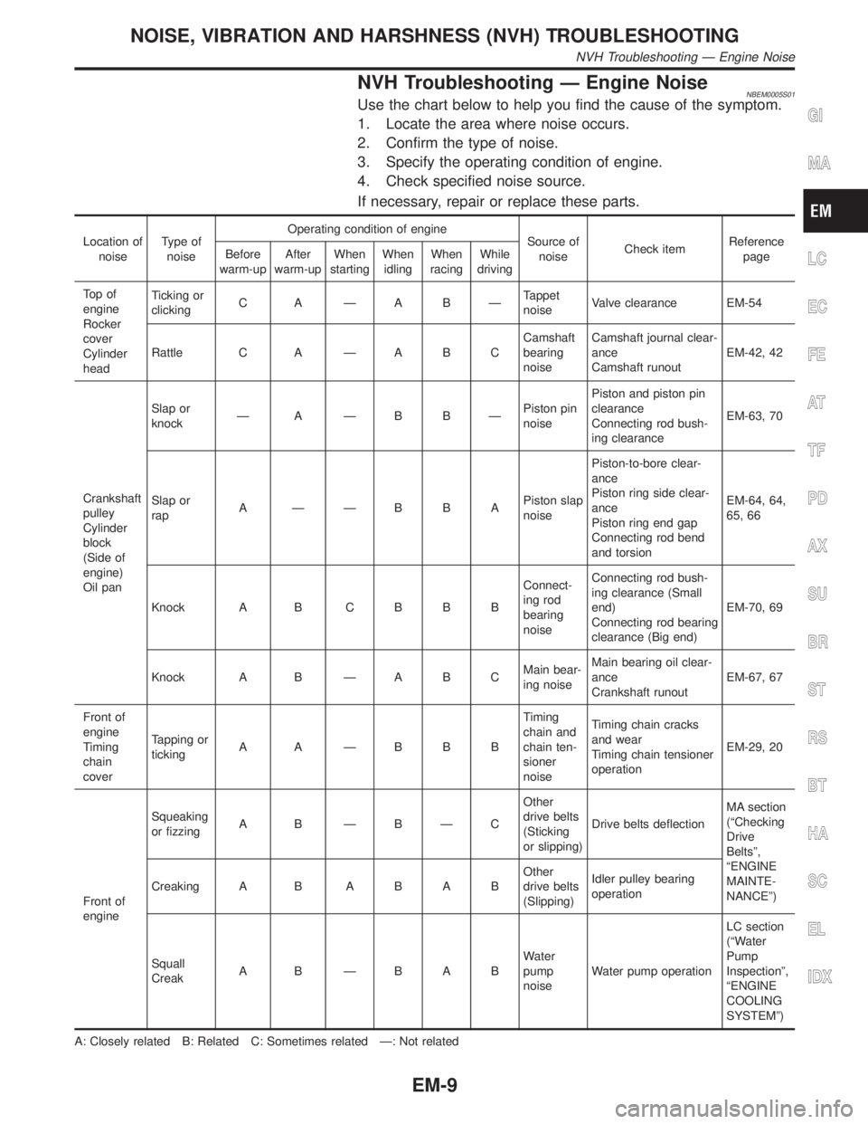
NVH Troubleshooting Ð Engine NoiseNBEM0005S01Use the chart below to help you find the cause of the symptom.
1. Locate the area where noise occurs.
2. Confirm the type of noise.
3. Specify the operating condition of engine.
4. Check specified noise source.
If necessary, repair or replace these parts.
Location of
noiseType of
noiseOperating condition of engine
Source of
noiseCheck itemReference
page Before
warm-upAfter
warm-upWhen
startingWhen
idlingWhen
racingWhile
driving
To p o f
engine
Rocker
cover
Cylinder
headTicking or
clickingC A ÐA BÐTappet
noiseValve clearance EM-54
Rattle C A Ð A B CCamshaft
bearing
noiseCamshaft journal clear-
ance
Camshaft runoutEM-42, 42
Crankshaft
pulley
Cylinder
block
(Side of
engine)
Oil panSlap or
knockÐ A ÐB BÐPiston pin
noisePiston and piston pin
clearance
Connecting rod bush-
ing clearanceEM-63, 70
Slap or
rapA ÐÐBBAPiston slap
noisePiston-to-bore clear-
ance
Piston ring side clear-
ance
Piston ring end gap
Connecting rod bend
and torsionEM-64, 64,
65, 66
Knock A B C B B BConnect-
ing rod
bearing
noiseConnecting rod bush-
ing clearance (Small
end)
Connecting rod bearing
clearance (Big end)EM-70, 69
Knock A B Ð A B CMain bear-
ing noiseMain bearing oil clear-
ance
Crankshaft runoutEM-67, 67
Front of
engine
Timing
chain
coverTapping or
tickingA A ÐBBBTiming
chain and
chain ten-
sioner
noiseTiming chain cracks
and wear
Timing chain tensioner
operationEM-29, 20
Front of
engineSqueaking
or fizzingA B ÐBÐCOther
drive belts
(Sticking
or slipping)Drive belts deflectionMA section
(ªChecking
Drive
Beltsº,
ªENGINE
MAINTE-
NANCEº) Creaking A BABABOther
drive belts
(Slipping)Idler pulley bearing
operation
Squall
CreakA B ÐBABWater
pump
noiseWater pump operationLC section
(ªWater
Pump
Inspectionº,
ªENGINE
COOLING
SYSTEMº)
A: Closely related B: Related C: Sometimes related Ð: Not related
GI
MA
LC
EC
FE
AT
TF
PD
AX
SU
BR
ST
RS
BT
HA
SC
EL
IDX
NOISE, VIBRATION AND HARSHNESS (NVH) TROUBLESHOOTING
NVH Troubleshooting Ð Engine Noise
EM-9
Page 1666 of 2395
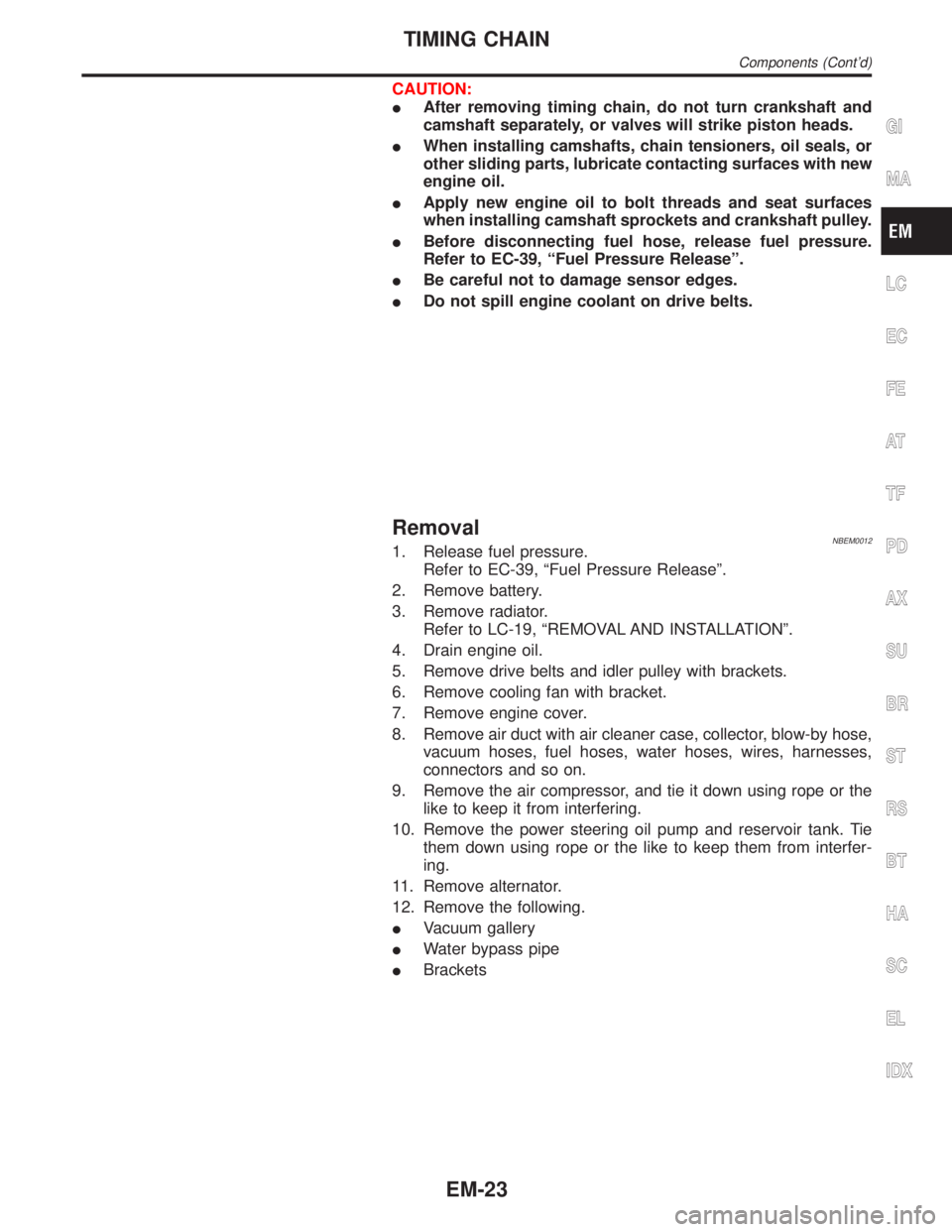
CAUTION:
IAfter removing timing chain, do not turn crankshaft and
camshaft separately, or valves will strike piston heads.
IWhen installing camshafts, chain tensioners, oil seals, or
other sliding parts, lubricate contacting surfaces with new
engine oil.
IApply new engine oil to bolt threads and seat surfaces
when installing camshaft sprockets and crankshaft pulley.
IBefore disconnecting fuel hose, release fuel pressure.
Refer to EC-39, ªFuel Pressure Releaseº.
IBe careful not to damage sensor edges.
IDo not spill engine coolant on drive belts.
RemovalNBEM00121. Release fuel pressure.
Refer to EC-39, ªFuel Pressure Releaseº.
2. Remove battery.
3. Remove radiator.
Refer to LC-19, ªREMOVAL AND INSTALLATIONº.
4. Drain engine oil.
5. Remove drive belts and idler pulley with brackets.
6. Remove cooling fan with bracket.
7. Remove engine cover.
8. Remove air duct with air cleaner case, collector, blow-by hose,
vacuum hoses, fuel hoses, water hoses, wires, harnesses,
connectors and so on.
9. Remove the air compressor, and tie it down using rope or the
like to keep it from interfering.
10. Remove the power steering oil pump and reservoir tank. Tie
them down using rope or the like to keep them from interfer-
ing.
11. Remove alternator.
12. Remove the following.
IVacuum gallery
IWater bypass pipe
IBrackets
GI
MA
LC
EC
FE
AT
TF
PD
AX
SU
BR
ST
RS
BT
HA
SC
EL
IDX
TIMING CHAIN
Components (Cont'd)
EM-23
Page 1745 of 2395
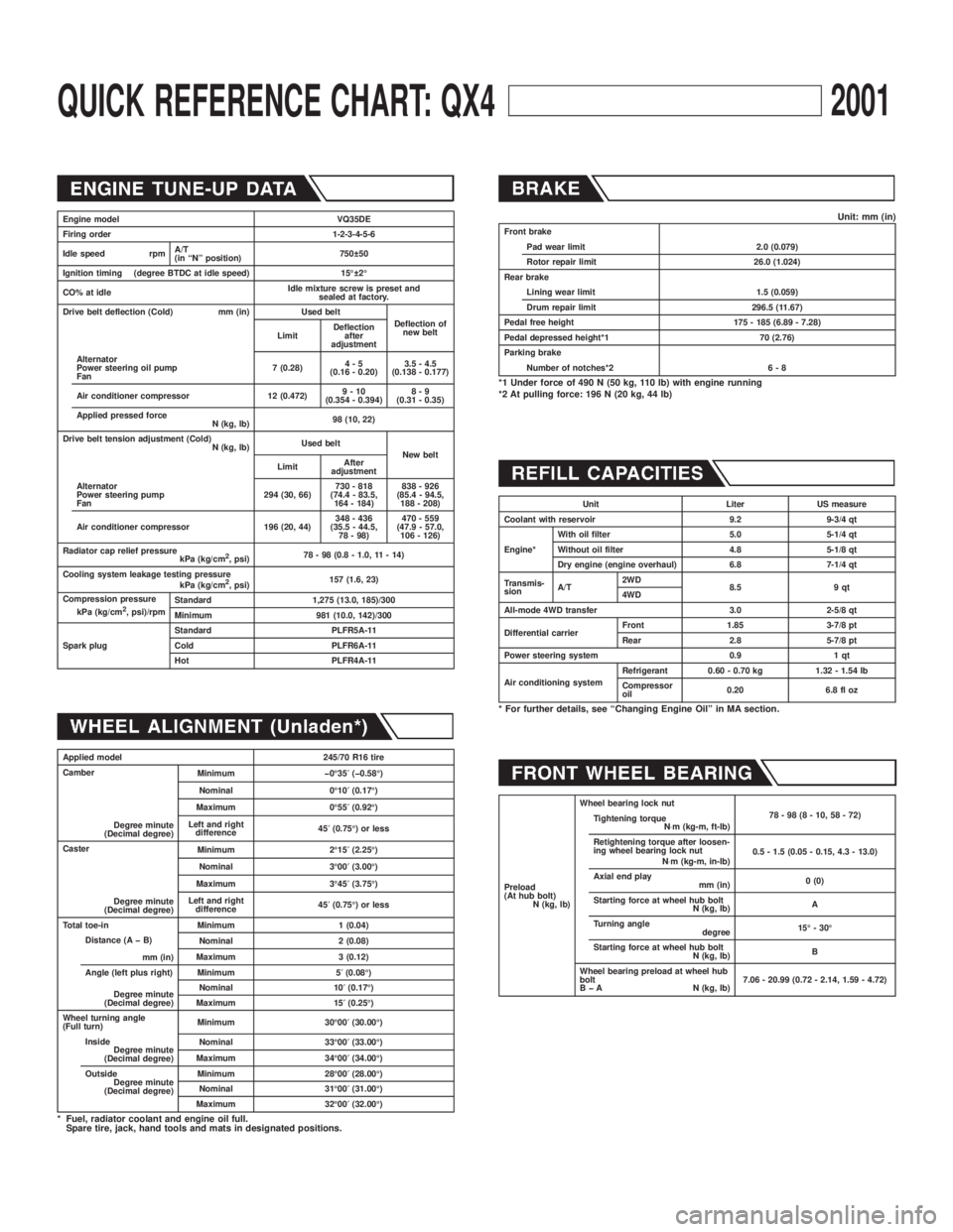
QUICK REFERENCE CHART: QX42001
Engine model VQ35DE
Firing order 1-2-3-4-5-6
Idle speed rpmA/T
(in ªNº position)750 50
Ignition timing (degree BTDC at idle speed) 15É 2É
CO% at idleIdle mixture screw is preset and
sealed at factory.
Drive belt deflection (Cold) mm (in) Used belt
Deflection of
new belt
LimitDeflection
after
adjustment
Alternator
Power steering oil pump
Fan7 (0.28)4-5
(0.16 - 0.20)3.5 - 4.5
(0.138 - 0.177)
Air conditioner compressor 12 (0.472)9-10
(0.354 - 0.394)8-9
(0.31 - 0.35)
Applied pressed force
N (kg, lb)98 (10, 22)
Drive belt tension adjustment (Cold)
N (kg, lb)Used belt
New belt
LimitAfter
adjustment
Alternator
Power steering pump
Fan294 (30, 66)730 - 818
(74.4 - 83.5,
164 - 184)838 - 926
(85.4 - 94.5,
188 - 208)
Air conditioner compressor 196 (20, 44)348 - 436
(35.5 - 44.5,
78 - 98)470 - 559
(47.9 - 57.0,
106 - 126)
Radiator cap relief pressure
kPa (kg/cm
2, psi)78 - 98 (0.8 - 1.0, 11 - 14)
Cooling system leakage testing pressure
kPa (kg/cm
2, psi)157 (1.6, 23)
Compression pressure
kPa (kg/cm
2, psi)/rpmStandard 1,275 (13.0, 185)/300
Minimum 981 (10.0, 142)/300
Spark plugStandard PLFR5A-11
Cold PLFR6A-11
Hot PLFR4A-11
Applied model 245/70 R16 tire
Camber
Degree minute
(Decimal degree)Minimum þ0É35¢(þ0.58É)
Nominal 0É10¢(0.17É)
Maximum 0É55¢(0.92É)
Left and right
difference45¢(0.75É) or less
Caster
Degree minute
(Decimal degree)Minimum 2É15¢(2.25É)
Nominal 3É00¢(3.00É)
Maximum 3É45¢(3.75É)
Left and right
difference45¢(0.75É) or less
Total toe-in Minimum 1 (0.04)
Distance (A þ B)
mm (in)Nominal 2 (0.08)
Maximum 3 (0.12)
Angle (left plus right)
Degree minute
(Decimal degree)Minimum 5¢(0.08É)
Nominal 10¢(0.17É)
Maximum 15¢(0.25É)
Wheel turning angle
(Full turn)Minimum 30É00¢(30.00É)
Inside
Degree minute
(Decimal degree)Nominal 33É00¢(33.00É)
Maximum 34É00¢(34.00É)
Outside
Degree minute
(Decimal degree)Minimum 28É00¢(28.00É)
Nominal 31É00¢(31.00É)
Maximum 32É00¢(32.00É)
* Fuel, radiator coolant and engine oil full.
Spare tire, jack, hand tools and mats in designated positions.
Unit: mm (in)Front brake
Pad wear limit 2.0 (0.079)
Rotor repair limit 26.0 (1.024)
Rear brake
Lining wear limit 1.5 (0.059)
Drum repair limit 296.5 (11.67)
Pedal free height 175 - 185 (6.89 - 7.28)
Pedal depressed height*1 70 (2.76)
Parking brake
Number of notches*2 6 - 8
*1 Under force of 490 N (50 kg, 110 lb) with engine running
*2 At pulling force: 196 N (20 kg, 44 lb)
Unit Liter US measure
Coolant with reservoir 9.2 9-3/4 qt
Engine*With oil filter 5.0 5-1/4 qt
Without oil filter 4.8 5-1/8 qt
Dry engine (engine overhaul) 6.8 7-1/4 qt
Transmis-
sionA/T2WD
8.5 9 qt
4WD
All-mode 4WD transfer 3.0 2-5/8 qt
Differential carrierFront 1.85 3-7/8 pt
Rear 2.8 5-7/8 pt
Power steering system 0.9 1 qt
Air conditioning systemRefrigerant 0.60 - 0.70 kg 1.32 - 1.54 lb
Compressor
oil0.20 6.8 fl oz
* For further details, see ªChanging Engine Oilº in MA section.
Preload
(At hub bolt)
N (kg, lb)Wheel bearing lock nut
78-98(8-10,58-72)
Tightening torque
N×m (kg-m, ft-lb)
Retightening torque after loosen-
ing wheel bearing lock nut
N×m (kg-m, in-lb)0.5 - 1.5 (0.05 - 0.15, 4.3 - 13.0)
Axial end play
mm (in)0 (0)
Starting force at wheel hub bolt
N (kg, lb)A
Turning angle
degree15É - 30É
Starting force at wheel hub bolt
N (kg, lb)B
Wheel bearing preload at wheel hub
bolt
B þ A N (kg, lb)7.06 - 20.99 (0.72 - 2.14, 1.59 - 4.72)
Page 1796 of 2395
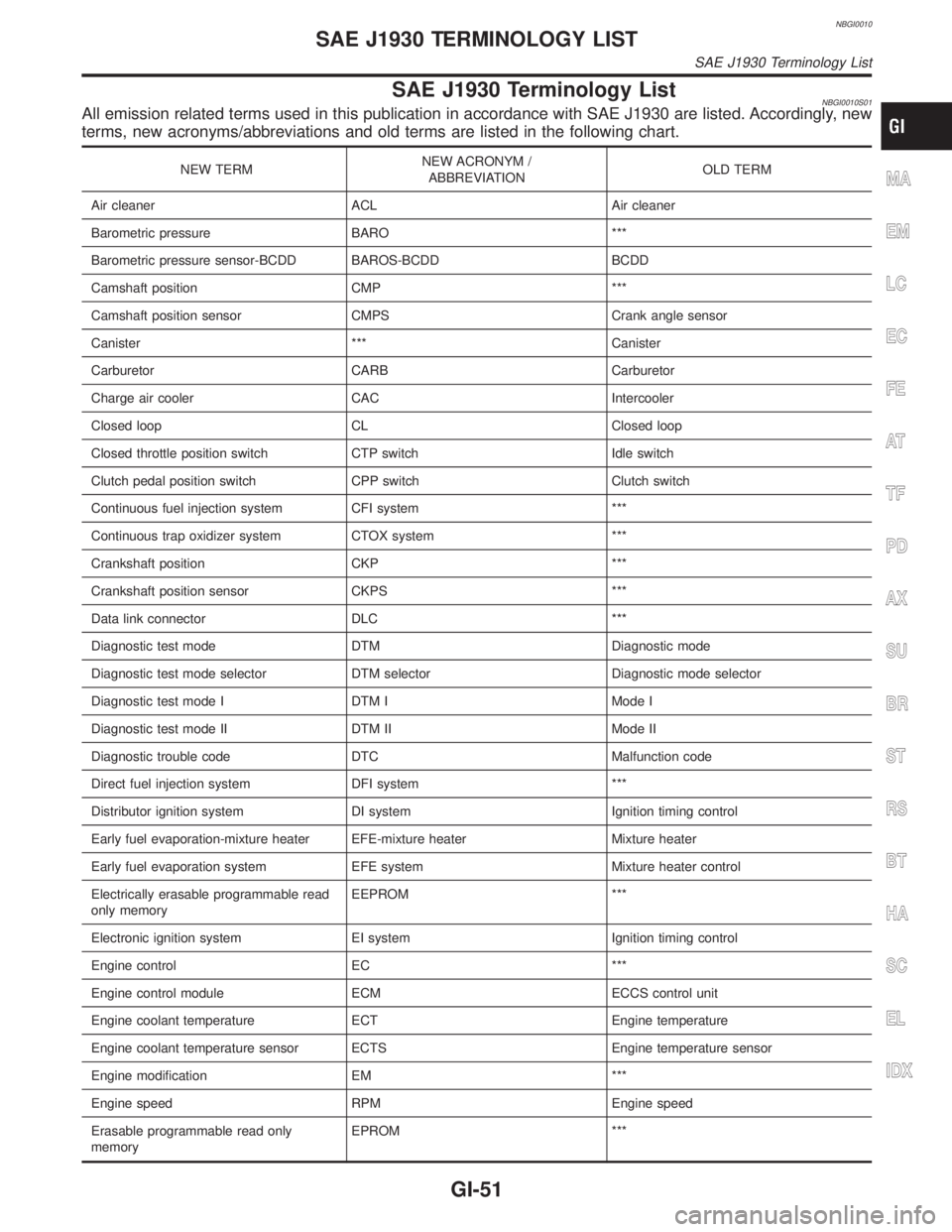
NBGI0010
SAE J1930 Terminology ListNBGI0010S01All emission related terms used in this publication in accordance with SAE J1930 are listed. Accordingly, new
terms, new acronyms/abbreviations and old terms are listed in the following chart.
NEW TERMNEW ACRONYM /
ABBREVIATIONOLD TERM
Air cleaner ACL Air cleaner
Barometric pressure BARO ***
Barometric pressure sensor-BCDD BAROS-BCDD BCDD
Camshaft position CMP ***
Camshaft position sensor CMPS Crank angle sensor
Canister *** Canister
Carburetor CARB Carburetor
Charge air cooler CAC Intercooler
Closed loop CL Closed loop
Closed throttle position switch CTP switch Idle switch
Clutch pedal position switch CPP switch Clutch switch
Continuous fuel injection system CFI system ***
Continuous trap oxidizer system CTOX system ***
Crankshaft position CKP ***
Crankshaft position sensor CKPS ***
Data link connector DLC ***
Diagnostic test mode DTM Diagnostic mode
Diagnostic test mode selector DTM selector Diagnostic mode selector
Diagnostic test mode I DTM I Mode I
Diagnostic test mode II DTM II Mode II
Diagnostic trouble code DTC Malfunction code
Direct fuel injection system DFI system ***
Distributor ignition system DI system Ignition timing control
Early fuel evaporation-mixture heater EFE-mixture heater Mixture heater
Early fuel evaporation system EFE system Mixture heater control
Electrically erasable programmable read
only memoryEEPROM ***
Electronic ignition system EI system Ignition timing control
Engine control EC ***
Engine control module ECM ECCS control unit
Engine coolant temperature ECT Engine temperature
Engine coolant temperature sensor ECTS Engine temperature sensor
Engine modification EM ***
Engine speed RPM Engine speed
Erasable programmable read only
memoryEPROM ***MA
EM
LC
EC
FE
AT
TF
PD
AX
SU
BR
ST
RS
BT
HA
SC
EL
IDX
SAE J1930 TERMINOLOGY LIST
SAE J1930 Terminology List
GI-51
Page 1797 of 2395

NEW TERMNEW ACRONYM /
ABBREVIATIONOLD TERM
Evaporative emission canister EVAP canister Canister
Evaporative emission system EVAP system Canister control solenoid valve
Exhaust gas recirculation valve EGR valve EGR valve
Exhaust gas recirculation control-BPT
valveEGRC-BPT valve BPT valve
Exhaust gas recirculation control-solenoid
valveEGRC-solenoid valve EGR control solenoid valve
Exhaust gas recirculation temperature
sensorEGRT sensor Exhaust gas temperature sensor
EGR temperature sensor
Flash electrically erasable programmable
read only memoryFEEPROM ***
Flash erasable programmable read only
memoryFEPROM ***
Flexible fuel sensor FFS ***
Flexible fuel system FF system ***
Fuel pressure regulator *** Pressure regulator
Fuel pressure regulator control solenoid
valve*** PRVR control solenoid valve
Fuel tank temperature sensor FTT sensor Tank fuel temperature sensor
Fuel trim FT ***
Heated Oxygen sensor HO2S Exhaust gas sensor
Idle air control system IAC system Idle speed control
Idle air control valve-air regulator IACV-air regulator Air regulator
Idle air control valve-auxiliary air control
valveIACV-AAC valve Auxiliary air control (AAC) valve
Idle air control valve-FICD solenoid valve IACV-FICD solenoid valve FICD solenoid valve
Idle air control valve-idle up control sole-
noid valveIACV-idle up control solenoid valve Idle up control solenoid valve
Idle speed control-FI pot ISC-FI pot FI pot
Idle speed control system ISC system ***
Ignition control IC ***
Ignition control module ICM ***
Indirect fuel injection system IFI system ***
Intake air IA Air
Intake air temperature sensor IAT sensor Air temperature sensor
Knock *** Detonation
Knock sensor KS Detonation sensor
Malfunction indicator lamp MIL Check engine light
Manifold absolute pressure MAP ***
Manifold absolute pressure sensor MAPS ***
SAE J1930 TERMINOLOGY LIST
SAE J1930 Terminology List (Cont'd)
GI-52