Idle air INFINITI QX4 2001 Factory Manual PDF
[x] Cancel search | Manufacturer: INFINITI, Model Year: 2001, Model line: QX4, Model: INFINITI QX4 2001Pages: 2395, PDF Size: 43.2 MB
Page 841 of 2395
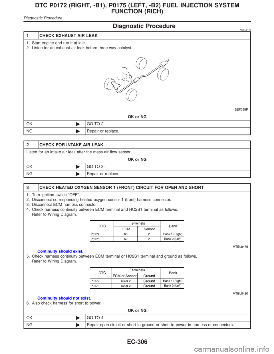
Diagnostic ProcedureNBEC0176
1 CHECK EXHAUST AIR LEAK
1. Start engine and run it at idle.
2. Listen for an exhaust air leak before three way catalyst.
SEF099P
OK or NG
OK©GO TO 2.
NG©Repair or replace.
2 CHECK FOR INTAKE AIR LEAK
Listen for an intake air leak after the mass air flow sensor.
OK or NG
OK©GO TO 3.
NG©Repair or replace.
3 CHECK HEATED OXYGEN SENSOR 1 (FRONT) CIRCUIT FOR OPEN AND SHORT
1. Turn ignition switch ªOFFº.
2. Disconnect corresponding heated oxygen sensor 1 (front) harness connector.
3. Disconnect ECM harness connector.
4. Check harness continuity between ECM terminal and HO2S1 terminal as follows.
Refer to Wiring Diagram.
MTBL0479
Continuity should exist.
5. Check harness continuity between ECM terminal or HO2S1 terminal and ground as follows.
Refer to Wiring Diagram.
MTBL0480
Continuity should not exist.
6. Also check harness for short to power.
OK or NG
OK©GO TO 4.
NG©Repair open circuit or short to ground or short to power in harness or connectors.
DTC P0172 (RIGHT, -B1), P0175 (LEFT, -B2) FUEL INJECTION SYSTEM
FUNCTION (RICH)
Diagnostic Procedure
EC-306
Page 850 of 2395

of 2 liters per minute like pouring coolant from a kettle. Be sure
to use coolant with the proper mixture ratio. Refer to MA-12,
ªAnti-freeze Coolant Mixture Ratioº.
b) After refilling coolant, run engine to ensure that no water-flow
noise is emitted.
c) After checking or replacing coolant, go to step 3 below.
2) Ask the customer if engine coolant has been added. If it has
been added, go to ªDiagnostic Procedureº, EC-316. After
repair, go to the next step.
3) Start engine and let it idle.
4) Make sure that A/C switch is ªOFFº and air conditioner is not
operating. If NG, check air conditioner circuit. Refer to HA-30
or HA-35, ªTROUBLE DIAGNOSESº. After repair, go to the
next step.
5) Check for blocked coolant passage.
a) Warm up engine to normal operating temperature, then grasp
radiator upper hose and lower hose and make sure that cool-
ant flows.
If NG, go to ªDiagnostic Procedureº, EC-316. After repair, go
to the next step.
Be extremely careful not to touch any moving or adjacent
parts.
6) Check for blocked radiator air passage.
a) When market fog lamps have been installed, check for dam-
aged fans and clogging in the condenser and radiator.
b) Check the front end for clogging caused by insects or debris.
c) Check for improper fitting of front-end cover, damaged radia-
tor grille or bumper, damaged vehicle front.
If NG, take appropriate action and then go to the next step.
7) Check function of ECT sensor.
Refer to step 7 of ªDiagnostic Procedureº, EC-316.
If NG, replace ECT sensor and go to the next step.
8) Check ignition timing. Refer to basic inspection, EC-101.
Make sure that ignition timing is 15ɱ5É at idle.
If NG, adjust ignition timing and then recheck.
WITH GSTNBEC0612S021) Check the coolant level and mixture ratio (using coolant tester)
in the reservoir tank and radiator.
Allow engine to cool before checking coolant level and
mixture ratio.
IIf the coolant level in the reservoir and/or radiator is below the
proper range, and go to ªDiagnostic Procedureº, EC-316.
IIf the coolant mixture ratio is out of the range of 45 to 55%,
replace the coolant in the following procedure MA-14, ªChang-
ing Engine Coolantº.
a) Fill radiator with coolant up to specified level with a filling speed
of 2 liters per minute like pouring coolant from a kettle. Be sure
to use coolant with the proper mixture ratio. Refer to MA-12,
ªAnti-freeze Coolant Mixture Ratioº.
b) After refilling coolant, run engine to ensure that no water-flow
noise is emitted.
c) After checking or replacing coolant, go to step 3 below.
2) Ask the customer if engine coolant has been added. If it has
been added, go to ªDiagnostic Procedureº, EC-316. After
repair, go to the next step.
3) Start engine and let it idle.
GI
MA
EM
LC
FE
AT
TF
PD
AX
SU
BR
ST
RS
BT
HA
SC
EL
IDX
DTC P0217 COOLANT OVERTEMPERATURE ENRICHMENT PROTECTION
Overall Function Check (Cont'd)
EC-315
Page 851 of 2395
4) Make sure that A/C switch is ªOFFº and air conditioner is not
operating. If NG, check air conditioner circuit. Refer to HA-35
or HA-30, ªTROUBLE DIAGNOSESº. After repair, go to the
next step.
5) Check for blocked coolant passage.
a) Warm up engine to normal operating temperature, then grasp
radiator upper hose and lower hose and make sure that cool-
ant flows.
If NG, go to ªDiagnostic Procedureº, EC-316. After repair, go
to the next step.
Be extremely careful not to touch any moving or adjacent
parts.
6) Check for blocked radiator air passage.
a) When market fog lamps have been installed, check for dam-
aged fans and clogging in the condenser and radiator.
b) Check the front end for clogging caused by insects or debris.
c) Check for improper fitting of front-end cover, damaged radia-
tor grille or bumper, damaged vehicle front.
If NG, take appropriate action and then go to the next step.
7) Check function of ECT sensor.
Refer to step 6 of ªDiagnostic Procedureº, EC-316.
If NG, replace ECT sensor and go to the next step.
8) Check ignition timing. Refer to basic inspection, EC-101.
Make sure that ignition timing is 15ɱ5É at idle.
If NG, adjust ignition timing and then recheck.
Diagnostic ProcedureNBEC0614
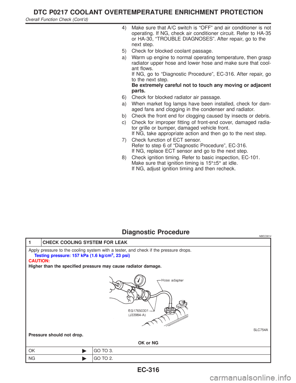
1 CHECK COOLING SYSTEM FOR LEAK
Apply pressure to the cooling system with a tester, and check if the pressure drops.
Testing pressure: 157 kPa (1.6 kg/cm2, 23 psi)
CAUTION:
Higher than the specified pressure may cause radiator damage.
SLC754A
Pressure should not drop.
OK or NG
OK©GO TO 3.
NG©GO TO 2.
DTC P0217 COOLANT OVERTEMPERATURE ENRICHMENT PROTECTION
Overall Function Check (Cont'd)
EC-316
Page 856 of 2395
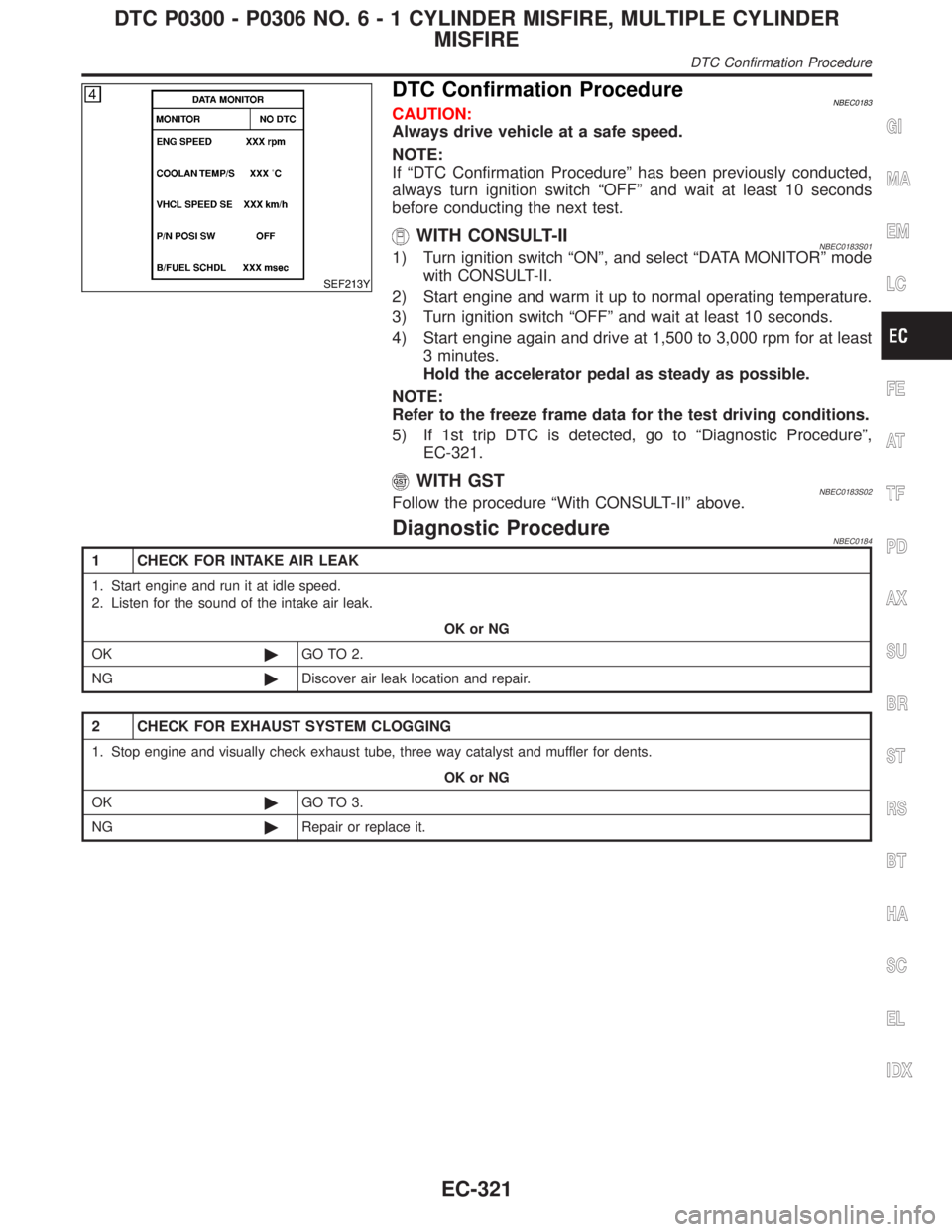
SEF213Y
DTC Confirmation ProcedureNBEC0183CAUTION:
Always drive vehicle at a safe speed.
NOTE:
If ªDTC Confirmation Procedureº has been previously conducted,
always turn ignition switch ªOFFº and wait at least 10 seconds
before conducting the next test.
WITH CONSULT-IINBEC0183S011) Turn ignition switch ªONº, and select ªDATA MONITORº mode
with CONSULT-II.
2) Start engine and warm it up to normal operating temperature.
3) Turn ignition switch ªOFFº and wait at least 10 seconds.
4) Start engine again and drive at 1,500 to 3,000 rpm for at least
3 minutes.
Hold the accelerator pedal as steady as possible.
NOTE:
Refer to the freeze frame data for the test driving conditions.
5) If 1st trip DTC is detected, go to ªDiagnostic Procedureº,
EC-321.
WITH GSTNBEC0183S02Follow the procedure ªWith CONSULT-IIº above.
Diagnostic ProcedureNBEC0184
1 CHECK FOR INTAKE AIR LEAK
1. Start engine and run it at idle speed.
2. Listen for the sound of the intake air leak.
OK or NG
OK©GO TO 2.
NG©Discover air leak location and repair.
2 CHECK FOR EXHAUST SYSTEM CLOGGING
1. Stop engine and visually check exhaust tube, three way catalyst and muffler for dents.
OK or NG
OK©GO TO 3.
NG©Repair or replace it.
GI
MA
EM
LC
FE
AT
TF
PD
AX
SU
BR
ST
RS
BT
HA
SC
EL
IDX
DTC P0300 - P0306 NO.6-1CYLINDER MISFIRE, MULTIPLE CYLINDER
MISFIRE
DTC Confirmation Procedure
EC-321
Page 859 of 2395

8 CHECK FUEL PRESSURE
1. Install all removed parts.
2. Release fuel pressure to zero. Refer to EC-39.
3. Install fuel pressure gauge and check fuel pressure. Refer to EC-39.
At idle:
Approx. 235 kPa (2.4 kg/cm
2, 34 psi)
OK or NG
OK©GO TO 10.
NG©GO TO 9.
9 DETECT MALFUNCTIONING PART
Check the following.
IFuel pump and circuit (Refer to EC-625.)
IFuel pressure regulator (Refer to EC-40.)
IFuel lines (Refer to MA-16, ªChecking Fuel Linesº.)
IFuel filter for clogging
©Repair or replace.
10 CHECK IGNITION TIMING
Check the following items. Refer to ªBasic Inspectionº, EC-101.
MTBL0655
OK or NG
OK (With CONSULT-II)©GO TO 11.
OK (Without CONSULT-
II)©GO TO 12.
NG©Follow the ªBasic Inspectionº.
DTC P0300 - P0306 NO.6-1CYLINDER MISFIRE, MULTIPLE CYLINDER
MISFIRE
Diagnostic Procedure (Cont'd)
EC-324
Page 862 of 2395

14 CHECK MASS AIR FLOW SENSOR
With CONSULT-II
Check mass air flow sensor signal in ªDATA MONITORº mode with CONSULT-II.
2.0 - 6.0 g´m/sec: at idling
7.0 - 20.0 g´m/sec: at 2,500 rpm
With GST
Check mass air flow sensor signal in MODE 1 with GST.
2.0 - 6.0 g´m/sec: at idling
7.0 - 20.0 g´m/sec: at 2,500 rpm
OK or NG
OK©GO TO 15.
NG©Check connectors for rusted terminals or loose connections in the mass air flow sensor
circuit or engine grounds. Refer to EC-150.
15 CHECK SYMPTOM MATRIX CHART
Check items on the rough idle symptom in ªSymptom Matrix Chartº, EC-118.
OK or NG
OK©GO TO 16.
NG©Repair or replace.
16 ERASE THE 1ST TRIP DTC
Erase the 1st trip DTC from the ECM memory after performing the tests. Refer to EC-72.
Some tests may cause a 1st trip DTC to be set.
©GO TO 17.
17 CHECK INTERMITTENT INCIDENT
Refer to ªTROUBLE DIAGNOSIS FOR INTERMITTENT INCIDENTº, EC-140.
©INSPECTION END
GI
MA
EM
LC
FE
AT
TF
PD
AX
SU
BR
ST
RS
BT
HA
SC
EL
IDX
DTC P0300 - P0306 NO.6-1CYLINDER MISFIRE, MULTIPLE CYLINDER
MISFIRE
Diagnostic Procedure (Cont'd)
EC-327
Page 884 of 2395

A: Rear heated oxygen sensor voltage switching fre-
quency
B: Front heated oxygen sensor voltage switching fre-
quency
This ratio should be less than 0.75.
If the ratio is greater than above, it means warm-up three way
catalyst does not operate properly. Go to ªDiagnostic
Procedureº, EC-349.
NOTE:
If the voltage at terminal 62 or 63 does not switch periodically more
than 5 times within 10 seconds at step 5, perform trouble diagno-
sis for ªDTC P0133, P0153º first. (See EC-218.)
Diagnostic ProcedureNBEC0217
1 CHECK EXHAUST SYSTEM
Visually check exhaust tubes and muffler for dent.
OK or NG
OK©GO TO 2.
NG©Repair or replace.
2 CHECK EXHAUST AIR LEAK
1. Start engine and run it at idle.
2. Listen for an exhaust air leak before the warm-up three way catalyst.
SEF099P
OK or NG
OK©GO TO 3.
NG©Repair or replace.
3 CHECK INTAKE AIR LEAK
Listen for an intake air leak after the mass air flow sensor.
OK or NG
OK©GO TO 4.
NG©Repair or replace.
GI
MA
EM
LC
FE
AT
TF
PD
AX
SU
BR
ST
RS
BT
HA
SC
EL
IDX
DTC P0420 (RIGHT BANK, -B1), P0430 (LEFT BANK, -B2) THREE WAY
CATALYST FUNCTION
Overall Function Check (Cont'd)
EC-349
Page 896 of 2395
11 CHECK EVAP CANISTER
Weigh the EVAP canister with the EVAP canister vent control valve attached.
The weight should be less than 1.8 kg (4.0 lb).
OK or NG
OK (With CONSULT-II)©GO TO 13.
OK (Without CONSULT-
II)©GO TO 14.
NG©GO TO 12.
12 DETECT MALFUNCTIONING PART
Check the following.
IEVAP canister for damage
IEVAP hose between EVAP canister and water separator for clogging or poor connection
©Repair hose or replace EVAP canister.
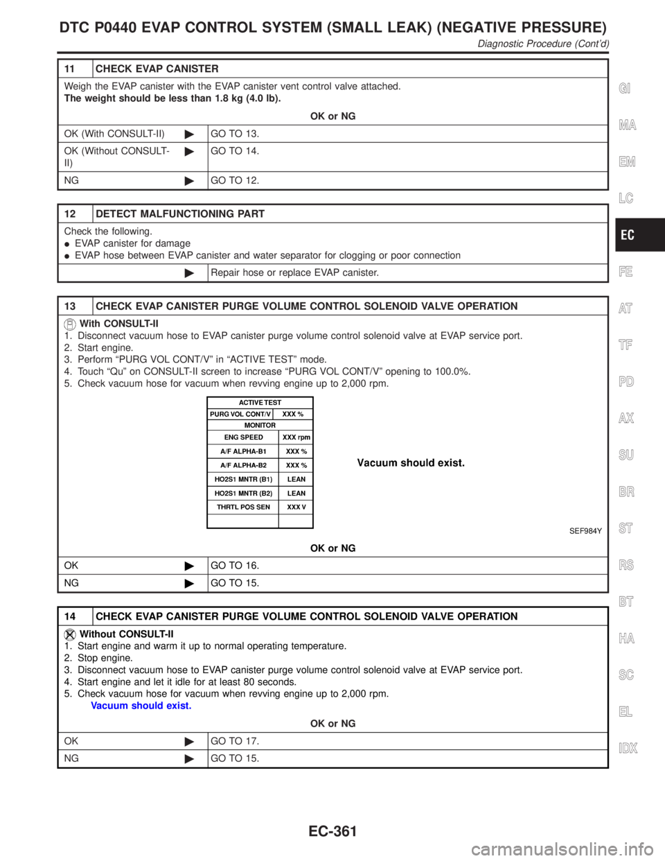
13 CHECK EVAP CANISTER PURGE VOLUME CONTROL SOLENOID VALVE OPERATION
With CONSULT-II
1. Disconnect vacuum hose to EVAP canister purge volume control solenoid valve at EVAP service port.
2. Start engine.
3. Perform ªPURG VOL CONT/Vº in ªACTIVE TESTº mode.
4. Touch ªQuº on CONSULT-II screen to increase ªPURG VOL CONT/Vº opening to 100.0%.
5. Check vacuum hose for vacuum when revving engine up to 2,000 rpm.
SEF984Y
OK or NG
OK©GO TO 16.
NG©GO TO 15.
14 CHECK EVAP CANISTER PURGE VOLUME CONTROL SOLENOID VALVE OPERATION
Without CONSULT-II
1. Start engine and warm it up to normal operating temperature.
2. Stop engine.
3. Disconnect vacuum hose to EVAP canister purge volume control solenoid valve at EVAP service port.
4. Start engine and let it idle for at least 80 seconds.
5. Check vacuum hose for vacuum when revving engine up to 2,000 rpm.
Vacuum should exist.
OK or NG
OK©GO TO 17.
NG©GO TO 15.
GI
MA
EM
LC
FE
AT
TF
PD
AX
SU
BR
ST
RS
BT
HA
SC
EL
IDX
DTC P0440 EVAP CONTROL SYSTEM (SMALL LEAK) (NEGATIVE PRESSURE)
Diagnostic Procedure (Cont'd)
EC-361
Page 902 of 2395
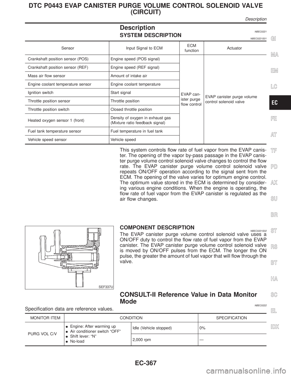
DescriptionNBEC0221SYSTEM DESCRIPTIONNBEC0221S01
Sensor Input Signal to ECMECM
functionActuator
Crankshaft position sensor (POS) Engine speed (POS signal)
EVAP can-
ister purge
flow controlEVAP canister purge volume
control solenoid valve Crankshaft position sensor (REF) Engine speed (REF signal)
Mass air flow sensor Amount of intake air
Engine coolant temperature sensor Engine coolant temperature
Ignition switch Start signal
Throttle position sensor Throttle position
Throttle position switch Closed throttle position
Heated oxygen sensor 1 (front)Density of oxygen in exhaust gas
(Mixture ratio feedback signal)
Fuel tank temperature sensor Fuel temperature in fuel tank
Vehicle speed sensor Vehicle speed
This system controls flow rate of fuel vapor from the EVAP canis-
ter. The opening of the vapor by-pass passage in the EVAP canis-
ter purge volume control solenoid valve changes to control the flow
rate. The EVAP canister purge volume control solenoid valve
repeats ON/OFF operation according to the signal sent from the
ECM. The opening of the valve varies for optimum engine control.
The optimum value stored in the ECM is determined by consider-
ing various engine conditions. When the engine is operating, the
flow rate of fuel vapor from the EVAP canister is regulated as the
air flow changes.
SEF337U
COMPONENT DESCRIPTIONNBEC0221S02The EVAP canister purge volume control solenoid valve uses a
ON/OFF duty to control the flow rate of fuel vapor from the EVAP
canister. The EVAP canister purge volume control solenoid valve
is moved by ON/OFF pulses from the ECM. The longer the ON
pulse, the greater the amount of fuel vapor that will flow through the
valve.
CONSULT-II Reference Value in Data Monitor
Mode
NBEC0222Specification data are reference values.
MONITOR ITEM CONDITION SPECIFICATION
PURG VOL C/VIEngine: After warming up
IAir conditioner switch ªOFFº
IShift lever: ªNº
INo-loadIdle (Vehicle stopped) 0%
2,000 rpm Ð
GI
MA
EM
LC
FE
AT
TF
PD
AX
SU
BR
ST
RS
BT
HA
SC
EL
IDX
DTC P0443 EVAP CANISTER PURGE VOLUME CONTROL SOLENOID VALVE
(CIRCUIT)
Description
EC-367
Page 937 of 2395
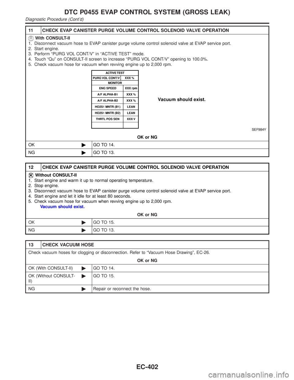
11 CHECK EVAP CANISTER PURGE VOLUME CONTROL SOLENOID VALVE OPERATION
With CONSULT-II
1. Disconnect vacuum hose to EVAP canister purge volume control solenoid valve at EVAP service port.
2. Start engine.
3. Perform ªPURG VOL CONT/Vº in ªACTIVE TESTº mode.
4. Touch ªQuº on CONSULT-II screen to increase ªPURG VOL CONT/Vº opening to 100.0%.
5. Check vacuum hose for vacuum when revving engine up to 2,000 rpm.
SEF984Y
OK or NG
OK©GO TO 14.
NG©GO TO 13.
12 CHECK EVAP CANISTER PURGE VOLUME CONTROL SOLENOID VALVE OPERATION
Without CONSULT-II
1. Start engine and warm it up to normal operating temperature.
2. Stop engine.
3. Disconnect vacuum hose to EVAP canister purge volume control solenoid valve at EVAP service port.
4. Start engine and let it idle for at least 80 seconds.
5. Check vacuum hose for vacuum when revving engine up to 2,000 rpm.
Vacuum should exist.
OK or NG
OK©GO TO 15.
NG©GO TO 13.
13 CHECK VACUUM HOSE
Check vacuum hoses for clogging or disconnection. Refer to ªVacuum Hose Drawingº, EC-26.
OK or NG
OK (With CONSULT-II)©GO TO 14.
OK (Without CONSULT-
II)©GO TO 15.
NG©Repair or reconnect the hose.
DTC P0455 EVAP CONTROL SYSTEM (GROSS LEAK)
Diagnostic Procedure (Cont'd)
EC-402