clutch INFINITI QX4 2001 Factory Service Manual
[x] Cancel search | Manufacturer: INFINITI, Model Year: 2001, Model line: QX4, Model: INFINITI QX4 2001Pages: 2395, PDF Size: 43.2 MB
Page 353 of 2395

SAT978A
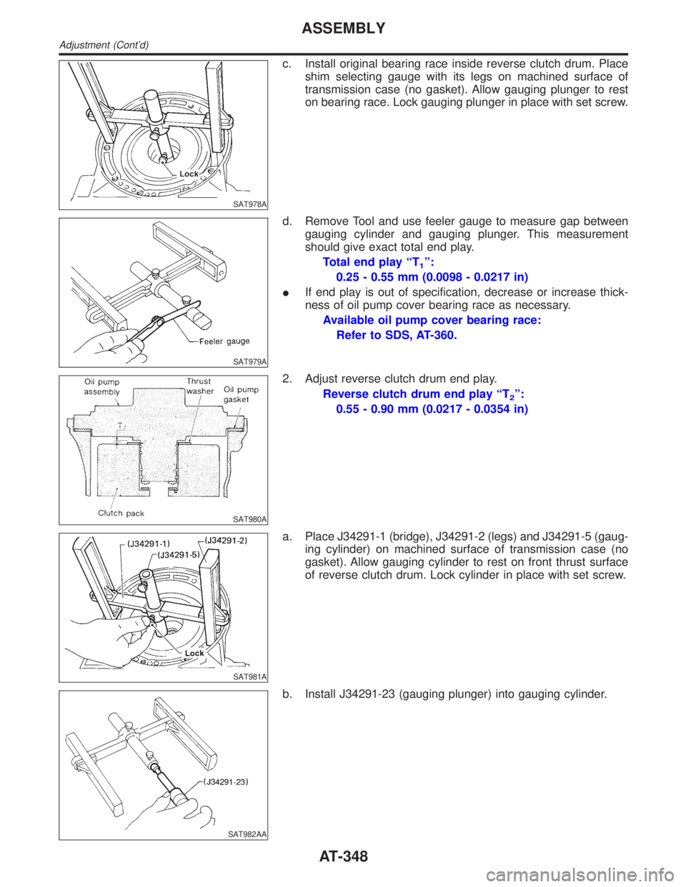
c. Install original bearing race inside reverse clutch drum. Place
shim selecting gauge with its legs on machined surface of
transmission case (no gasket). Allow gauging plunger to rest
on bearing race. Lock gauging plunger in place with set screw.
SAT979A
d. Remove Tool and use feeler gauge to measure gap between
gauging cylinder and gauging plunger. This measurement
should give exact total end play.
Total end play ªT
1º:
0.25 - 0.55 mm (0.0098 - 0.0217 in)
IIf end play is out of specification, decrease or increase thick-
ness of oil pump cover bearing race as necessary.
Available oil pump cover bearing race:
Refer to SDS, AT-360.
SAT980A
2. Adjust reverse clutch drum end play.
Reverse clutch drum end play ªT
2º:
0.55 - 0.90 mm (0.0217 - 0.0354 in)
SAT981A
a. Place J34291-1 (bridge), J34291-2 (legs) and J34291-5 (gaug-
ing cylinder) on machined surface of transmission case (no
gasket). Allow gauging cylinder to rest on front thrust surface
of reverse clutch drum. Lock cylinder in place with set screw.
SAT982AA
b. Install J34291-23 (gauging plunger) into gauging cylinder.
ASSEMBLY
Adjustment (Cont'd)
AT-348
Page 354 of 2395

SAT983A
c. Install original thrust washer on oil pump. Place shim setting
gauge legs onto machined surface of oil pump assembly. Allow
gauging plunger to rest on thrust washer. Lock plunger in place
with set screw.
SAT984A
d. Use feeler gauge to measure gap between gauging plunger
and gauging cylinder. This measurement should give you exact
reverse clutch drum end play.
Reverse clutch drum end play ªT
2º:
0.55 - 0.90 mm (0.0217 - 0.0354 in)
IIf end play is out of specification, decrease or increase thick-
ness of oil pump thrust washer as necessary.
Available oil pump thrust washer:
Refer to SDS, AT-361.
SAT985A
Assembly (2)NBAT01571. Install brake band and band strut.
a. Install band strut on brake band.
IApply petroleum jelly to band strut.
SAT986A
b. Place brake band on periphery of reverse clutch drum, and
insert band strut into end of band servo piston stem.
SAT987A
c. Install anchor end bolt on transmission case. Then, tighten
anchor end bolt just enough so that reverse clutch drum (clutch
pack) will not tilt forward.
GI
MA
EM
LC
EC
FE
TF
PD
AX
SU
BR
ST
RS
BT
HA
SC
EL
IDX
ASSEMBLY
Adjustment (Cont'd)
AT-349
Page 359 of 2395

SAT010B
j. Install torque converter clutch solenoid valve and A/T fluid tem-
perature sensor connectors.
SAT011B
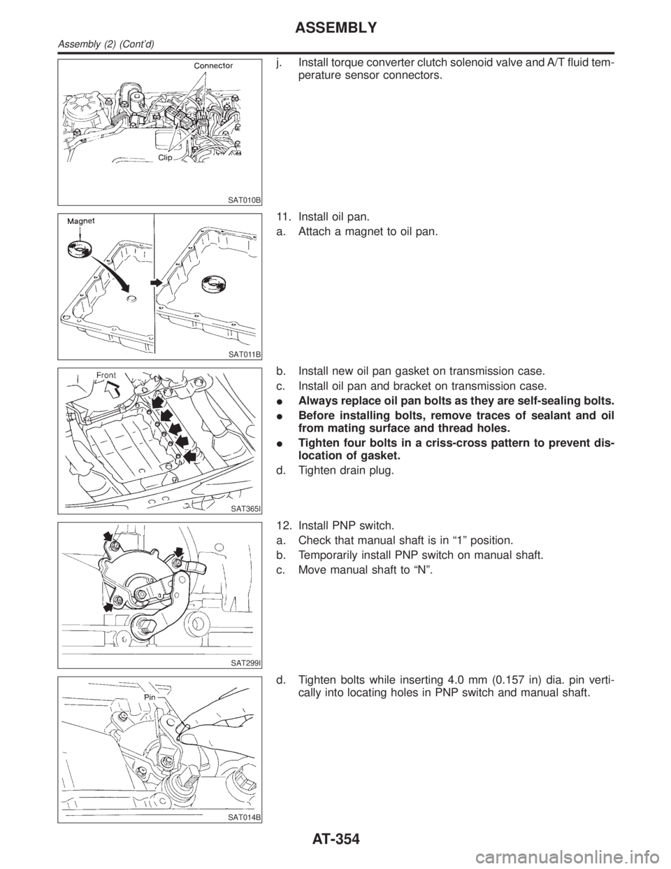
11. Install oil pan.
a. Attach a magnet to oil pan.
SAT365I
b. Install new oil pan gasket on transmission case.
c. Install oil pan and bracket on transmission case.
IAlways replace oil pan bolts as they are self-sealing bolts.
IBefore installing bolts, remove traces of sealant and oil
from mating surface and thread holes.
ITighten four bolts in a criss-cross pattern to prevent dis-
location of gasket.
d. Tighten drain plug.
SAT299I
12. Install PNP switch.
a. Check that manual shaft is in ª1º position.
b. Temporarily install PNP switch on manual shaft.
c. Move manual shaft to ªNº.
SAT014B
d. Tighten bolts while inserting 4.0 mm (0.157 in) dia. pin verti-
cally into locating holes in PNP switch and manual shaft.
ASSEMBLY
Assembly (2) (Cont'd)
AT-354
Page 362 of 2395

Return SpringsNBAT0165Unit: mm (in)
PartsItem
Part No.* Free length Outer diameter
Control valveUpper body1 Torque converter relief valve spring 31742-41X23 38.0 (1.496) 9.0 (0.354)
2 Pressure regulator valve spring 31742-41X24 44.02 (1.7331) 14.0 (0.551)
3 Pressure modifier valve spring 31742-41X19 31.95 (1.2579) 6.8 (0.268)
Ð Accumulator control valve spring Ð Ð Ð
4 Shuttle shift valve D spring 31762-41X01 25.0 (0.984) 7.0 (0.276)
5 4-2 sequence valve spring 31756-41X00 29.1 (1.146) 6.95 (0.2736)
6 Shift valve B spring 31762-41X01 25.0 (0.984) 7.0 (0.276)
7 4-2 relay valve spring 31756-41X00 29.1 (1.146) 6.95 (0.2736)
8 Shift valve A spring 31762-41X01 25.0 (0.984) 7.0 (0.276)
9 Overrun clutch control valve spring 31762-41X03 23.6 (0.929) 7.0 (0.276)
10 Overrun clutch reducing valve spring 31742-41X14 38.9 (1.531) 7.0 (0.276)
11 Shuttle shift valve S spring 31762-41X04 51.0 (2.008) 5.65 (0.2224)
12 Pilot valve spring 31742-41X13 25.7 (1.012) 9.0 (0.354)
13 Torque converter clutch control valve spring 31742-41X22 18.5 (0.728) 13.0 (0.512)
Lower body1 Modifier accumulator piston spring 31742-27X70 31.4 (1.236) 9.8 (0.386)
2 1st reducing valve spring 31756-60X00 20.5 (0.807) 7.0 (0.276)
3 3-2 timing valve spring 31742-41X06 23.0 (0.906) 6.7 (0.264)
4 Servo charger valve spring 31742-41X06 23.0 (0.906) 6.7 (0.264)
Reverse clutch Ð 31505-41X07 Ð Ð
High clutch10 pcs31521-41X03
(Assembly)24.2 (0.9528) 11.6 (0.457)
Forward clutch (Overrun clutch) 20 pcs31521-41X04
(Assembly)35.77 (1.4083) 9.7 (0.382)
Low & reverse brake 18 pcs31655-41X00
(Assembly)22.3 (0.878) 11.2 (0.441)
Band servoSpring A 31605-4AX03 45.6 (1.795) 34.3 (1.350)
Spring B 31605-41X01 29.7 (1.169) 27.6 (1.087)
AccumulatorAccumulator A 31605-41X02 43.0 (1.693) 18.0 (0.709)
Accumulator B 31605-41X14 47.6 (1.874) 26.5 (1.043)
Accumulator C 31605-41X09 45.0 (1.772) 29.3 (1.154)
Accumulator D 31605-41X06 58.4 (2.299) 17.3 (0.681)
GI
MA
EM
LC
EC
FE
TF
PD
AX
SU
BR
ST
RS
BT
HA
SC
EL
IDX
SERVICE DATA AND SPECIFICATIONS (SDS)
Return Springs
AT-357
Page 363 of 2395

Accumulator O-ringNBAT0166
AccumulatorDiameter mm (in)
ABC D
Small diameter end 29 (1.14) 32 (1.26) 45 (1.77) 29 (1.14)
Large diameter end 45 (1.77) 50 (1.97) 50 (1.97) 45 (1.77)
Clutches and BrakesNBAT0167REVERSE CLUTCHNBAT0167S01
Code number4EX16 4EX17
Number of drive plates2
Number of driven plates2
Thickness of drive plate mm (in)Standard 1.90 - 2.05 (0.0748 - 0.0807)
Wear limit 1.80 (0.0709)
Clearance mm (in)Standard 0.5 - 0.8 (0.020 - 0.031)
Allowable limit 1.2 (0.047)
Thickness of retaining plateThickness mm (in) Part number*
4.6 (0.181)
4.8 (0.189)
5.0 (0.197)
5.2 (0.205)
5.4 (0.213)31537-42X20
31537-42X21
31537-42X22
31537-42X23
31537-42X24
HIGH CLUTCHNBAT0167S02
Code number4EX16 4EX17
Number of drive plates5
Number of driven plates6
Thickness of drive plate mm (in)Standard 1.52 - 1.67 (0.0598 - 0.0657)
Wear limit 1.40 (0.0551)
Clearance mm (in)Standard 1.8 - 2.2 (0.071 - 0.087)
Allowable limit 3.2 (0.126)
Thickness of retaining plateThickness mm (in) Part number*
4.0 (0.157)
4.2 (0.165)
4.4 (0.173)
4.6 (0.181)
4.8 (0.189)
5.0 (0.197)31537-41X63
31537-41X64
31537-41X65
31537-41X66
31537-41X67
31537-41X68
SERVICE DATA AND SPECIFICATIONS (SDS)
Accumulator O-ring
AT-358
Page 364 of 2395

FORWARD CLUTCHNBAT0167S03
Code number 4EX16 4EX17
Number of drive plates 7 8
Number of driven plates 7 8
Thickness of drive
plate mm (in)Standard 1.52 - 1.67 (0.0598 - 0.0657)
Wear limit 1.40 (0.0551)
Clearance mm (in)Standard 0.35 - 0.75 (0.0138 - 0.0295)
Allowable limit 2.15 (0.0846) 2.35 (0.0925)
Thickness of retaining plateThickness mm (in) Part number* Thickness mm (in) Part number*
4.6 (0.181)
4.8 (0.189)
5.0 (0.197)
5.2 (0.205)
5.4 (0.213)
5.6 (0.220)31537-42X13
31537-42X14
31537-42X15
31537-4AX00
31537-4AX01
31537-4AX024.2 (0.165)
4.4 (0.173)
4.6 (0.181)
4.8 (0.189)
5.0 (0.197)
5.2 (0.205)
5.4 (0.213)31537-42X11
31537-42X12
31537-42X13
31537-42X14
31537-42X15
31537-4AX00
31537-4AX01
OVERRUN CLUTCHNBAT0167S04
Code number4EX16 4EX17
Number of drive plates3
Number of driven plates5
Thickness of drive plate mm (in)Standard 1.90 - 2.05 (0.0748 - 0.0807)
Wear limit 1.80 (0.0709)
Clearance mm (in)Standard 1.0 - 1.4 (0.039 - 0.055)
Allowable limit 2.0 (0.079)
Thickness of retaining plateThickness mm (in) Part number*
4.2 (0.165)
4.4 (0.173)
4.6 (0.181)
4.8 (0.189)
5.0 (0.197)31537-41X80
31537-41X81
31537-41X82
31537-41X83
31537-41X84
GI
MA
EM
LC
EC
FE
TF
PD
AX
SU
BR
ST
RS
BT
HA
SC
EL
IDX
SERVICE DATA AND SPECIFICATIONS (SDS)
Clutches and Brakes (Cont'd)
AT-359
Page 365 of 2395

LOW & REVERSE BRAKENBAT0167S05
Code number4EX16 4EX17
Number of drive plates8
Number of driven plates8
Thickness of drive plate mm (in)Standard 1.90 - 2.05 (0.0748 - 0.0807) 1.52 - 1.67 (0.0598 - 0.0657)
Wear limit 1.40 (0.0551)
Clearance mm (in)Standard 0.8 - 1.1 (0.031 - 0.043)
Allowable limit 2.7 (0.106)
Thickness of retaining plateThickness mm (in) Part number*
7.6 (0.299)
7.8 (0.307)
8.0 (0.315)
8.2 (0.323)
8.4 (0.331)
8.6 (0.339)
8.8 (0.346)
9.0 (0.354)
9.2 (0.362)
9.4 (0.370)
9.6 (0.378)31667-41X07
31667-41X08
31667-41X00
31667-41X01
31667-41X02
31667-41X03
31667-41X04
31667-41X05
31667-41X06
31667-41X09
31667-41X10
BRAKE BANDNBAT0167S06
Anchor end bolt nut tightening torque 40 - 51 N´m (4.1 - 5.2 kg-m, 30 - 38 ft-lb)
Anchor end bolt tightening torque4 - 6 N´m (0.4 - 0.6 kg-m, 35 - 52 in-lb)
Number of returning revolution for anchor end bolt 2.5
Oil Pump and Low One-way ClutchNBAT0168Unit: mm (in)
Oil pump clearanceCam ring Ð oil pump housing Standard 0.01 - 0.024 (0.0004 - 0.0009)
Rotor, vanes and control piston Ð oil
pump housingStandard 0.03 - 0.044 (0.0012 - 0.0017)
Seal ring clearanceStandard 0.10 - 0.25 (0.0039 - 0.0098)
Allowable limit 0.25 (0.0098)
Total End PlayNBAT0169
Total end play ªT1º 0.25 - 0.55 mm (0.0098 - 0.0217 in)
Thickness of oil pump cover bearing raceThickness mm (in) Part number*
0.8 (0.031)
1.0 (0.039)
1.2 (0.047)
1.4 (0.055)
1.6 (0.063)
1.8 (0.071)
2.0 (0.079)31435-41X01
31435-41X02
31435-41X03
31435-41X04
31435-41X05
31435-41X06
31435-41X07
SERVICE DATA AND SPECIFICATIONS (SDS)
Clutches and Brakes (Cont'd)
AT-360
Page 366 of 2395

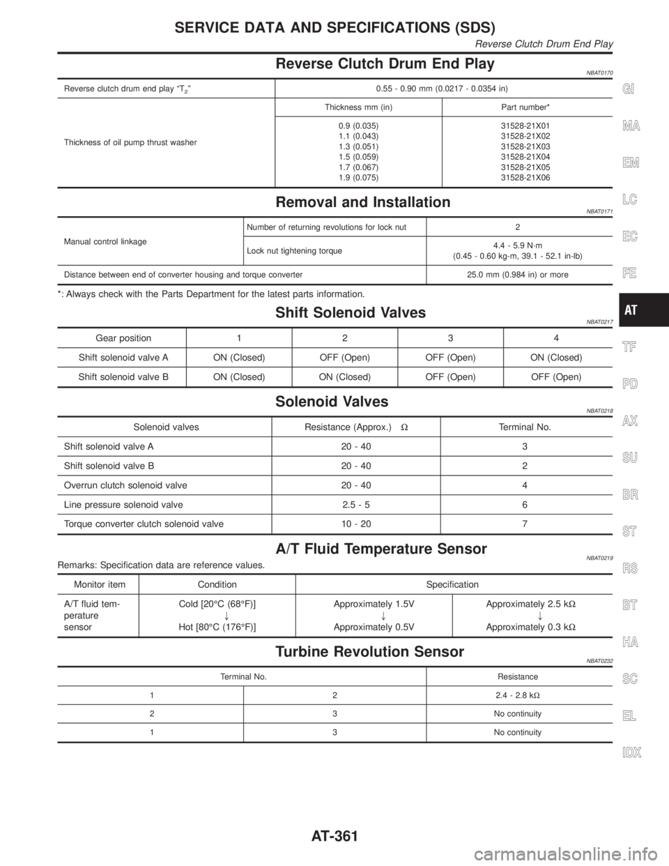
Reverse Clutch Drum End PlayNBAT0170
Reverse clutch drum end play ªT2º 0.55 - 0.90 mm (0.0217 - 0.0354 in)
Thickness of oil pump thrust washerThickness mm (in) Part number*
0.9 (0.035)
1.1 (0.043)
1.3 (0.051)
1.5 (0.059)
1.7 (0.067)
1.9 (0.075)31528-21X01
31528-21X02
31528-21X03
31528-21X04
31528-21X05
31528-21X06
Removal and InstallationNBAT0171
Manual control linkageNumber of returning revolutions for lock nut 2
Lock nut tightening torque4.4 - 5.9 N´m
(0.45 - 0.60 kg-m, 39.1 - 52.1 in-lb)
Distance between end of converter housing and torque converter 25.0 mm (0.984 in) or more
*: Always check with the Parts Department for the latest parts information.
Shift Solenoid ValvesNBAT0217
Gear position1234
Shift solenoid valve A ON (Closed) OFF (Open) OFF (Open) ON (Closed)
Shift solenoid valve B ON (Closed) ON (Closed) OFF (Open) OFF (Open)
Solenoid ValvesNBAT0218
Solenoid valves Resistance (Approx.)WTerminal No.
Shift solenoid valve A 20 - 40 3
Shift solenoid valve B 20 - 40 2
Overrun clutch solenoid valve 20 - 40 4
Line pressure solenoid valve 2.5 - 5 6
Torque converter clutch solenoid valve 10 - 20 7
A/T Fluid Temperature SensorNBAT0219Remarks: Specification data are reference values.
Monitor item Condition Specification
A/T fluid tem-
perature
sensorCold [20ÉC (68ÉF)]
"
Hot [80ÉC (176ÉF)]Approximately 1.5V
"
Approximately 0.5VApproximately 2.5 kW
"
Approximately 0.3 kW
Turbine Revolution SensorNBAT0232
Terminal No. Resistance
1 2 2.4 - 2.8 kW
2 3 No continuity
1 3 No continuity
GI
MA
EM
LC
EC
FE
TF
PD
AX
SU
BR
ST
RS
BT
HA
SC
EL
IDX
SERVICE DATA AND SPECIFICATIONS (SDS)
Reverse Clutch Drum End Play
AT-361
Page 461 of 2395

2 CHECK SYMPTOM
1. Apply brake.
2. Start engine.
Does the symptom appear only when engine is started?
Ye s©Carry out self-diagnosis. Refer to BR-41, 44.
No©Go to ª3. CHECK WARNING LAMP INDICATIONº in ª2. Unexpected Pedal Actionº,
BR-70.
NOTE:
ABS may operate and cause vibration under any of the following
conditions.
IApplying brake gradually when shifting or operating clutch.
ILow friction (slippery) road.
IHigh speed cornering.
IDriving over bumps and pot holes.
IEngine speed is over 5,000 rpm with vehicle stopped.
6. Warning Lamp Does Not Come On When
Ignition Switch Is Turned On
NBBR0112
1 INSPECTION START
Warning lamp circuit inspection
SBR673E
©GO TO 2.
2 CHECK FUSE
Check 10A fuse No. 8. For fuse layout, refer to EL-16, ªPOWER SUPPLY ROUTINGº.
Is fuse OK?
Ye s©GO TO 3.
No©Replace fuse.
TROUBLE DIAGNOSES FOR SYMPTOMSABS
5. Pedal Vibration and Noise (Cont'd)
BR-72
Page 478 of 2395

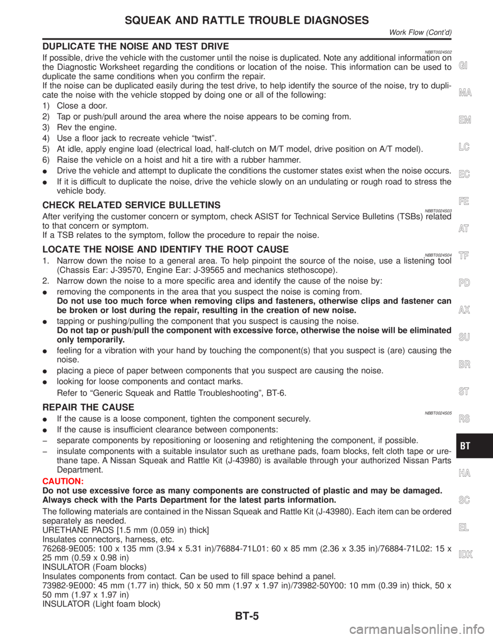
DUPLICATE THE NOISE AND TEST DRIVENBBT0024S02If possible, drive the vehicle with the customer until the noise is duplicated. Note any additional information on
the Diagnostic Worksheet regarding the conditions or location of the noise. This information can be used to
duplicate the same conditions when you confirm the repair.
If the noise can be duplicated easily during the test drive, to help identify the source of the noise, try to dupli-
cate the noise with the vehicle stopped by doing one or all of the following:
1) Close a door.
2) Tap or push/pull around the area where the noise appears to be coming from.
3) Rev the engine.
4) Use a floor jack to recreate vehicle ªtwistº.
5) At idle, apply engine load (electrical load, half-clutch on M/T model, drive position on A/T model).
6) Raise the vehicle on a hoist and hit a tire with a rubber hammer.
IDrive the vehicle and attempt to duplicate the conditions the customer states exist when the noise occurs.
IIf it is difficult to duplicate the noise, drive the vehicle slowly on an undulating or rough road to stress the
vehicle body.
CHECK RELATED SERVICE BULLETINSNBBT0024S03After verifying the customer concern or symptom, check ASIST for Technical Service Bulletins (TSBs) related
to that concern or symptom.
If a TSB relates to the symptom, follow the procedure to repair the noise.
LOCATE THE NOISE AND IDENTIFY THE ROOT CAUSENBBT0024S041. Narrow down the noise to a general area. To help pinpoint the source of the noise, use a listening tool
(Chassis Ear: J-39570, Engine Ear: J-39565 and mechanics stethoscope).
2. Narrow down the noise to a more specific area and identify the cause of the noise by:
Iremoving the components in the area that you suspect the noise is coming from.
Do not use too much force when removing clips and fasteners, otherwise clips and fastener can
be broken or lost during the repair, resulting in the creation of new noise.
Itapping or pushing/pulling the component that you suspect is causing the noise.
Do not tap or push/pull the component with excessive force, otherwise the noise will be eliminated
only temporarily.
Ifeeling for a vibration with your hand by touching the component(s) that you suspect is (are) causing the
noise.
Iplacing a piece of paper between components that you suspect are causing the noise.
Ilooking for loose components and contact marks.
Refer to ªGeneric Squeak and Rattle Troubleshootingº, BT-6.
REPAIR THE CAUSENBBT0024S05IIf the cause is a loose component, tighten the component securely.
IIf the cause is insufficient clearance between components:
þ separate components by repositioning or loosening and retightening the component, if possible.
þ insulate components with a suitable insulator such as urethane pads, foam blocks, felt cloth tape or ure-
thane tape. A Nissan Squeak and Rattle Kit (J-43980) is available through your authorized Nissan Parts
Department.
CAUTION:
Do not use excessive force as many components are constructed of plastic and may be damaged.
Always check with the Parts Department for the latest parts information.
The following materials are contained in the Nissan Squeak and Rattle Kit (J-43980). Each item can be ordered
separately as needed.
URETHANE PADS [1.5 mm (0.059 in) thick]
Insulates connectors, harness, etc.
76268-9E005: 100 x 135 mm (3.94 x 5.31 in)/76884-71L01: 60 x 85 mm (2.36 x 3.35 in)/76884-71L02: 15 x
25 mm (0.59 x 0.98 in)
INSULATOR (Foam blocks)
Insulates components from contact. Can be used to fill space behind a panel.
73982-9E000: 45 mm (1.77 in) thick, 50 x 50 mm (1.97 x 1.97 in)/73982-50Y00: 10 mm (0.39 in) thick, 50 x
50 mm (1.97 x 1.97 in)
INSULATOR (Light foam block)
GI
MA
EM
LC
EC
FE
AT
TF
PD
AX
SU
BR
ST
RS
HA
SC
EL
IDX
SQUEAK AND RATTLE TROUBLE DIAGNOSES
Work Flow (Cont'd)
BT-5