Battery INFINITI QX4 2001 Factory Service Manual
[x] Cancel search | Manufacturer: INFINITI, Model Year: 2001, Model line: QX4, Model: INFINITI QX4 2001Pages: 2395, PDF Size: 43.2 MB
Page 1151 of 2395

SEF375Z
Component DescriptionNBEC0383The fuel injector is a small, precise solenoid valve. When the ECM
supplies a ground to the injector circuit, the coil in the injector is
energized. The energized coil pulls the needle valve back and
allows fuel to flow through the injector into the intake manifold. The
amount of fuel injected depends upon the injection pulse duration.
Pulse duration is the length of time the injector remains open. The
ECM controls the injection pulse duration based on engine fuel
needs.
CONSULT-II Reference Value in Data Monitor
Mode
NBEC0384Specification data are reference values.
MONITOR ITEM CONDITION SPECIFICATION
INJ PULSE-B2
INJ PULSE-B1IEngine: After warming up
IAir conditioner switch: ªOFFº
IShift lever: ªNº
INo-loadIdle 2.4 - 3.2 msec
2,000 rpm 1.9 - 2.8 msec
B/FUEL SCHDL dittoIdle 2.0 - 3.2 msec
2,000 rpm 1.4 - 2.6 msec
ECM Terminals and Reference ValueNBEC0685Specification data are reference values and are measured between each terminal and ground.
CAUTION:
Do not use ECM ground terminals when measuring input/output voltage. Doing so may result in dam-
age to the ECM's transistor. Use a ground other than ECM terminals, such as the ground.
TERMI-
NAL
NO.WIRE
COLORITEM CONDITION DATA (DC Voltage)
101
102
103
104
105
107R/B
L/W
R/W
PU/R
R/Y
R/LInjector No. 1
Injector No. 5
Injector No. 2
Injector No. 6
Injector No. 3
Injector No. 4[Engine is running]
IIdle speedBATTERY VOLTAGE
(11 - 14V)
INJECTOR
Component Description
EC-616
Page 1160 of 2395

System DescriptionNBEC0392
Sensor Input Signal to ECMECM func-
tionActuator
Crankshaft position sensor (POS) Engine speed (POS signal)
Fuel pump
controlFuel pump relay Crankshaft position sensor (REF) Engine speed (REF signal)
Ignition switch Start signal
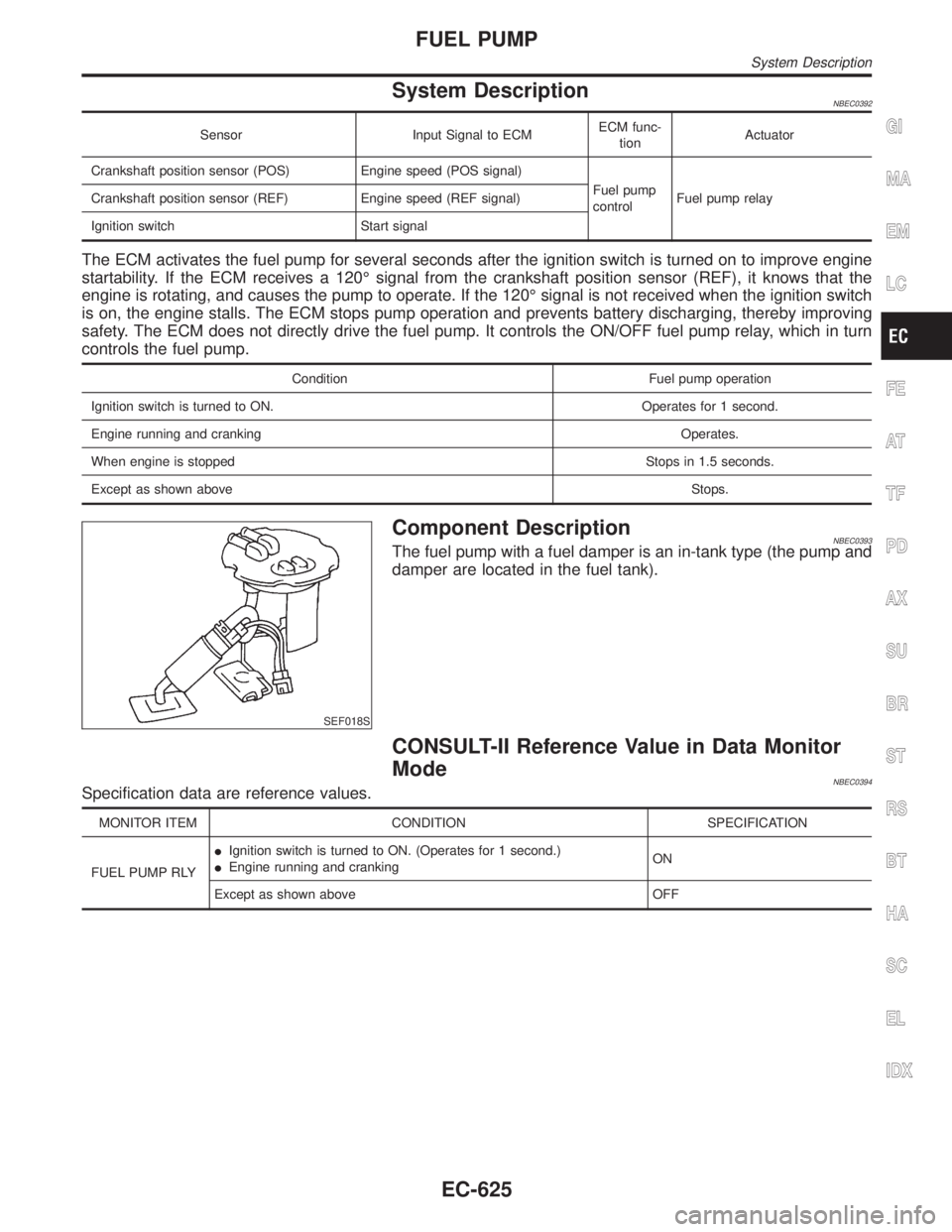
The ECM activates the fuel pump for several seconds after the ignition switch is turned on to improve engine
startability. If the ECM receives a 120É signal from the crankshaft position sensor (REF), it knows that the
engine is rotating, and causes the pump to operate. If the 120É signal is not received when the ignition switch
is on, the engine stalls. The ECM stops pump operation and prevents battery discharging, thereby improving
safety. The ECM does not directly drive the fuel pump. It controls the ON/OFF fuel pump relay, which in turn
controls the fuel pump.
Condition Fuel pump operation
Ignition switch is turned to ON. Operates for 1 second.
Engine running and cranking Operates.
When engine is stopped Stops in 1.5 seconds.
Except as shown aboveStops.
SEF018S
Component DescriptionNBEC0393The fuel pump with a fuel damper is an in-tank type (the pump and
damper are located in the fuel tank).
CONSULT-II Reference Value in Data Monitor
Mode
NBEC0394Specification data are reference values.
MONITOR ITEM CONDITION SPECIFICATION
FUEL PUMP RLYIIgnition switch is turned to ON. (Operates for 1 second.)
IEngine running and crankingON
Except as shown above OFF
GI
MA
EM
LC
FE
AT
TF
PD
AX
SU
BR
ST
RS
BT
HA
SC
EL
IDX
FUEL PUMP
System Description
EC-625
Page 1161 of 2395

ECM Terminals and Reference Value=NBEC0686Specification data are reference values and are measured between each terminal and ground.
CAUTION:
Do not use ECM ground terminals when measuring input/output voltage. Doing so may result in dam-
age to the ECM's transistor. Use a ground other than ECM terminals, such as the ground.
TERMI-
NAL
NO.WIRE
COLORITEM CONDITION DATA (DC Voltage)
28 R/L Fuel pump relay[Ignition switch ªONº]
IFor 1 second after turning ignition switch ªONº
[Engine is running]0 - 1.5V
[Ignition switch ªONº]
I1 second passed after turning ignition switch
ªONº.BATTERY VOLTAGE
(11 - 14V)
FUEL PUMP
ECM Terminals and Reference Value
EC-626
Page 1178 of 2395

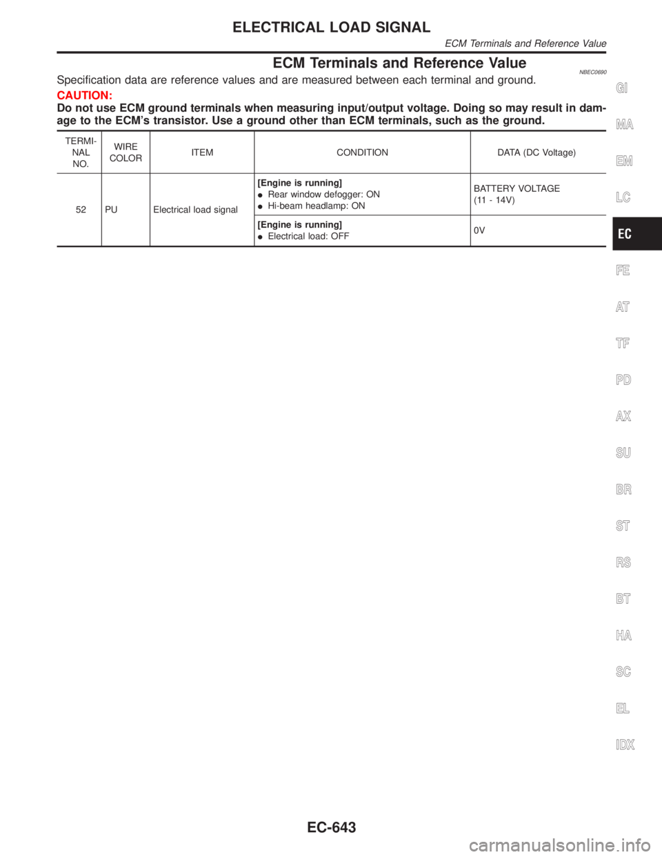
ECM Terminals and Reference ValueNBEC0690Specification data are reference values and are measured between each terminal and ground.
CAUTION:
Do not use ECM ground terminals when measuring input/output voltage. Doing so may result in dam-
age to the ECM's transistor. Use a ground other than ECM terminals, such as the ground.
TERMI-
NAL
NO.WIRE
COLORITEM CONDITION DATA (DC Voltage)
52 PU Electrical load signal[Engine is running]
IRear window defogger: ON
IHi-beam headlamp: ONBATTERY VOLTAGE
(11 - 14V)
[Engine is running]
IElectrical load: OFF0V
GI
MA
EM
LC
FE
AT
TF
PD
AX
SU
BR
ST
RS
BT
HA
SC
EL
IDX
ELECTRICAL LOAD SIGNAL
ECM Terminals and Reference Value
EC-643
Page 1184 of 2395

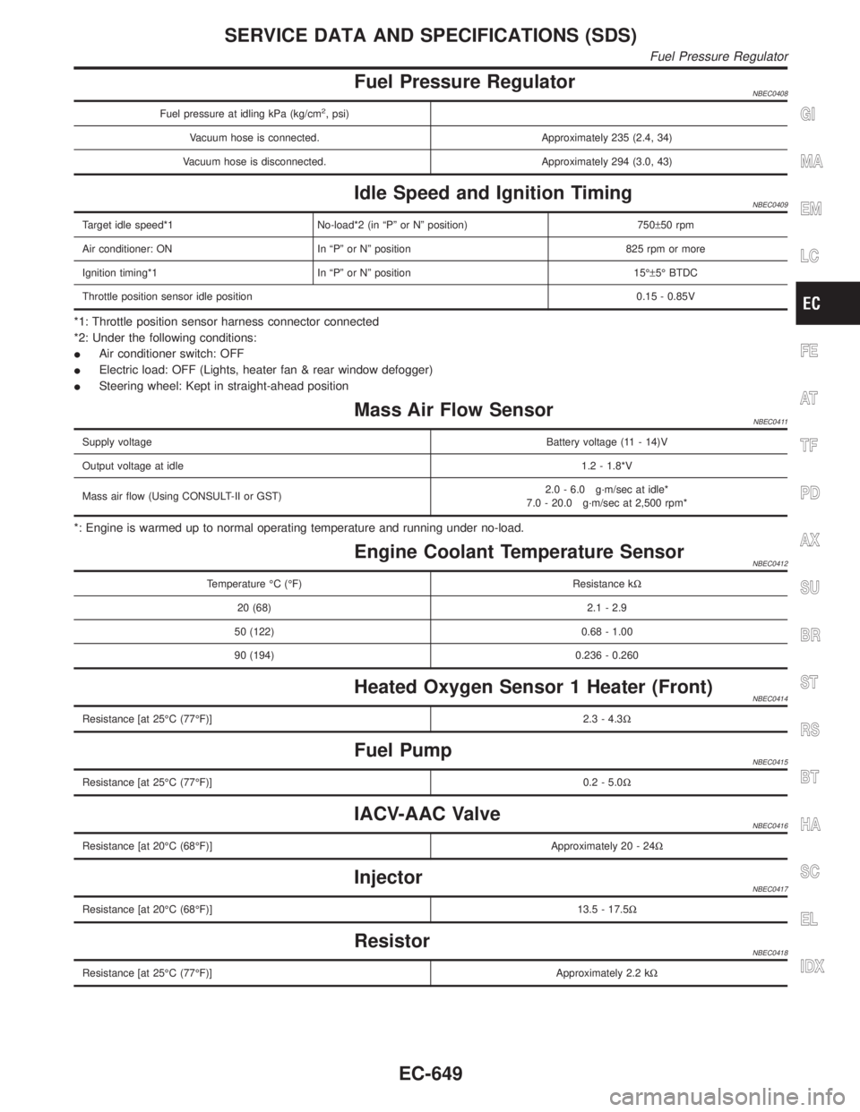
Fuel Pressure RegulatorNBEC0408
Fuel pressure at idling kPa (kg/cm2, psi)
Vacuum hose is connected. Approximately 235 (2.4, 34)
Vacuum hose is disconnected. Approximately 294 (3.0, 43)
Idle Speed and Ignition TimingNBEC0409
Target idle speed*1 No-load*2 (in ªPº or Nº position) 750±50 rpm
Air conditioner: ON In ªPº or Nº position 825 rpm or more
Ignition timing*1 In ªPº or Nº position 15ɱ5É BTDC
Throttle position sensor idle position0.15 - 0.85V
*1: Throttle position sensor harness connector connected
*2: Under the following conditions:
IAir conditioner switch: OFF
IElectric load: OFF (Lights, heater fan & rear window defogger)
ISteering wheel: Kept in straight-ahead position
Mass Air Flow SensorNBEC0411
Supply voltageBattery voltage (11 - 14)V
Output voltage at idle1.2 - 1.8*V
Mass air flow (Using CONSULT-II or GST)2.0 - 6.0 g´m/sec at idle*
7.0 - 20.0 g´m/sec at 2,500 rpm*
*: Engine is warmed up to normal operating temperature and running under no-load.
Engine Coolant Temperature SensorNBEC0412
Temperature ÉC (ÉF) Resistance kW
20 (68) 2.1 - 2.9
50 (122) 0.68 - 1.00
90 (194) 0.236 - 0.260
Heated Oxygen Sensor 1 Heater (Front)NBEC0414
Resistance [at 25ÉC (77ÉF)]2.3 - 4.3W
Fuel PumpNBEC0415
Resistance [at 25ÉC (77ÉF)]0.2 - 5.0W
IACV-AAC ValveNBEC0416
Resistance [at 20ÉC (68ÉF)]Approximately 20 - 24W
InjectorNBEC0417
Resistance [at 20ÉC (68ÉF)]13.5 - 17.5W
ResistorNBEC0418
Resistance [at 25ÉC (77ÉF)]Approximately 2.2 kW
GI
MA
EM
LC
FE
AT
TF
PD
AX
SU
BR
ST
RS
BT
HA
SC
EL
IDX
SERVICE DATA AND SPECIFICATIONS (SDS)
Fuel Pressure Regulator
EC-649
Page 1188 of 2395

Schematic ................................................................255
Wiring Diagram - D/LOCK -.....................................256
Trouble Diagnoses...................................................261
MULTI-REMOTE CONTROL SYSTEM.......................270
Component Parts and Harness Connector
Location ...................................................................270
System Description ..................................................270
Schematic ................................................................273
Wiring Diagram - MULTI - .......................................274
Trouble Diagnoses...................................................277
ID Code Entry Procedure ........................................289
Remote Controller Battery Replacement.................293
THEFT WARNING SYSTEM.......................................294
Component Parts and Harness Connector
Location ...................................................................294
System Description ..................................................295
Schematic ................................................................298
Wiring Diagram - THEFT -.......................................300
Trouble Diagnoses...................................................306
SMART ENTRANCE CONTROL UNIT.......................319
Description ...............................................................319
Schematic ................................................................322
Smart Entrance Control Unit Inspection Table ........324
INTEGRATED HOMELINK TRANSMITTER...............325
Wiring Diagram - TRNSMT - ...................................325
Trouble Diagnoses...................................................326
IVIS (INFINITI VEHICLE IMMOBILIZER SYSTEM -
NATS)...........................................................................328
Component Parts and Harness Connetor
Location ...................................................................328
System Description ..................................................329
System Composition ................................................329
Wiring Diagram - NATS -.........................................330
CONSULT-II .............................................................331
Trouble Diagnoses...................................................334
How to Replace IVIS (NATS) IMMU .......................347
INFINITI COMMUNICATOR (IVCS)............................348
Precaution ................................................................348
Communicator Response Center Telephone
Number for Technicians ...........................................348
Component Parts and Harness Connector
Location ...................................................................349System Description ..................................................350
Schematic ................................................................358
Wiring Diagram - IVCS -..........................................359
CONSULT-II .............................................................363
Trouble Diagnoses...................................................368
Trouble Diagnoses for Intermittent Incident ............377
Demonstration Mode ...............................................379
System Setting (When IVCS Unit is Replaced) ......381
NAVIGATION SYSTEM...............................................385
Component Parts Location ......................................385
System Description ..................................................386
Schematic ................................................................393
Wiring Diagram - NAVI - ..........................................394
Self-diagnosis Mode ................................................397
Confirmation/Adjustment Mode ...............................400
Setting Mode............................................................410
Trouble diagnoses ...................................................417
This Condition is Not Abnormal ...............................423
Program Loading .....................................................432
Initialization ..............................................................433
ELECTRICAL UNITS LOCATION...............................436
Engine Compartment ...............................................436
Passenger Compartment .........................................438
HARNESS LAYOUT....................................................440
How to Read Harness Layout .................................440
Outline......................................................................441
Main Harness...........................................................442
Engine Room Harness ............................................444
Engine Control Harness ..........................................446
Body Harness LH ....................................................448
Body Harness RH ....................................................449
Back Door Harness .................................................450
Engine and Transmission Harness..........................451
Room Lamp Harness...............................................452
Air Bag Harness ......................................................453
Front Door Harness .................................................454
Rear Door Harness..................................................455
BULB SPECIFICATIONS............................................456
Headlamp.................................................................456
Exterior Lamp ..........................................................456
Interior Lamp............................................................456
WIRING DIAGRAM CODES (CELL CODES).............457GI
MA
EM
LC
EC
FE
AT
TF
PD
AX
SU
BR
ST
RS
BT
HA
SC
IDX
CONTENTS(Cont'd)
EL-3
Page 1195 of 2395

Wiring Diagram Ð POWER ÐNBEL0006BATTERY POWER SUPPLY Ð IGNITION SW. IN ANY POSITIONNBEL0006S01
MEL755L
POWER SUPPLY ROUTING
Wiring Diagram Ð POWER Ð
EL-10
Page 1216 of 2395

Component Parts and Harness Connector
Location
NBEL0159
SEL460X
System DescriptionNBEL0188The headlamp operation is controlled by the lighting switch which is built into the combination switch and
headlamp battery saver control unit. And the headlamp battery saver system is controlled by the headlamp
battery saver control unit and smart entrance control unit.
OUTLINENBEL0188S01Power is supplied at all times
Ito headlamp LH relay terminals 1 and 3
Ithrough 15A fuse (No. 60, located in the fuse and fusible link box), and
Ito headlamp LH relay terminal 6
Ithrough 20A fuse (No. 32, located in the fuse and fusible link box), and
Ito headlamp RH relay terminals 1 and 3
Ithrough 15A fuse (No. 59, located in the fuse and fusible link box), and
Ito headlamp RH relay terminal 6
Ithrough 20A fuse (No. 31, located in the fuse and fusible link box), and
Ito headlamp battery saver control unit terminal 7, and
Ito smart entrance control unit terminal 10
Ithrough 7.5A fuse [No. 24, located in the fuse block (J/B)].
When the ignition switch is in the ON or START position, power is supplied
Ito headlamp battery saver control unit terminal 1
Ithrough 10A fuse [No. 16, located in the fuse block (J/B)], and
Ito headlamp battery saver control unit terminal 10,
Ito auto light control unit terminal 1 and
Ito smart entrance control unit terminal 33
Ithrough 7.5A fuse [No. 11, located in the fuse block (J/B)].
GI
MA
EM
LC
EC
FE
AT
TF
PD
AX
SU
BR
ST
RS
BT
HA
SC
IDX
HEADLAMP (FOR USA) Ð XENON TYPE Ð
Component Parts and Harness Connector Location
EL-31
Page 1217 of 2395
![INFINITI QX4 2001 Factory Service Manual When the ignition switch is in the ACC or ON position, power is supplied
Ito auto light control unit terminal 2
Ithrough 10A fuse [No. 9, located in the fuse block (J/B)]
Ground is supplied
Ito headla INFINITI QX4 2001 Factory Service Manual When the ignition switch is in the ACC or ON position, power is supplied
Ito auto light control unit terminal 2
Ithrough 10A fuse [No. 9, located in the fuse block (J/B)]
Ground is supplied
Ito headla](/img/42/57027/w960_57027-1216.png)
When the ignition switch is in the ACC or ON position, power is supplied
Ito auto light control unit terminal 2
Ithrough 10A fuse [No. 9, located in the fuse block (J/B)]
Ground is supplied
Ito headlamp battery saver control unit terminals 4 and 11
Ithrough body grounds M77 and M111, and M4,M66 and M147
Ito auto light control unit terminal 5
Ithrough body grounds M4, M66 and M147.
Power Supply to Low Beam and High BeamNBEL0188S0101When lighting switch is in 2ND or PASS position, ground is supplied
Ito headlamp relay (LH and RH) terminal 2 from headlamp battery saver control unit terminals 2 and 8
Ithrough headlamp battery saver control unit terminals 3 and 9,
Ifrom lighting switch terminal 12.
Headlamp relays (LH and RH) are energized and then power is supplied to headlamps (LH and RH).
LOW BEAM OPERATIONNBEL0188S02When the lighting switch is turned to the 2ND position and placed in LOW (ªBº) position, power is supplied
Ifrom terminal 7 of each headlamp relay
Ito terminal 3 of each headlamp
Ground is supplied
Ito terminal 4 of each headlamp
Ithrough body grounds E13 and E41.
With power and ground supplied, the headlamp(s) will illuminate.
HIGH BEAM OPERATION/FLASH-TO-PASS OPERATIONNBEL0188S03When the lighting switch is turned to the 2ND position and placed in HIGH (ªAº) position or PASS (ªCº) position,
power is supplied
Ifrom terminal 5 of headlamp LH relay
Ito terminal 1 of headlamp LH, and
Ito combination meter terminal 26 for the HIGH BEAM indicator
Ifrom terminal 5 of headlamp RH relay
Ito terminal 1 of headlamp RH.
Ground is supplied
Ito headlamp LH terminal 2
Ito combination meter terminal 27 for the HIGH BEAM indicator
Ithrough lighting switch terminals 6 and 5
Ithrough body grounds E13 and E41, and
Ito headlamp RH terminal 2
Ithrough lighting switch terminals 9 and 8
Ithrough body grounds E13 and E41.
With power and ground supplied, the high beams and the high beam indicator illuminate.
BATTERY SAVER CONTROLNBEL0188S04When the ignition switch is turned from ON (or START) to OFF (or ACC) positions while headlamps illuminate,
the RAP signal is supplied to terminal 10 of the headlamp battery saver control unit from smart entrance con-
trol unit terminal 5.
After counting 45 seconds by the RAP signal from the smart entrance control unit to headlamp battery saver
control unit, the ground supply to terminal 2 of the headlamp LH and RH relay from headlamp battery saver
control unit terminals 2 and 8 is terminated.
Then the headlamps are turned off.
The headlamps are turned off when driver or passenger side door is opened even if 45 seconds have not
passed after ignition switch is turned from ON (or START) to OFF (or ACC) positions while headlamps are
illuminated.
When the lighting switch is turned from OFF to 2ND after headlamps are turned to off by the battery saver
control, ground is supplied
HEADLAMP (FOR USA) Ð XENON TYPE Ð
System Description (Cont'd)
EL-32
Page 1218 of 2395

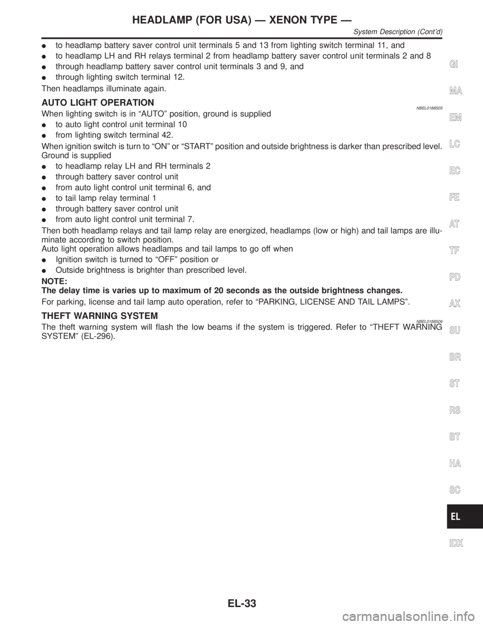
Ito headlamp battery saver control unit terminals 5 and 13 from lighting switch terminal 11, and
Ito headlamp LH and RH relays terminal 2 from headlamp battery saver control unit terminals 2 and 8
Ithrough headlamp battery saver control unit terminals 3 and 9, and
Ithrough lighting switch terminal 12.
Then headlamps illuminate again.
AUTO LIGHT OPERATIONNBEL0188S05When lighting switch is in ªAUTOº position, ground is supplied
Ito auto light control unit terminal 10
Ifrom lighting switch terminal 42.
When ignition switch is turn to ªONº or ªSTARTº position and outside brightness is darker than prescribed level.
Ground is supplied
Ito headlamp relay LH and RH terminals 2
Ithrough battery saver control unit
Ifrom auto light control unit terminal 6, and
Ito tail lamp relay terminal 1
Ithrough battery saver control unit
Ifrom auto light control unit terminal 7.
Then both headlamp relays and tail lamp relay are energized, headlamps (low or high) and tail lamps are illu-
minate according to switch position.
Auto light operation allows headlamps and tail lamps to go off when
IIgnition switch is turned to ªOFFº position or
IOutside brightness is brighter than prescribed level.
NOTE:
The delay time is varies up to maximum of 20 seconds as the outside brightness changes.
For parking, license and tail lamp auto operation, refer to ªPARKING, LICENSE AND TAIL LAMPSº.
THEFT WARNING SYSTEMNBEL0188S06The theft warning system will flash the low beams if the system is triggered. Refer to ªTHEFT WARNING
SYSTEMº (EL-296).
GI
MA
EM
LC
EC
FE
AT
TF
PD
AX
SU
BR
ST
RS
BT
HA
SC
IDX
HEADLAMP (FOR USA) Ð XENON TYPE Ð
System Description (Cont'd)
EL-33