Battery INFINITI QX4 2001 Factory Service Manual
[x] Cancel search | Manufacturer: INFINITI, Model Year: 2001, Model line: QX4, Model: INFINITI QX4 2001Pages: 2395, PDF Size: 43.2 MB
Page 975 of 2395

System DescriptionNBEC0264This circuit line (LAN) is used to control the smooth shifting up and down of A/T during the hard acceleration/
deceleration.
Pulse signals are exchanged between ECM and TCM (Transmission Control Module).
Be sure to erase the malfunction information such as DTC not only in TCM but also ECM after the A/T
related repair.
ECM Terminals and Reference ValueNBEC0672Specification data are reference values and are measured between each terminal and ground.
CAUTION:
Do not use ECM ground terminals when measuring input/output voltage. Doing so may result in dam-
age to the ECM's transistor. Use a ground other than ECM terminals, such as the ground.
TERMI-
NAL
NO.WIRE
COLORITEM CONDITION DATA (DC Voltage)
114 G/RCommunication line
(LAN)[Engine is running]
IIdle speedApproximately 2V
On Board Diagnosis LogicNBEC0266Malfunction is detected when ECM receives incorrect voltage from
TCM (Transmission Control Module) continuously.
Possible CauseNBEC0517IHarness or connectors
[The communication line circuit between ECM and TCM
(Transmission Control Module) is open or shorted.]
ITCM
IDead (Weak) battery
SEF058Y
DTC Confirmation ProcedureNBEC0267NOTE:
If ªDTC Confirmation Procedureº has been previously conducted,
always turn ignition switch ªOFFº and wait at least 10 seconds
before conducting the next test.
TESTING CONDITION:
Before performing the following procedure, confirm that bat-
tery voltage is more than 10.5V at idle.
WITH CONSULT-IINBEC0267S011) Turn ignition switch ªONº.
DTC P0600 A/T COMMUNICATION LINE
System Description
EC-440
Page 982 of 2395

ECM Terminals and Reference Value=NBEC0693Specification data are reference values, and are measured between each terminal and ground.
CAUTION:
Do not use ECM ground terminals when measuring voltage. Doing so may result in damage to the
ECM's transistor. Use a ground other than the ECM terminals, such as the ground.
TERMI-
NAL
NO.WIRE
COLORITEM CONDITION DATA (DC Voltage)
13 OR/BIntake valve timing
control solenoid valves
(RH)[Engine is running]
IWarm-up condition
IIdle speedBattery voltage
[Engine is running]
IWarm-up condition
IEngine speed is 2,000 rpm.7-8V
SEF350Z
15 P/LIntake valve timing
control solenoid valves
(LH)[Engine is running]
IWarm-up condition
IIdle speedBattery voltage
[Engine is running]
IWarm-up condition
IEngine speed is 2,000 rpm.7-8V
SEF350Z
79 Y/GIntake valve timing
control position sen-
sors (RH)[Engine is running]
IWarm-up condition
IIdle speedApproximately 0.5VSEF351Z
[Engine is running]
IWarm-up condition
IEngine speed is 2,000 rpm.Approximately 0.5V
SEF352Z
GI
MA
EM
LC
FE
AT
TF
PD
AX
SU
BR
ST
RS
BT
HA
SC
EL
IDX
DTC P1110 (RIGHT, -B1), P1135 (LEFT, -B2) INTAKE VALVE TIMING CONTROL
ECM Terminals and Reference Value
EC-447
Page 986 of 2395

SEF354Z
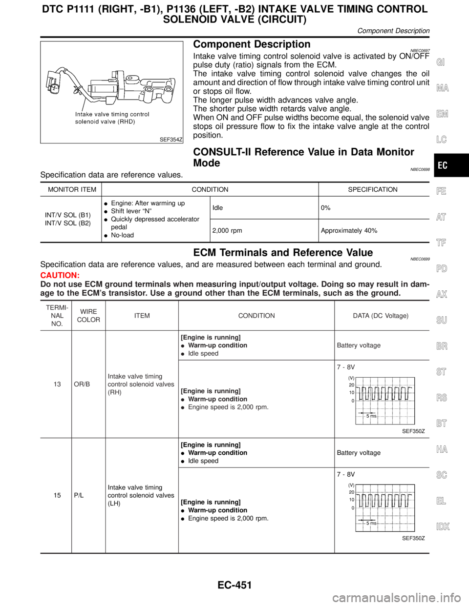
Component DescriptionNBEC0697Intake valve timing control solenoid valve is activated by ON/OFF
pulse duty (ratio) signals from the ECM.
The intake valve timing control solenoid valve changes the oil
amount and direction of flow through intake valve timing control unit
or stops oil flow.
The longer pulse width advances valve angle.
The shorter pulse width retards valve angle.
When ON and OFF pulse widths become equal, the solenoid valve
stops oil pressure flow to fix the intake valve angle at the control
position.
CONSULT-II Reference Value in Data Monitor
Mode
NBEC0698Specification data are reference values.
MONITOR ITEM CONDITION SPECIFICATION
INT/V SOL (B1)
INT/V SOL (B2)IEngine: After warming up
IShift lever ªNº
IQuickly depressed accelerator
pedal
INo-loadIdle 0%
2,000 rpm Approximately 40%
ECM Terminals and Reference ValueNBEC0699Specification data are reference values, and are measured between each terminal and ground.
CAUTION:
Do not use ECM ground terminals when measuring input/output voltage. Doing so may result in dam-
age to the ECM's transistor. Use a ground other than the ECM terminals, such as the ground.
TERMI-
NAL
NO.WIRE
COLORITEM CONDITION DATA (DC Voltage)
13 OR/BIntake valve timing
control solenoid valves
(RH)[Engine is running]
IWarm-up condition
IIdle speedBattery voltage
[Engine is running]
IWarm-up condition
IEngine speed is 2,000 rpm.7-8V
SEF350Z
15 P/LIntake valve timing
control solenoid valves
(LH)[Engine is running]
IWarm-up condition
IIdle speedBattery voltage
[Engine is running]
IWarm-up condition
IEngine speed is 2,000 rpm.7-8V
SEF350Z
GI
MA
EM
LC
FE
AT
TF
PD
AX
SU
BR
ST
RS
BT
HA
SC
EL
IDX
D T C P 1111(RIGHT, -B1), P1136 (LEFT, -B2) INTAKE VALVE TIMING CONTROL
SOLENOID VALVE (CIRCUIT)
Component Description
EC-451
Page 990 of 2395

Diagnostic ProcedureNBEC0704
1 CHECK OVERALL FUNCTION
With CONSULT-II
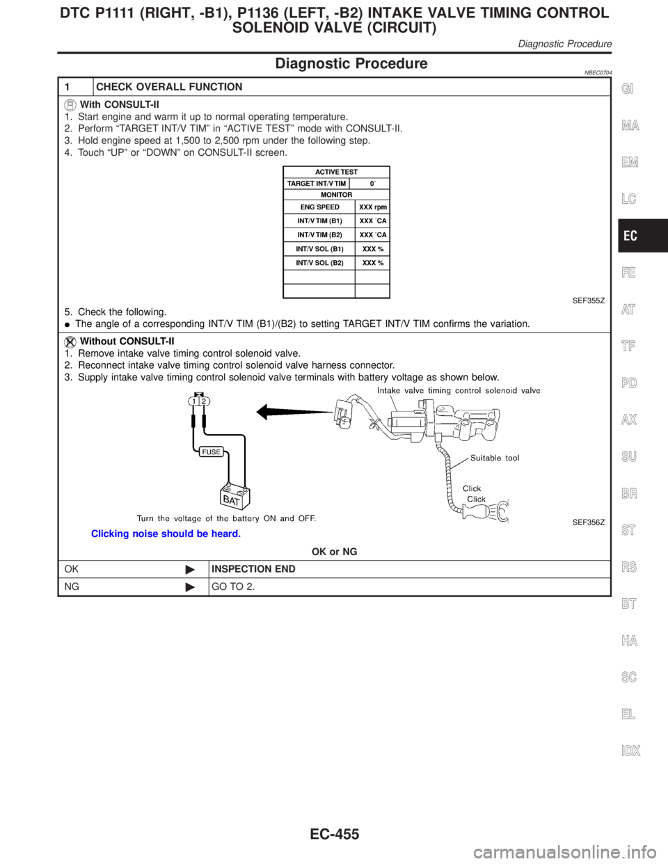
1. Start engine and warm it up to normal operating temperature.
2. Perform ªTARGET INT/V TIMº in ªACTIVE TESTº mode with CONSULT-II.
3. Hold engine speed at 1,500 to 2,500 rpm under the following step.
4. Touch ªUPº or ªDOWNº on CONSULT-II screen.
SEF355Z
5. Check the following.
IThe angle of a corresponding INT/V TIM (B1)/(B2) to setting TARGET INT/V TIM confirms the variation.
Without CONSULT-II
1. Remove intake valve timing control solenoid valve.
2. Reconnect intake valve timing control solenoid valve harness connector.
3. Supply intake valve timing control solenoid valve terminals with battery voltage as shown below.
SEF356Z
Clicking noise should be heard.
OK or NG
OK©INSPECTION END
NG©GO TO 2.
GI
MA
EM
LC
FE
AT
TF
PD
AX
SU
BR
ST
RS
BT
HA
SC
EL
IDX
D T C P 1111(RIGHT, -B1), P1136 (LEFT, -B2) INTAKE VALVE TIMING CONTROL
SOLENOID VALVE (CIRCUIT)
Diagnostic Procedure
EC-455
Page 994 of 2395

SEF002Z
COMPONENT DESCRIPTIONNBEC0523S02Swirl Control Valve Control Solenoid ValveNBEC0523S0201The swirl control valve control solenoid valve responds to signals
from the ECM. When the ECM sends an ON (ground) signal, the
solenoid valve is bypassed to apply intake manifold vacuum to the
swirl control valve actuator. This operation closes the swirl control
valve. When the ECM sends an OFF signal, the vacuum signal is
cut and the swirl control valve opens.
CONSULT-II Reference Value in Data Monitor
Mode
NBEC0524Specification data are reference values.
MONITOR ITEM CONDITION SPECIFICATION
SWRL CONT S/VIEngine speed: IdleEngine coolant temperature is
between 15ÉC (59ÉF) to 50ÉC
(122ÉF).ON
Engine coolant temperature is
above 55ÉC (131ÉF).OFF
ECM Terminals and Reference ValueNBEC0673Specification data are reference values and are measured between each terminal and ground.
CAUTION:
Do not use ECM ground terminals when measuring input/output voltage. Doing so may result in dam-
age to the ECM's transistor. Use a ground other than ECM terminals, such as the ground.
TERMI-
NAL
NO.WIRE
COLORITEM CONDITION DATA (DC Voltage)
29 GSwirl control valve con-
trol solenoid valve[Engine is running]
IIdle speed
IEngine coolant temperature is between 15 to
50ÉC (59 to 122ÉF).0 - 1.0V
[Engine is running]
IIdle speed
IEngine coolant temperature is above 55ÉC
(131ÉF).BATTERY VOLTAGE
(11 - 14V)
On Board Diagnosis LogicNBEC0526Malfunction is detected when
(Malfunction A)An improper voltage signal is sent to ECM through
swirl control valve control solenoid valve,
(Malfunction B)The vacuum signal is not sent to swirl control
valve under specified driving conditions, even though swirl control
valve control solenoid valve is ON,
(Malfunction C)The vacuum signal is sent to swirl control valve
even though swirl control valve control solenoid valve is OFF.
GI
MA
EM
LC
FE
AT
TF
PD
AX
SU
BR
ST
RS
BT
HA
SC
EL
IDX
DTC P1130 SWIRL CONTROL VALVE CONTROL SOLENOID VALVE
Description (Cont'd)
EC-459
Page 996 of 2395

SEF174Y
PROCEDURE FOR MALFUNCTION BNBEC0528S02TESTING CONDITION:
IFor best results, perform the test at a temperature above
5ÉC (41ÉF).
IBefore performing the following procedure, confirm that
battery voltage is more than 10V at idle, then stop engine
immediately.
With CONSULT-IINBEC0528S02011) Turn ignition switch ªOFFº and wait at least 10 seconds.
2) Turn ignition switch ªONº.
3) Check ªCOOLAN TEMP/Sº in ªDATA MONITORº mode with
CONSULT-II.
4) Confirm COOLAN TEMP/S value is 40ÉC (104ÉF) or less.
If the value is more than 40ÉC (104ÉF), park the vehicle in a
cool place and retry from step 1.
5) Start engine and wait until COOLAN TEMP/S value increases
to more than 55ÉC (131ÉF).
If 1st trip DTC is detected, go to ªDiagnostic Procedureº,
EC-463.
With GSTNBEC0528S0202Follow the procedure ªWith CONSULT-IIº above.
SEF174Y
PROCEDURE FOR MALFUNCTION CNBEC0528S03TESTING CONDITION:
IFor best results, perform the test at a temperature above
5ÉC (41ÉF).
IBefore performing the following procedure, confirm that
battery voltage is more than 10V at idle.
With CONSULT-IINBEC0528S03011) Start engine and warm it up to normal operating temperature.
2) Turn ignition switch ªOFFº and wait at least 10 seconds.
3) Turn ignition switch ªONº again and select ªDATA MONITORº
mode with CONSULT-II.
4) Start engine and let it idle for at least 20 seconds. If 1st trip
DTC is detected, go to ªDiagnostic Procedureº, EC-463.
With GSTNBEC0528S0302Follow the procedure ªWith CONSULT-IIº above.
GI
MA
EM
LC
FE
AT
TF
PD
AX
SU
BR
ST
RS
BT
HA
SC
EL
IDX
DTC P1130 SWIRL CONTROL VALVE CONTROL SOLENOID VALVE
DTC Confirmation Procedure (Cont'd)
EC-461
Page 1026 of 2395

On Board Diagnosis LogicNBEC0282HThe closed loop control has the one trip detection logic.
Malfunction is detected when the closed loop control function for
right bank does not operate even when vehicle is driving in the
specified condition, the closed loop control function for left bank
does not operate even when vehicle is driving in the specified
condition.
Possible CauseNBEC0531IThe front heated oxygen sensor circuit is open or shorted.
IHeated oxygen sensor 1 (front)
IHeated oxygen sensor 1 heater (front)
DTC Confirmation ProcedureNBEC0283CAUTION:
Always drive vehicle at a safe speed.
NOTE:
If ªDTC Confirmation Procedureº has been previously conducted,
always turn ignition switch ªOFFº and wait at least 10 seconds
before conducting the next test.
TESTING CONDITION:
INever raise engine speed above 3,600 rpm during the
ªDTC Confirmation Procedureº. If the engine speed limit is
exceeded, retry the procedure from step 2.
IBefore performing the following procedure, confirm that
battery voltage is more than 11V at idle.
SEF063Y
WITH CONSULT-IINBEC0283S011) Start engine and warm it up to normal operating temperature.
2) Select ªDATA MONITORº mode with CONSULT-II.
3) Hold engine speed at 2,000 rpm and check one of the follow-
ing.
IªHO2S1 (B1)/(B2)º voltage should go above 0.70V at least
once.
IªHO2S1 (B1)/(B2)º voltage should go below 0.21V at least
once.
If the check result is NG, perform ªDiagnosis Procedureº,
EC-492.
GI
MA
EM
LC
FE
AT
TF
PD
AX
SU
BR
ST
RS
BT
HA
SC
EL
IDX
DTC P1148 (RIGHT BANK, -B1), P1168 (LEFT BANK, -B2) CLOSED LOOP
CONTROL
On Board Diagnosis Logic
EC-491
Page 1046 of 2395

On Board Diagnosis LogicNBEC0576Malfunction is detected when
(Malfunction A)120É signal is not entered to ECM for the first few
seconds during engine cranking,
(Malfunction B)120É signal is not entered to ECM during engine
running,
(Malfunction C)120É signal cycle excessively changes during
engine running.
FAIL-SAFE MODENBEC0576S01When the ECM enters the fail-safe mode, the MIL illuminates.
Detected items Engine operating condition in fail-safe mode
Crankshaft position sensor (REF)
circuitCompression TDC signal (120É signal) is controlled by camshaft position sensor (PHASE)
signal and crankshaft position sensor (POS) signal. Ignition timing will be delayed 0É to 2É.
Possible CauseNBEC0577IHarness or connectors
(The crankshaft position sensor (REF) circuit is open or
shorted.)
ICrankshaft position sensor (REF)
IStarter motor (Refer to SC section.)
IStarting system circuit (Refer to SC section.)
IDead (Weak) battery
DTC Confirmation ProcedureNBEC0578NOTE:
IPerform ªPROCEDURE FOR MALFUNCTION Aº first. If 1st
trip DTC cannot be confirmed, perform ªPROCEDURE
FOR MALFUNCTION B AND Cº.
IIf ªDTC Confirmation Procedureº has been previously
conducted, always turn ignition switch ªOFFº and wait at least
10 seconds before conducting the next test.
TESTING CONDITION:
Before performing the following procedure, confirm that bat-
tery voltage is more than 10.5V at idle.
SEF013Y
PROCEDURE FOR MALFUNCTION ANBEC0578S01With CONSULT-IINBEC0578S01011) Turn ignition switch ªONº.
2) Select ªDATA MONITORº mode with CONSULT-II.
3) Crank engine for at least 2 seconds.
4) If 1st trip DTC is detected, go to ªDiagnostic Procedureº,
EC-514.
With GSTNBEC0578S0102Follow the procedure ªWith CONSULT-IIº above.
GI
MA
EM
LC
FE
AT
TF
PD
AX
SU
BR
ST
RS
BT
HA
SC
EL
IDX
DTC P1335 CRANKSHAFT POSITION SENSOR (CKPS) (REF)
On Board Diagnosis Logic
EC-511
Page 1062 of 2395

IEVAP purge line rubber tube bent.
IBlocked or bent rubber tube to EVAP control system pressure
sensor
ILoose or disconnected rubber tube
IEVAP canister vent control valve and the circuit
IEVAP canister purge volume control solenoid valve
IAbsolute pressure sensor
IFuel tank temperature sensor
IO-ring of EVAP canister vent control valve is missing or dam-
aged.
IWater separator
IEVAP canister is saturated with water.
IFuel level sensor and the circuit
IEVAP control system pressure sensor
SEF881X
SEF882X
SEF883X
DTC Confirmation ProcedureNBEC0317CAUTION:
Never remove fuel filler cap during the DTC confirmation pro-
cedure.
NOTE:
IIf DTC P1441 is displayed with P0440, perform TROUBLE
DIAGNOSIS FOR DTC P1441 first.
IIf ªDIAGNOSTIC TROUBLE CODE CONFIRMATION PRO-
CEDUREº has been previously conducted, always turn
ignition switch ªOFFº and wait at least 5 seconds before
conducting the next test.
IAfter repair, make sure that the hoses and clips are
installed properly.
TESTING CONDITION:
IOpen engine hood before conducting following proce-
dure.
IIf any of following condition is met just before the DTC
confirmation procedure, leave the vehicle for more than 1
hour.
a)Fuel filler cap is removed.
b)Refilled or drained the fuel.
c)EVAP component parts is/are removed.
IBefore performing the following procedure, confirm that
battery voltage is more than 11V at idle.
With CONSULT-II
1) Turn ignition switch ªONº and select ªDATA MONITORº mode
with CONSULT-II.
2) Make sure the following conditions are met.
FUEL LEVEL SE: 1.08 - 0.2V
COOLAN TEMP/S: 0 - 32ÉC (32 - 90ÉF)
FUEL T/TMP SE: 0 - 35ÉC (32 - 95ÉF)
INT A/TEMP SE: More than 0ÉC (32ÉF)
If NG, turn ignition switch ªOFFº and leave the vehicle in a cool
GI
MA
EM
LC
FE
AT
TF
PD
AX
SU
BR
ST
RS
BT
HA
SC
EL
IDX
DTC P1441 EVAP CONTROL SYSTEM (VERY SMALL LEAK)
Possible Cause (Cont'd)
EC-527
Page 1077 of 2395

ECM Terminals and Reference ValueNBEC0678Specification data are reference values and are measured between each terminal and ground.
CAUTION:
Do not use ECM ground terminals when measuring input/output voltage. Doing so may result in dam-
age to the ECM's transistor. Use a ground other than ECM terminals, such as the ground.
TERMI-
NAL
NO.WIRE
COLORITEM CONDITION DATA (DC Voltage)
1 L/YEVAP canister purge
volume control sole-
noid valve[Engine is running]
IIdle speedBATTERY VOLTAGE
(11 - 14V)
SEF994U
[Engine is running]
IEngine speed is about 2,000 rpm (More than 100
seconds after starting engine).BATTERY VOLTAGE
(11 - 14V)
SEF995U
On Board Diagnosis LogicNBEC0322Malfunction is detected when the canister purge flow is detected
during the specified driving conditions, even when EVAP canister
purge volume control solenoid valve is completely closed.
Possible CauseNBEC0588IEVAP control system pressure sensor
IEVAP canister purge volume control solenoid valve (The valve
is stuck open.)
IEVAP canister vent control valve
IEVAP canister
IHoses
(Hoses are connected incorrectly or clogged.)
DTC P1444 EVAP CANISTER PURGE VOLUME CONTROL SOLENOID VALVE
ECM Terminals and Reference Value
EC-542