ECU INFINITI QX4 2001 Factory Service Manual
[x] Cancel search | Manufacturer: INFINITI, Model Year: 2001, Model line: QX4, Model: INFINITI QX4 2001Pages: 2395, PDF Size: 43.2 MB
Page 2114 of 2395
SRS020-B
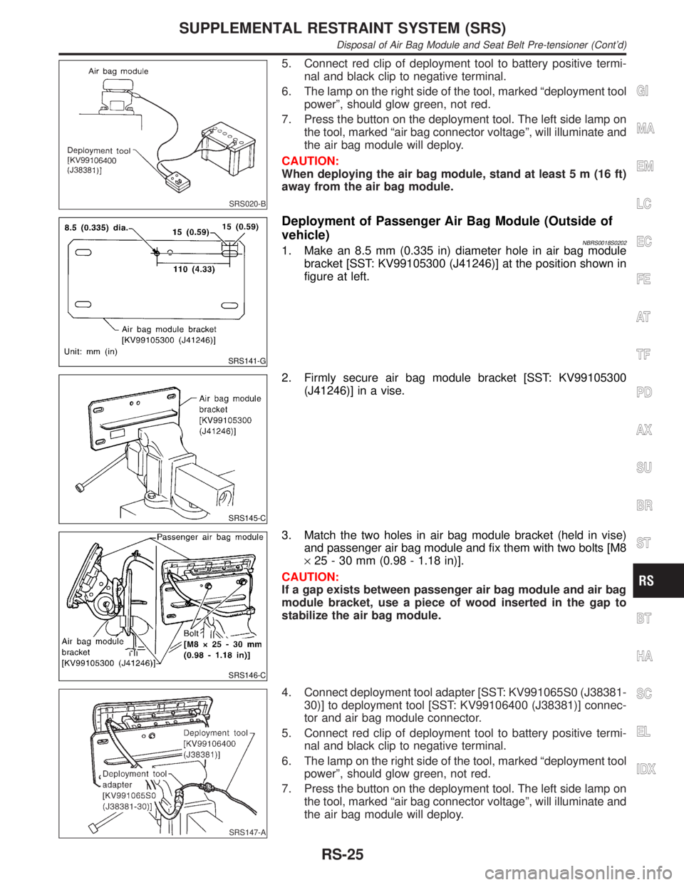
5. Connect red clip of deployment tool to battery positive termi-
nal and black clip to negative terminal.
6. The lamp on the right side of the tool, marked ªdeployment tool
powerº, should glow green, not red.
7. Press the button on the deployment tool. The left side lamp on
the tool, marked ªair bag connector voltageº, will illuminate and
the air bag module will deploy.
CAUTION:
When deploying the air bag module, stand at least 5 m (16 ft)
away from the air bag module.
SRS141-G
Deployment of Passenger Air Bag Module (Outside of
vehicle)
NBRS0018S02021. Make an 8.5 mm (0.335 in) diameter hole in air bag module
bracket [SST: KV99105300 (J41246)] at the position shown in
figure at left.
SRS145-C
2. Firmly secure air bag module bracket [SST: KV99105300
(J41246)] in a vise.
SRS146-C
3. Match the two holes in air bag module bracket (held in vise)
and passenger air bag module and fix them with two bolts [M8
´25 - 30 mm (0.98 - 1.18 in)].
CAUTION:
If a gap exists between passenger air bag module and air bag
module bracket, use a piece of wood inserted in the gap to
stabilize the air bag module.
SRS147-A
4. Connect deployment tool adapter [SST: KV991065S0 (J38381-
30)] to deployment tool [SST: KV99106400 (J38381)] connec-
tor and air bag module connector.
5. Connect red clip of deployment tool to battery positive termi-
nal and black clip to negative terminal.
6. The lamp on the right side of the tool, marked ªdeployment tool
powerº, should glow green, not red.
7. Press the button on the deployment tool. The left side lamp on
the tool, marked ªair bag connector voltageº, will illuminate and
the air bag module will deploy.
GI
MA
EM
LC
EC
FE
AT
TF
PD
AX
SU
BR
ST
BT
HA
SC
EL
IDX
SUPPLEMENTAL RESTRAINT SYSTEM (SRS)
Disposal of Air Bag Module and Seat Belt Pre-tensioner (Cont'd)
RS-25
Page 2115 of 2395
SRS020-B
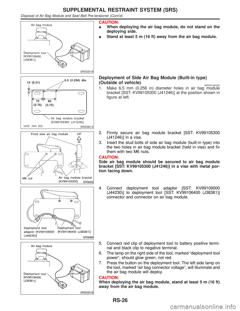
CAUTION:
IWhen deploying the air bag module, do not stand on the
deploying side.
IStand at least 5 m (16 ft) away from the air bag module.
SRS490-A
Deployment of Side Air Bag Module (Built-in type)
(Outside of vehicle)
NBRS0018S02031. Make 6.5 mm (0.256 in) diameter holes in air bag module
bracket [SST: KV99105300 (J41246)] at the position shown in
figure at left.
SRS628
2. Firmly secure air bag module bracket [SST: KV99105300
(J41246)] in a vise.
3. Insert the stud bolts of side air bag module (built-in type) into
the two holes in air bag module bracket (held in vise) and fix
them with two M6 nuts.
CAUTION:
Side air bag module should be secured to air bag module
bracket [SST: KV99105300 (J41246)] in a vise with metal por-
tion facing down.
SRS688
4. Connect deployment tool adapter [SST: KV99109000
(J44230)] to deployment tool [SST: KV99106400 (J38381)]
connector and connector on air bag module.
SRS020-B
5. Connect red clip of deployment tool to battery positive termi-
nal and black clip to negative terminal.
6. The lamp on the right side of the tool, marked ªdeployment tool
powerº, should glow green, not red.
7. Press the button on the deployment tool. The left side lamp on
the tool, marked ªair bag connector voltageº, will illuminate and
the air bag module will deploy.
CAUTION:
When deploying the air bag module, stand at least 5 m (16 ft)
away from the air bag module.
SUPPLEMENTAL RESTRAINT SYSTEM (SRS)
Disposal of Air Bag Module and Seat Belt Pre-tensioner (Cont'd)
RS-26
Page 2118 of 2395
Trouble Diagnoses Introduction=NBRS0040CAUTION:
IDo not use electrical test equipment on any circuit related to the SRS unless instructed to in this
Service Manual. Spiral cable and wiring harnesses covered with yellow insulation tape either just
before the harness connectors or for the complete harness are related to the SRS.
IDo not attempt to repair, splice or modify the SRS wiring harness. If the harness is damaged,
replace it with a new one.
IKeep ground portion clean.
DIAGNOSIS FUNCTIONNBRS0040S01The SRS self-diagnosis results can be read by using ªAIR BAGº warning lamp and/or CONSULT-II. The read-
ing of these results is accomplished using one of two modes Ð ªUser modeº and ªDiagnosis modeº.
The User mode is exclusively prepared for the customer (driver). This mode warns the driver of a system
malfunction through the operation of the ªAIR BAGº warning lamp.
The Diagnosis mode allows the technician to locate and inspect the malfunctioning part.
The mode applications for the ªAIR BAGº warning lamp and CONSULT-II are as follows:
User mode Diagnosis mode Display type
ªAIR BAGº warning lamp X X ON-OFF operation
CONSULT-II Ð X Monitoring
NOTE:
Seat belt pre-tensioner malfunction is indicated by ªAIR BAGº warning lamp.
DIAGNOSIS MODE FOR CONSULT-IINBRS0040S02IªSELF-DIAG [CURRENT]º
A current Self-diagnosis result (also indicated by the number of warning lamp flashes in the Diagnosis
mode) is displayed on the CONSULT-II screen in real time. This refers to a malfunctioning part requiring
repairs.
IªSELF-DIAG [PAST]º
Diagnosis results previously stored in the memory are displayed on the CONSULT-II screen. The stored
results are not erased until memory erasing is executed.
IªTROUBLE DIAG RECORDº
With TROUBLE DIAG RECORD, diagnosis results previously erased by a reset operation can be displayed
on the CONSULT-II screen.
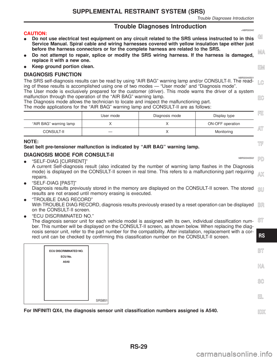
IªECU DISCRIMINATED NO.º
The diagnosis sensor unit for each vehicle model is assigned with its own, individual classification num-
ber. This number will be displayed on the CONSULT-II screen, as shown below. When replacing the diag-
nosis sensor unit, refer to the part number for the compatibility. After installation, replacement with a cor-
rect unit can be checked by confirming this classification number on the CONSULT-II screen.
SRS851
For INFINITI QX4, the diagnosis sensor unit classification numbers assigned is A540.
GI
MA
EM
LC
EC
FE
AT
TF
PD
AX
SU
BR
ST
BT
HA
SC
EL
IDX
SUPPLEMENTAL RESTRAINT SYSTEM (SRS)
Trouble Diagnoses Introduction
RS-29
Page 2149 of 2395
Part SRS is activated SRS is NOT activated
Harness and Connec-
tors1. Check connectors for poor connection, damage, and terminals for deformities.
2. Check harness for binding, chafing, cuts, or deformities.
3. If no damage is found, reinstall the harness and connectors.
4. DamagedÐREPLACE damaged section of harness. Do not attempt to repair, splice or modify any SRS
harness.
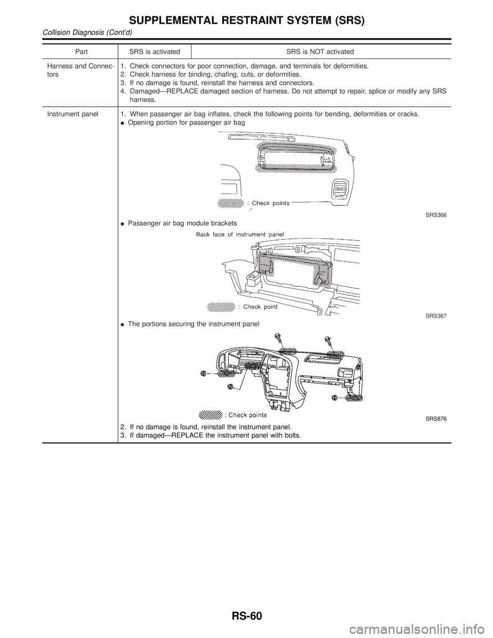
Instrument panel 1. When passenger air bag inflates, check the following points for bending, deformities or cracks.
IOpening portion for passenger air bag
SRS366
IPassenger air bag module brackets
SRS367
IThe portions securing the instrument panel
SRS876
2. If no damage is found, reinstall the instrument panel.
3. If damagedÐREPLACE the instrument panel with bolts.
SUPPLEMENTAL RESTRAINT SYSTEM (SRS)
Collision Diagnosis (Cont'd)
RS-60
Page 2193 of 2395
SRS266
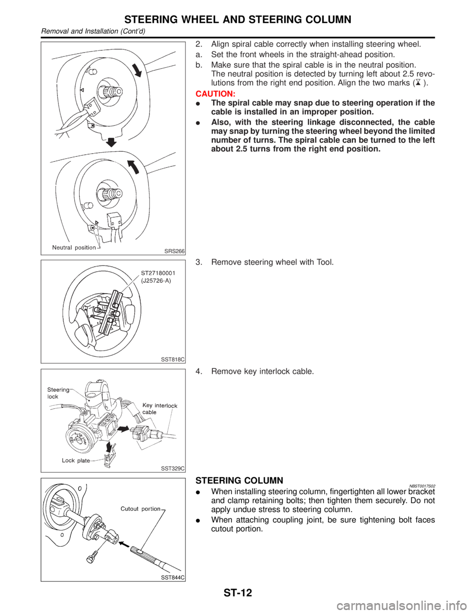
2. Align spiral cable correctly when installing steering wheel.
a. Set the front wheels in the straight-ahead position.
b. Make sure that the spiral cable is in the neutral position.
The neutral position is detected by turning left about 2.5 revo-
lutions from the right end position. Align the two marks (
).
CAUTION:
IThe spiral cable may snap due to steering operation if the
cable is installed in an improper position.
IAlso, with the steering linkage disconnected, the cable
may snap by turning the steering wheel beyond the limited
number of turns. The spiral cable can be turned to the left
about 2.5 turns from the right end position.
SST818C
3. Remove steering wheel with Tool.
SST329C
4. Remove key interlock cable.
SST844C
STEERING COLUMNNBST0017S02IWhen installing steering column, fingertighten all lower bracket
and clamp retaining bolts; then tighten them securely. Do not
apply undue stress to steering column.
IWhen attaching coupling joint, be sure tightening bolt faces
cutout portion.
STEERING WHEEL AND STEERING COLUMN
Removal and Installation (Cont'd)
ST-12
Page 2200 of 2395
in high-pressure connector. Take care to install the proper
O-ring.
SST616C
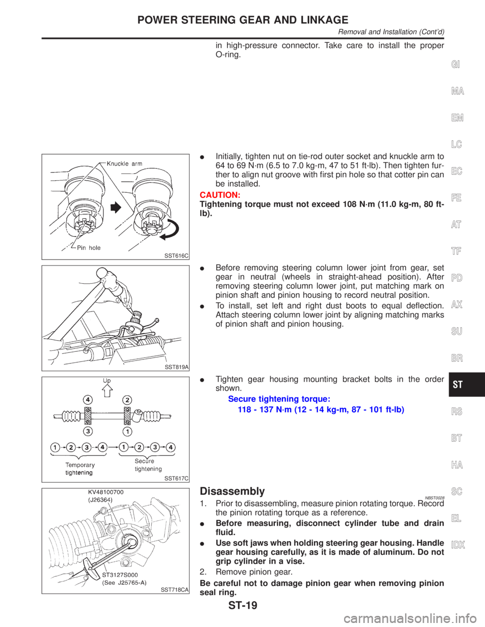
IInitially, tighten nut on tie-rod outer socket and knuckle arm to
64 to 69 N´m (6.5 to 7.0 kg-m, 47 to 51 ft-lb). Then tighten fur-
ther to align nut groove with first pin hole so that cotter pin can
be installed.
CAUTION:
Tightening torque must not exceed 108 N´m (11.0 kg-m, 80 ft-
lb).
SST819A
IBefore removing steering column lower joint from gear, set
gear in neutral (wheels in straight-ahead position). After
removing steering column lower joint, put matching mark on
pinion shaft and pinion housing to record neutral position.
ITo install, set left and right dust boots to equal deflection.
Attach steering column lower joint by aligning matching marks
of pinion shaft and pinion housing.
SST617C
ITighten gear housing mounting bracket bolts in the order
shown.
Secure tightening torque:
118 - 137 N´m (12 - 14 kg-m, 87 - 101 ft-lb)
SST718CA
DisassemblyNBST00281. Prior to disassembling, measure pinion rotating torque. Record
the pinion rotating torque as a reference.
IBefore measuring, disconnect cylinder tube and drain
fluid.
IUse soft jaws when holding steering gear housing. Handle
gear housing carefully, as it is made of aluminum. Do not
grip cylinder in a vise.
2. Remove pinion gear.
Be careful not to damage pinion gear when removing pinion
seal ring.
GI
MA
EM
LC
EC
FE
AT
TF
PD
AX
SU
BR
RS
BT
HA
SC
EL
IDX
POWER STEERING GEAR AND LINKAGE
Removal and Installation (Cont'd)
ST-19
Page 2202 of 2395
SST468C
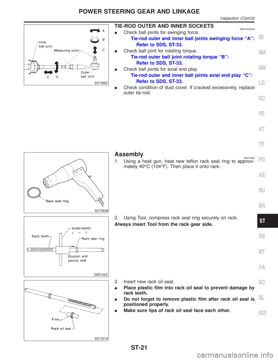
TIE-ROD OUTER AND INNER SOCKETSNBST0029S05ICheck ball joints for swinging force.
Tie-rod outer and inner ball joints swinging force ªAº:
Refer to SDS, ST-33.
ICheck ball joint for rotating torque.
Tie-rod outer ball joint rotating torque ªBº:
Refer to SDS, ST-33.
ICheck ball joints for axial end play.
Tie-rod outer and inner ball joints axial end play ªCº:
Refer to SDS, ST-33.
ICheck condition of dust cover. If cracked excessively, replace
outer tie-rod.
SST083B
AssemblyNBST00301. Using a heat gun, heat new teflon rack seal ring to approxi-
mately 40ÉC (104ÉF). Then place it onto rack.
SBR132C
2. Using Tool, compress rack seal ring securely on rack.
Always insert Tool from the rack gear side.
SST201A
3. Insert new rack oil seal.
IPlace plastic film into rack oil seal to prevent damage by
rack teeth.
IDo not forget to remove plastic film after rack oil seal is
positioned properly.
IMake sure lips of rack oil seal face each other.
GI
MA
EM
LC
EC
FE
AT
TF
PD
AX
SU
BR
RS
BT
HA
SC
EL
IDX
POWER STEERING GEAR AND LINKAGE
Inspection (Cont'd)
ST-21
Page 2212 of 2395
SST933C
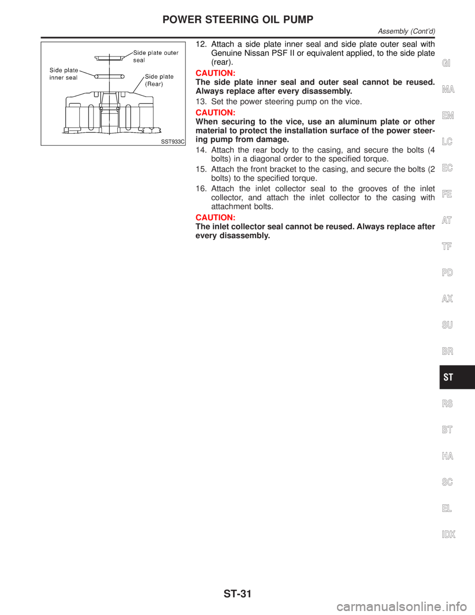
12. Attach a side plate inner seal and side plate outer seal with
Genuine Nissan PSF II or equivalent applied, to the side plate
(rear).
CAUTION:
The side plate inner seal and outer seal cannot be reused.
Always replace after every disassembly.
13. Set the power steering pump on the vice.
CAUTION:
When securing to the vice, use an aluminum plate or other
material to protect the installation surface of the power steer-
ing pump from damage.
14. Attach the rear body to the casing, and secure the bolts (4
bolts) in a diagonal order to the specified torque.
15. Attach the front bracket to the casing, and secure the bolts (2
bolts) to the specified torque.
16. Attach the inlet collector seal to the grooves of the inlet
collector, and attach the inlet collector to the casing with
attachment bolts.
CAUTION:
The inlet collector seal cannot be reused. Always replace after
every disassembly.
GI
MA
EM
LC
EC
FE
AT
TF
PD
AX
SU
BR
RS
BT
HA
SC
EL
IDX
POWER STEERING OIL PUMP
Assembly (Cont'd)
ST-31
Page 2268 of 2395

SMT962D
DATA MONITORNBTF0012S03CONSULT-II Setting ProcedureNBTF0012S03011. Turn ignition switch to ªOFFº position.
2. Connect CONSULT-II to data link connector, which is located
in instrument lower panel on driver side.
3. Turn ignition switch to ªONº position.
4. Touch ªSTARTº.
SMT964D
5. Touch ªALL MODE 4WDº.
SMT965D
6. Touch ªDATA MONITORº.
SAT972J
7. Touch ªECU INPUT SIGNALSº or ªMAIN SIGNALSº.
8. Select ªNumerical Displayº, ªBar Chart Displayº or ªLine Graph
Displayº.
9. Touch ªSETTINGº to set record conditions.
SAT973J
10. Touch ªAUTO TRIGº or ªMANU TRIGº.
11. Return to ªSELECT MONITOR ITEMº on ªDATA MONITORº
screen and touch ªSTARTº.
GI
MA
EM
LC
EC
FE
AT
PD
AX
SU
BR
ST
RS
BT
HA
SC
EL
IDX
ON BOARD DIAGNOSTIC SYSTEM DESCRIPTION
Trouble Diagnosis with CONSULT-II (Cont'd)
TF-33
Page 2269 of 2395
![INFINITI QX4 2001 Factory Service Manual SMT963D
12. Monitored data are displayed.
DATA MONITOR ITEMSNBTF0012S04q: StandardH: Option
Item [Unit]Monitor item
Remarks
ECU input
signalsMain sig-
nalsItem menu
selection
Revolution sensor-front [ INFINITI QX4 2001 Factory Service Manual SMT963D
12. Monitored data are displayed.
DATA MONITOR ITEMSNBTF0012S04q: StandardH: Option
Item [Unit]Monitor item
Remarks
ECU input
signalsMain sig-
nalsItem menu
selection
Revolution sensor-front [](/img/42/57027/w960_57027-2268.png)
SMT963D
12. Monitored data are displayed.
DATA MONITOR ITEMSNBTF0012S04q: StandardH: Option
Item [Unit]Monitor item
Remarks
ECU input
signalsMain sig-
nalsItem menu
selection
Revolution sensor-front [km/h (MPH)]qHRevolution sensor installed on T/F
Revolution sensor-rear [km/h (MPH)]qHVehicle speed sensor´A/T
Engine speed [rpm]qH
Throttle position sensor [V]qH
Transfer fluid temperature sensor [V]qH
Battery voltage [V]qH
2WD switch [ON-OFF]qH2WD switch of 4WD shift switch
AUTO switch [ON-OFF]qHAUTO switch of 4WD shift switch
Lock switch [ON-OFF]qH4H switch of 4WD shift switch
4L switch [ON-OFF]qH4LO switch of 4WD shift switch
N position switch TF [ON-OFF]qHN position switch of transfer
Line pressure switch [ON-OFF]qHLine pressure switch
Clutch pressure switch [ON-OFF]qHClutch pressure switch
ATP switch [ON-OFF]qH
N position switch [ON-OFF]qHªNº position on A/T PNP switch
R position switch [ON-OFF]qHªRº position on A/T PNP switch
P position switch [ON-OFF]qHªPº position on A/T PNP switch
Closed throttle position switch
[ON/OFF]qHIdle contact of throttle position switch
ABS operation switch [ON-OFF]qHABS operation switch
Wait detection switch [ON-OFF]qH
Throttle openingqHThrottle opening recognized by transfer control
unit
4WD-modeqH4WD-mode recognized by transfer control unit
(2W, AUTO, 4H & 4LO)
Vehicle speed comp [km/h (MPH)]qHVehicle speed recognized by transfer control
unit
*Control torque [N´m (kg-m, ft-lb)]qHCalculated torque recognized by transfer control
unit
ON BOARD DIAGNOSTIC SYSTEM DESCRIPTION
Trouble Diagnosis with CONSULT-II (Cont'd)
TF-34