ECU INFINITI QX4 2001 Factory Service Manual
[x] Cancel search | Manufacturer: INFINITI, Model Year: 2001, Model line: QX4, Model: INFINITI QX4 2001Pages: 2395, PDF Size: 43.2 MB
Page 1783 of 2395
NBGI0006
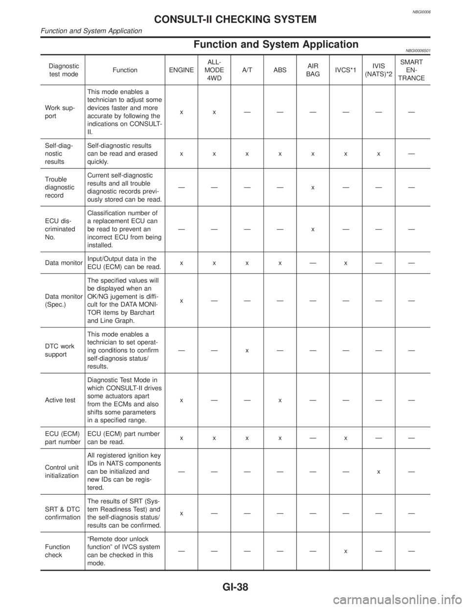
Function and System ApplicationNBGI0006S01
Diagnostic
test modeFunction ENGINEALL-
MODE
4WDA/T ABSAIR
BAGIVCS*1IVIS
(NATS)*2SMART
EN-
TRANCE
Work sup-
portThis mode enables a
technician to adjust some
devices faster and more
accurate by following the
indications on CONSULT-
II.x x ÐÐÐÐÐÐ
Self-diag-
nostic
resultsSelf-diagnostic results
can be read and erased
quickly.xxxxxxxÐ
Trouble
diagnostic
recordCurrent self-diagnostic
results and all trouble
diagnostic records previ-
ously stored can be read.ÐÐÐÐ x ÐÐÐ
ECU dis-
criminated
No.Classification number of
a replacement ECU can
be read to prevent an
incorrect ECU from being
installed.ÐÐÐÐ x ÐÐÐ
Data monitorInput/Output data in the
ECU (ECM) can be read.x x x xÐxÐÐ
Data monitor
(Spec.)The specified values will
be displayed when an
OK/NG jugement is diffi-
cult for the DATA MONI-
TOR items by Barchart
and Line Graph.x ÐÐÐÐÐÐÐ
DTC work
supportThis mode enables a
technician to set operat-
ing conditions to confirm
self-diagnosis status/
results.ÐÐ x ÐÐÐÐÐ
Active testDiagnostic Test Mode in
which CONSULT-II drives
some actuators apart
from the ECMs and also
shifts some parameters
in a specified range.x ÐÐ x ÐÐÐÐ
ECU (ECM)
part numberECU (ECM) part number
can be read.x x x xÐxÐÐ
Control unit
initializationAll registered ignition key
IDs in NATS components
can be initialized and
new IDs can be regis-
tered.ÐÐÐÐÐÐ x Ð
SRT & DTC
confirmationThe results of SRT (Sys-
tem Readiness Test) and
the self-diagnosis status/
results can be confirmed.x ÐÐÐÐÐÐÐ
Function
checkªRemote door unlock
functionº of IVCS system
can be checked in this
mode.ÐÐÐÐÐ x ÐÐ
CONSULT-II CHECKING SYSTEM
Function and System Application
GI-38
Page 1793 of 2395

SGI989
2WD MODELSNBGI0008S0402INFINITI recommends that vehicle be towed with the driving (rear)
wheels off the ground as illustrated.
CAUTION:
IWhen towing manual or automatic transmission models
with the front wheels on the ground: Turn the ignition key
to the OFF position and secure the steering wheel in a
straightahead position with a rope or similar device. Never
place the ignition key in the LOCK position. This will result
in damage to the steering lock mechanism.
IWhen towing manual transmission models with the rear
wheels on the ground or four wheels on the ground (if you
do not use towing dollies): Always release the parking
brake and move the transmission shift lever to the N (neu-
tral) position.
Observe the following restricted towing speeds and distances.
Manual transmission models:
ISpeed: Below 95 km/h (60 MPH)
IDistance: Less than 800 km (500 miles)
If the speed or distance must necessarily be greater, remove the
propeller shaft beforehand to prevent damage to the transmission.
SGI950
4WD MODELSNBGI0008S0403INFINITI recommends that a dolly or a flat bed truck be used as
illustrated when towing all-mode 4WD models.
LIFTING POINTS AND TOW TRUCK TOWING
Tow Truck Towing (Cont'd)
GI-48
Page 1820 of 2395

RHA441GA
Transmission Data and Transmission OrderNBHA0014S0802Amplifier data is transmitted consecutively to each of the door motors following the form shown in figure below.
Start: Initial compulsory signal sent to each of the door motors.
Address: Data sent from the auto amplifier is selected according to data-based decisions made by the air mix
door motor and mode door motor.
If the addresses are identical, the opening angle data and error check signals are received by the door motor
LCUs. The LCUs then make the appropriate error decision. If the opening angle data is normal, door control
begins.
If an error exists, the received data is rejected and corrected data received. Finally, door control is based upon
the corrected opening angle data.
Opening angle: Data that shows the indicated door opening angle of each door motor.
Error check: Procedure by which sent and received data is checked for errors. Error data is then compiled.
The error check prevents corrupted data from being used by the air mix door motor and mode door motor.
Error data can be related to the following problems.
IAbnormal electrical frequency
IPoor electrical connections
ISignal leakage from transmission lines
ISignal level fluctuation
Stop signal: At the end of each transmission, a stop operation, in-operation, or internal problem message is
delivered to the auto amplifier. This completes one data transmission and control cycle.
RHA442G
Air Mix Door Control (Automatic Temperature Control)NBHA0014S0803The air mix door is automatically controlled so that in-vehicle temperature is maintained at a predetermined
value by: The temperature setting, ambient temperature, in-vehicle temperature and amount of sunload.
GI
MA
EM
LC
EC
FE
AT
TF
PD
AX
SU
BR
ST
RS
BT
SC
EL
IDX
DESCRIPTION
Features (Cont'd)
HA-21
Page 1884 of 2395

Air Mix Door Control SpecificationNBHA0059S03
RHA137G
RHA849E
COMPONENT DESCRIPTIONNBHA0060The air mix door motor is attached to the heater unit. It rotates so
that the air mix door is opened or closed to a position set by the
auto amplifier. Motor rotation is then conveyed through a shaft and
the air mix door position is then fed back to the auto amplifier by
PBR built-in air mix door motor.
RHA504G
SHA522EA
CONTROL LINKAGE ADJUSTMENTNBHA0099Air Mix Door (Water Cock)NBHA0099S011. Install air mix door motor on heater unit and connect it to main
harness.
2. Set up code No. 41 in Self-diagnosis STEP 4. Refer to HA-44.
3. Move air mix door lever by hand and hold it in full cold posi-
tion.
4. Attach air mix door lever to rod holder.
5. Make sure air mix door operates properly when changing from
code No.
toby pushing DEF switch.
Full cold Full hot
6. Set up code No.in Self-diagnosis STEP 4.
7. Attach water cock rod to air mix door lever and secure with clip.
8. Rotate air mix door lever (CLOCKWISE completely) and hold
water cock rod and link lever in the full cold position.
9. Attach water cock rod to link lever and secure with clip (white
mark on cable housing should be centered under the retaining
clip).
GI
MA
EM
LC
EC
FE
AT
TF
PD
AX
SU
BR
ST
RS
BT
SC
EL
IDX
TROUBLE DIAGNOSES
Air Mix Door Motor (Cont'd)
HA-85
Page 1956 of 2395
SHA708EA
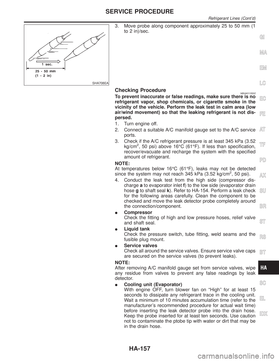
3. Move probe along component approximately 25 to 50 mm (1
to 2 in)/sec.
Checking ProcedureNBHA0115S02To prevent inaccurate or false readings, make sure there is no
refrigerant vapor, shop chemicals, or cigarette smoke in the
vicinity of the vehicle. Perform the leak test in calm area (low
air/wind movement) so that the leaking refrigerant is not dis-
persed.
1. Turn engine off.
2. Connect a suitable A/C manifold gauge set to the A/C service
ports.
3. Check if the A/C refrigerant pressure is at least 345 kPa (3.52
kg/cm
2, 50 psi) above 16ÉC (61ÉF). If less than specification,
recover/evacuate and recharge the system with the specified
amount of refrigerant.
NOTE:
At temperatures below 16ÉC (61ÉF), leaks may not be detected
since the system may not reach 345 kPa (3.52 kg/cm
2, 50 psi).
4. Conduct the leak test from the high side (compressor dis-
chargeato evaporator inletf) to the low side (evaporator drain
hosegto shaft sealk). Refer to HA-154. Perform a leak check
for the following areas carefully. Clean the component to be
checked and move the leak detector probe completely around
the connection/component.
ICompressor
Check the fitting of high and low pressure hoses, relief valve
and shaft seal.
ILiquid tank
Check the pressure switch, tube fitting, weld seams and the
fusible plug mount.
IService valves
Check all around the service valves. Ensure service valve caps
are secured on the service valves (to prevent leaks).
NOTE:
After removing A/C manifold gauge set from service valves, wipe
any residue from valves to prevent any false readings by leak
detector.
ICooling unit (Evaporator)
With engine OFF, turn blower fan on ªHighº for at least 15
seconds to dissipate any refrigerant trace in the cooling unit.
Wait a minimum of 10 minutes accumulation time (refer to the
manufacturer's recommended procedure for actual wait time)
before inserting the leak detector probe into the drain hose.
Keep the probe inserted for at least ten seconds. Use caution
not to contaminate the ptobe tip with water or dirt that may be
in the drain hose.
GI
MA
EM
LC
EC
FE
AT
TF
PD
AX
SU
BR
ST
RS
BT
SC
EL
IDX
SERVICE PROCEDURE
Refrigerant Lines (Cont'd)
HA-157
Page 1981 of 2395

SLC756A
CHECKING COOLING SYSTEM FOR LEAKSNBLC0016S04To check for leakage, apply pressure to the cooling system with a
tester.
Testing pressure:
157 kPa (1.6 kg/cm
2, 23 psi)
CAUTION:
Higher than the specified pressure may cause radiator
damage.
Water Pump
REMOVAL AND INSTALLATIONNBLC0017CAUTION:
IWhen removing water pump assembly, be careful not to
get coolant on drive belt.
IWater pump cannot be disassembled and should be
replaced as a unit.
IAfter installing water pump, connect hose and clamp
securely, then check for leaks using radiator cap tester.
SLC326B
SLC327B
REMOVALNBLC00181. Remove under cover.
2. Remove suspension member stay.
3. Drain coolant from radiator.
4. Remove radiator shrouds.
5. Remove drive belts.
6. Remove cooling fan.
7. Remove water drain plug on water pump side of cylinder block.
8. Remove chain tensioner cover and water pump cover.
ENGINE COOLING SYSTEM
System Check (Cont'd)
LC-12
Page 1982 of 2395

SLC328B
9. Pushing timing chain tensioner sleeve, apply a stopper pin so
it does not return. Then remove the chain tensioner assembly.
SLC941A
10. Remove the 3 water pump fixing bolts. Secure a gap between
water pump gear and timing chain, by turning crankshaft pul-
ley 20É backwards.
JLC357B
11. Put M8 bolts to two water pump fixing bolt holes.
GI
MA
EM
EC
FE
AT
TF
PD
AX
SU
BR
ST
RS
BT
HA
SC
EL
IDX
ENGINE COOLING SYSTEM
Water Pump (Cont'd)
LC-13
Page 1992 of 2395
SLC904-A
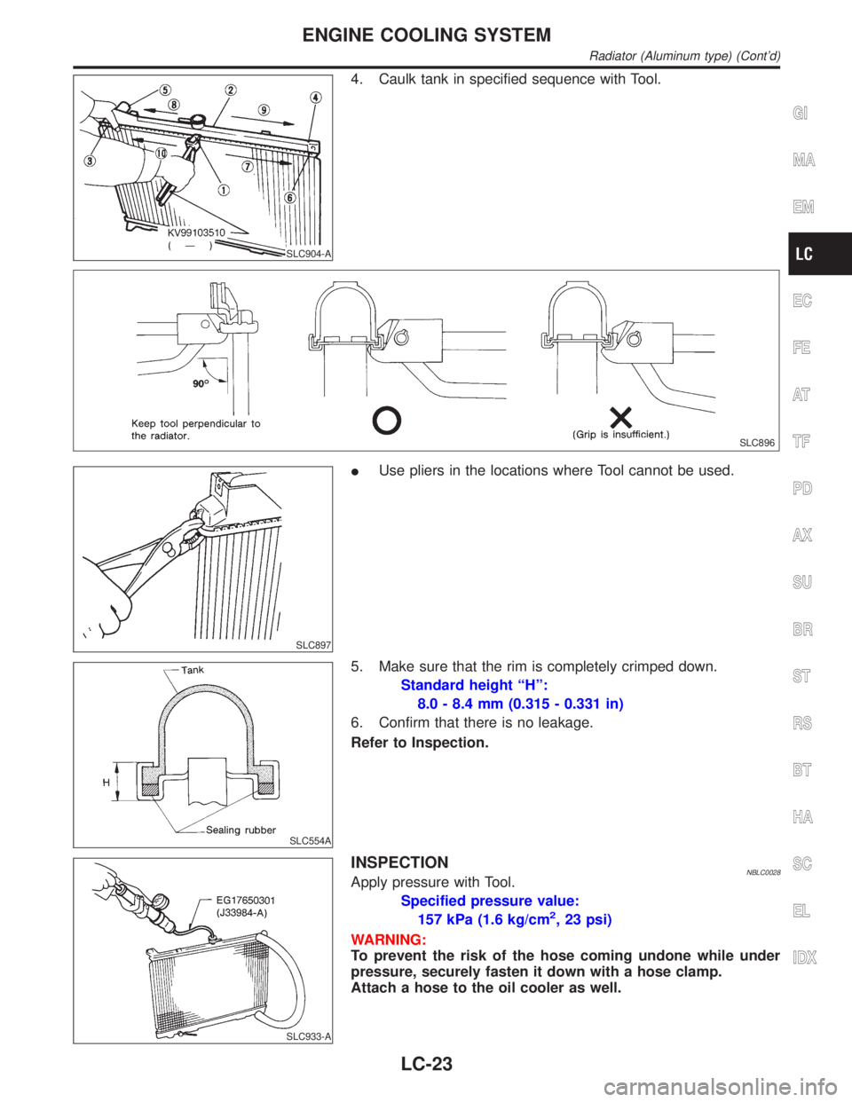
4. Caulk tank in specified sequence with Tool.
SLC896
SLC897
IUse pliers in the locations where Tool cannot be used.
SLC554A
5. Make sure that the rim is completely crimped down.
Standard height ªHº:
8.0 - 8.4 mm (0.315 - 0.331 in)
6. Confirm that there is no leakage.
Refer to Inspection.
SLC933-A
INSPECTIONNBLC0028Apply pressure with Tool.
Specified pressure value:
157 kPa (1.6 kg/cm
2, 23 psi)
WARNING:
To prevent the risk of the hose coming undone while under
pressure, securely fasten it down with a hose clamp.
Attach a hose to the oil cooler as well.
GI
MA
EM
EC
FE
AT
TF
PD
AX
SU
BR
ST
RS
BT
HA
SC
EL
IDX
ENGINE COOLING SYSTEM
Radiator (Aluminum type) (Cont'd)
LC-23
Page 1999 of 2395
NBMA0003
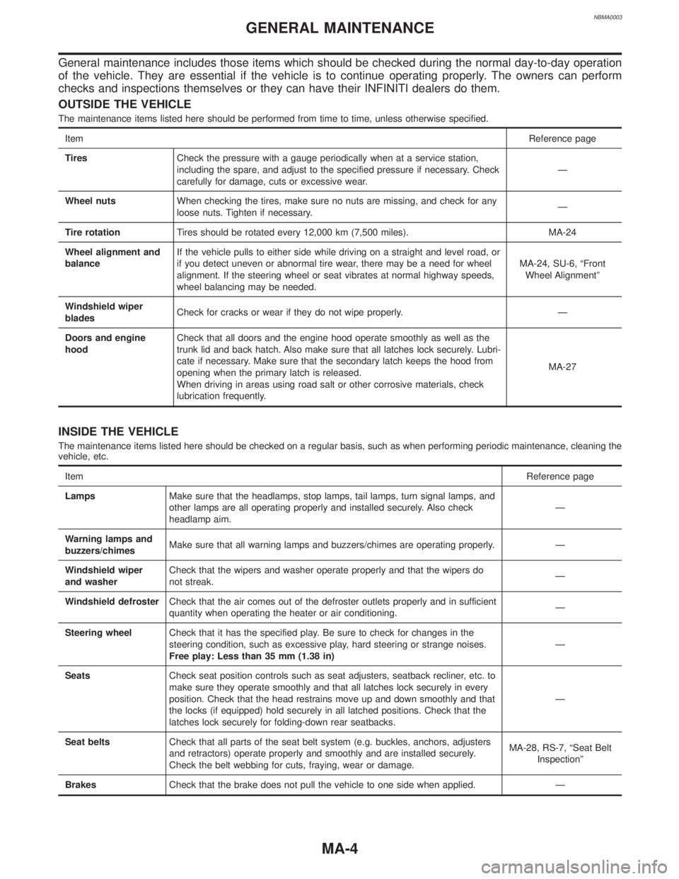
General maintenance includes those items which should be checked during the normal day-to-day operation
of the vehicle. They are essential if the vehicle is to continue operating properly. The owners can perform
checks and inspections themselves or they can have their INFINITI dealers do them.
OUTSIDE THE VEHICLE
The maintenance items listed here should be performed from time to time, unless otherwise specified.
ItemReference page
TiresCheck the pressure with a gauge periodically when at a service station,
including the spare, and adjust to the specified pressure if necessary. Check
carefully for damage, cuts or excessive wear.Ð
Wheel nutsWhen checking the tires, make sure no nuts are missing, and check for any
loose nuts. Tighten if necessary.Ð
Tire rotationTires should be rotated every 12,000 km (7,500 miles). MA-24
Wheel alignment and
balanceIf the vehicle pulls to either side while driving on a straight and level road, or
if you detect uneven or abnormal tire wear, there may be a need for wheel
alignment. If the steering wheel or seat vibrates at normal highway speeds,
wheel balancing may be needed.MA-24, SU-6, ªFront
Wheel Alignmentº
Windshield wiper
bladesCheck for cracks or wear if they do not wipe properly. Ð
Doors and engine
hoodCheck that all doors and the engine hood operate smoothly as well as the
trunk lid and back hatch. Also make sure that all latches lock securely. Lubri-
cate if necessary. Make sure that the secondary latch keeps the hood from
opening when the primary latch is released.
When driving in areas using road salt or other corrosive materials, check
lubrication frequently.MA-27
INSIDE THE VEHICLE
The maintenance items listed here should be checked on a regular basis, such as when performing periodic maintenance, cleaning the
vehicle, etc.
ItemReference page
LampsMake sure that the headlamps, stop lamps, tail lamps, turn signal lamps, and
other lamps are all operating properly and installed securely. Also check
headlamp aim.Ð
Warning lamps and
buzzers/chimesMake sure that all warning lamps and buzzers/chimes are operating properly. Ð
Windshield wiper
and washerCheck that the wipers and washer operate properly and that the wipers do
not streak.Ð
Windshield defrosterCheck that the air comes out of the defroster outlets properly and in sufficient
quantity when operating the heater or air conditioning.Ð
Steering wheelCheck that it has the specified play. Be sure to check for changes in the
steering condition, such as excessive play, hard steering or strange noises.
Free play: Less than 35 mm (1.38 in)Ð
SeatsCheck seat position controls such as seat adjusters, seatback recliner, etc. to
make sure they operate smoothly and that all latches lock securely in every
position. Check that the head restrains move up and down smoothly and that
the locks (if equipped) hold securely in all latched positions. Check that the
latches lock securely for folding-down rear seatbacks.Ð
Seat beltsCheck that all parts of the seat belt system (e.g. buckles, anchors, adjusters
and retractors) operate properly and smoothly and are installed securely.
Check the belt webbing for cuts, fraying, wear or damage.MA-28, RS-7, ªSeat Belt
Inspectionº
BrakesCheck that the brake does not pull the vehicle to one side when applied. Ð
GENERAL MAINTENANCE
MA-4
Page 2000 of 2395
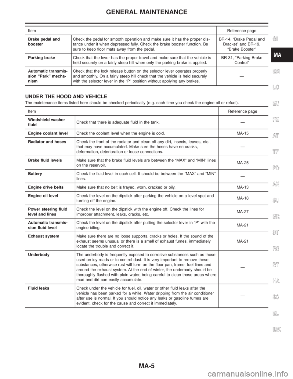
ItemReference page
Brake pedal and
boosterCheck the pedal for smooth operation and make sure it has the proper dis-
tance under it when depressed fully. Check the brake booster function. Be
sure to keep floor mats away from the pedal.BR-14, ªBrake Pedal and
Bracketº and BR-19,
ªBrake Boosterº
Parking brakeCheck that the lever has the proper travel and make sure that the vehicle is
held securely on a fairly steep hill when only the parking brake is applied.BR-31, ªParking Brake
Controlº
Automatic transmis-
sion ªParkº mecha-
nismCheck that the lock release button on the selector lever operates properly
and smoothly. On a fairly steep hill check that the vehicle is held securely
with the selector lever in the ªPº position without applying any brakes.Ð
UNDER THE HOOD AND VEHICLE
The maintenance items listed here should be checked periodically (e.g. each time you check the engine oil or refuel).
ItemReference page
Windshield washer
fluidCheck that there is adequate fluid in the tank. Ð
Engine coolant levelCheck the coolant level when the engine is cold. MA-15
Radiator and hosesCheck the front of the radiator and clean off any dirt, insects, leaves, etc.,
that may have accumulated. Make sure the hoses have no cracks,
deformation, deterioration or loose connections.Ð
Brake fluid levelsMake sure that the brake fluid levels are between the ªMAXº and ªMINº lines
on the reservoir.MA-25
BatteryCheck the fluid level in each cell. It should be between the ªMAXº and ªMINº
lines.Ð
Engine drive beltsMake sure that no belt is frayed, worn, cracked or oily. MA-13
Engine oil levelCheck the level on the dipstick after parking the vehicle on a level spot and
turning off the engine.MA-18
Power steering fluid
level and linesCheck the level on the dipstick with the engine off. Check the lines for
improper attachment, leaks, cracks, etc.MA-27
Automatic transmis-
sion fluid levelCheck the level on the dipstick after putting the selector lever in ªPº with the
engine idling.MA-21
Exhaust systemMake sure there are no loose supports, cracks or holes. If the sound of the
exhaust seems unusual or there is a smell of exhaust fumes, immediately
locate the trouble and correct it.MA-21
UnderbodyThe underbody is frequently exposed to corrosive substances such as those
used on icy roads or to control dust. It is very important to remove these
substances, otherwise rust will form on the floor pan, frame, fuel lines and
around the exhaust system. At the end of winter, the underbody should be
thoroughly flushed with plain water, being careful to clean those areas where
mud and dirt can easily accumulate.Ð
Fluid leaksCheck under the vehicle for fuel, oil, water or other fluid leaks after the
vehicle has been parked for a while. Water dripping from the air conditioner
after use is normal. If you should notice any leaks or gasoline fumes are
evident, check for the cause and correct it immediately.Ð
GI
EM
LC
EC
FE
AT
TF
PD
AX
SU
BR
ST
RS
BT
HA
SC
EL
IDX
GENERAL MAINTENANCE
MA-5