elec INFINITI QX4 2001 Factory Service Manual
[x] Cancel search | Manufacturer: INFINITI, Model Year: 2001, Model line: QX4, Model: INFINITI QX4 2001Pages: 2395, PDF Size: 43.2 MB
Page 599 of 2395

SEF170Z
*1 EC-60 *2 EC-64 *3 EC-65
How to Display SRT CodeNBEC0031S0301With CONSULT-II
Selecting ªSRT STATUSº in ªDTC CONFIRMATIONº mode with CONSULT-II.
For items whose SRT codes are set, a ªCMPLTº is displayed on the CONSULT-II screen; for items whose SRT
codes are not set, ªINCMPº is displayed.
With GST
Selecting Mode 1 with GST (Generic Scan Tool)
A sample of CONSULT-II display for SRT code is shown below.
ªINCMPº means the self-diagnosis is incomplete and SRT is not set. ªCMPLTº means the self-diagnosis is
complete and SRT is set.
ON BOARD DIAGNOSTIC SYSTEM DESCRIPTION
Emission-related Diagnostic Information (Cont'd)
EC-64
Page 602 of 2395

IThe time required for each diagnosis varies with road surface conditions, weather, altitude, individual driv-
ing habits, etc.
Zone A refers to the range where the time required, for the diagnosis under normal conditions*, is the
shortest.
Zone B refers to the range where the diagnosis can still be performed if the diagnosis is not completed
within zone A.
*: Normal conditions refer to the following:
þ Sea level
þ Flat road
þ Ambient air temperature: 20 - 30ÉC (68 - 86ÉF)
þ Diagnosis is performed as quickly as possible under normal conditions.
Under different conditions [For example: ambient air temperature other than 20 - 30ÉC (68 - 86ÉF)], diag-
nosis may also be performed.
Pattern 1:
IThe engine is started at the engine coolant temperature of þ10 to 35ÉC (14 to 95ÉF)
(where the voltage between the ECM terminal 70 and ground is 3.0 - 4.3V).
IThe engine must be operated at idle speed until the engine coolant temperature is greater than 70ÉC
(158ÉF) (where the voltage between the ECM terminal 70 and ground is lower than 1.4V).
IThe engine is started at the fuel tank temperature of warmer than 0ÉC (32ÉF) (where the voltage
between the ECM terminal 92 and ground is less than 4.1V).
Pattern 2:
IWhen steady-state driving is performed again even after it is interrupted, each diagnosis can be conducted.
In this case, the time required for diagnosis may be extended.
Pattern 3:
IThe driving pattern outlined in *2 must be repeated at least 3 times.
Pattern 4:
ITests are performed after the engine has been operated for at least 17 minutes.
IThe accelerator pedal must be held very steady during steady-state driving.
IIf the accelerator pedal is moved, the test must be conducted all over again.
*1: Depress the accelerator pedal until vehicle speed is 90 km/h (56 MPH), then release the accelerator pedal
and keep it released for more than 10 seconds. Depress the accelerator pedal until vehicle speed is 90 km/h
(56 MPH) again.
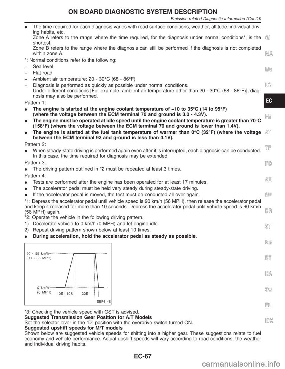
*2: Operate the vehicle in the following driving pattern.
1) Decelerate vehicle to 0 km/h (0 MPH) and let engine idle.
2) Repeat driving pattern shown below at least 10 times.
IDuring acceleration, hold the accelerator pedal as steady as possible.
SEF414S
*3: Checking the vehicle speed with GST is advised.
Suggested Transmission Gear Position for A/T Models
Set the selector lever in the ªDº position with the overdrive switch turned ON.
Suggested upshift speeds for M/T models
Shown below are suggested vehicle speeds for shifting into a higher gear. These suggestions relate to fuel
economy and vehicle performance. Actual upshift speeds will vary according to road conditions, the weather
and individual driving habits.
GI
MA
EM
LC
FE
AT
TF
PD
AX
SU
BR
ST
RS
BT
HA
SC
EL
IDX
ON BOARD DIAGNOSTIC SYSTEM DESCRIPTION
Emission-related Diagnostic Information (Cont'd)
EC-67
Page 608 of 2395

SEF823YA
The emission related diagnostic information in the ECM can be erased by selecting ªERASEº in the ªSELF-
DIAG RESULTSº mode with CONSULT-II.
How to Erase DTC (With GST)NBEC0031S0602NOTE:
If the DTC is not for A/T related items (see EC-8), skip step 2.
1. If the ignition switch stays ªONº after repair work, be sure to turn ignition switch ªOFFº once. Wait at least
10 seconds and then turn it ªONº (engine stopped) again.
2. Perform ªSELF-DIAGNOSTIC PROCEDURE (Without CONSULT-II)º in AT section titled ªTROUBLE
DIAGNOSISº, ªSelf-diagnosisº. (The engine warm-up step can be skipped when performing the diagnosis
only to erase the DTC.)
3. Select Mode 4 with GST (Generic Scan Tool).
The emission related diagnostic information in the ECM can be erased by selecting Mode 4 with GST.
IIf the battery is disconnected, the emission-related diagnostic information will be lost after approx.
24 hours.
IThe following data are cleared when the ECM memory is erased.
1) Diagnostic trouble codes
2) 1st trip diagnostic trouble codes
3) Freeze frame data
4) 1st trip freeze frame data
5) System readiness test (SRT) codes
6) Test values
7) Others
GI
MA
EM
LC
FE
AT
TF
PD
AX
SU
BR
ST
RS
BT
HA
SC
EL
IDX
ON BOARD DIAGNOSTIC SYSTEM DESCRIPTION
Emission-related Diagnostic Information (Cont'd)
EC-73
Page 623 of 2395
![INFINITI QX4 2001 Factory Service Manual Monitored item [Unit]ECM
input
signalsMain
signalsDescription Remarks
INT/A TEMP SE
[ÉC] or [ÉF]qqIThe intake air temperature determined
by the signal voltage of the intake air
temperature sensor is INFINITI QX4 2001 Factory Service Manual Monitored item [Unit]ECM
input
signalsMain
signalsDescription Remarks
INT/A TEMP SE
[ÉC] or [ÉF]qqIThe intake air temperature determined
by the signal voltage of the intake air
temperature sensor is](/img/42/57027/w960_57027-622.png)
Monitored item [Unit]ECM
input
signalsMain
signalsDescription Remarks
INT/A TEMP SE
[ÉC] or [ÉF]qqIThe intake air temperature determined
by the signal voltage of the intake air
temperature sensor is indicated.
EVAP SYS PRES [V]qIThe signal voltage of EVAP control sys-
tem pressure sensor is displayed.
ABSOL PRES/SE [V]qIThe signal voltage of the absolute pres-
sure sensor is displayed.
FUEL LEVEL SE [V]qIThe signal voltage of the fuel level sen-
sor is displayed.
START SIGNAL
[ON/OFF]qqIIndicates [ON/OFF] condition from the
starter signal.IAfter starting the engine, [OFF] is dis-
played regardless of the starter signal.
CLSD THL POS
[ON/OFF]qqIIndicates idle position [ON/OFF] com-
puted by ECM according to the throttle
position sensor signal.
CLSD THL/P SW
[ON/OFF]qIIndicates mechanical contact [ON/OFF]
condition of the closed throttle position
switch.
AIR COND SIG
[ON/OFF]qqIIndicates [ON/OFF] condition of the air
conditioner switch as determined by the
air conditioner signal.
P/N POSI SW
[ON/OFF]qqIIndicates [ON/OFF] condition from the
park/neutral position (PNP) switch sig-
nal.
PW/ST SIGNAL
[ON/OFF]qqI[ON/OFF] condition of the power steer-
ing oil pressure switch determined by
the power steering oil pressure signal is
indicated.
LOAD SIGNAL
[ON/OFF]qqIIndicates [ON/OFF] condition from the
electrical load signal and/or lighting
switch.
ON ... rear defogger is operating and/or
lighting switch is on.
OFF ... rear defogger is not operating
and lighting switch is not on.
IGNITION SW
[ON/OFF]qIIndicates [ON/OFF] condition from igni-
tion switch.
SWRL CONT S/V
[ON/OFF]qIThe control condition of the swirl con-
trol valve control solenoid valve (deter-
mined by ECM according to the input
signals) is indicated.
ION ... Swirl control valve is closed.
OFF ... Swirl control valve is opened.
INJ PULSE-B1
[msec]q
IIndicates the actual fuel injection pulse
width compensated by ECM according
to the input signals.IWhen the engine is stopped, a certain
computed value is indicated.
INJ PULSE-B2
[msec]
B/FUEL SCHDL
[msec]qIªBase fuel scheduleº indicates the fuel
injection pulse width programmed into
ECM, prior to any learned on board
correction.
ON BOARD DIAGNOSTIC SYSTEM DESCRIPTION
CONSULT-II (Cont'd)
EC-88
Page 628 of 2395

DTC Work Support ModeNBEC0034S0802
Test mode Test item Condition Reference page
EVAPORATIVE SYSTEMEVAP SML LEAK P0440
Refer to corresponding
trouble diagnosis for
DTC.EC-352
EVAP VERY SML LEAK P1441 EC-526
PURG VOL CN/V P1444 EC-541
PURGE FLOW P1447 EC-561
VC CUT/V BP/V P1491 EC-591
HEATED OXYGEN SEN-
SOR 1 (FRONT)HO2S1 (B1) P0130 EC-192
HO2S1 (B1) P0131 EC-202
HO2S1 (B1) P0132 EC-210
HO2S1 (B1) P0133 EC-218
HO2S1 (B2) P0150 EC-192
HO2S1 (B2) P0151 EC-202
HO2S1 (B2) P0152 EC-210
HO2S1 (B2) P0153 EC-218
HEATED OXYGEN SEN-
SOR 2 (REAR)HO2S2 (B1) P0137 EC-247
HO2S2 (B1) P0138 EC-257
HO2S2 (B1) P0139 EC-267
HO2S2 (B2) P0157 EC-247
HO2S2 (B2) P0158 EC-257
HO2S2 (B2) P0159 EC-267
SEF705Y
SEF707X
REAL TIME DIAGNOSIS IN DATA MONITOR MODE
(RECORDING VEHICLE DATA)
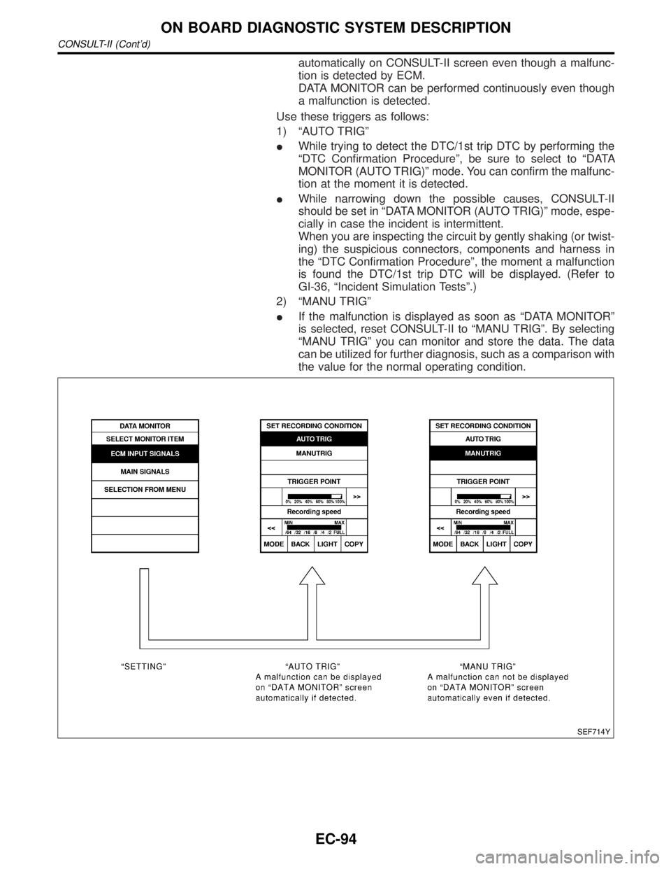
NBEC0034S10CONSULT-II has two kinds of triggers and they can be selected by
touching ªSETTINGº in ªDATA MONITORº mode.
1) ªAUTO TRIGº (Automatic trigger):
IThe malfunction will be identified on the CONSULT-II screen in
real time.
In other words, DTC/1st trip DTC and malfunction item will be
displayed if the malfunction is detected by ECM.
At the moment a malfunction is detected by ECM, ªMONITORº
in ªDATA MONITORº screen is changed to ªRecording Data ...
xx%º as shown at left, and the data after the malfunction detec-
tion is recorded. Then when the percentage reached 100%,
ªREAL-TIME DIAGº screen is displayed. If ªSTOPº is touched
on the screen during ª Recording Data ... xx%º, ªREAL-TIME
DIAGº screen is also displayed.
The recording time after the malfunction detection and the
recording speed can be changed by ªTRIGGER POINTº and
ªRecording Speedº. Refer to CONSULT-II OPERATION
MANUAL.
2) ªMANU TRIGº (Manual trigger):
IDTC/1st trip DTC and malfunction item will not be displayed
GI
MA
EM
LC
FE
AT
TF
PD
AX
SU
BR
ST
RS
BT
HA
SC
EL
IDX
ON BOARD DIAGNOSTIC SYSTEM DESCRIPTION
CONSULT-II (Cont'd)
EC-93
Page 629 of 2395

automatically on CONSULT-II screen even though a malfunc-
tion is detected by ECM.
DATA MONITOR can be performed continuously even though
a malfunction is detected.
Use these triggers as follows:
1) ªAUTO TRIGº
IWhile trying to detect the DTC/1st trip DTC by performing the
ªDTC Confirmation Procedureº, be sure to select to ªDATA
MONITOR (AUTO TRIG)º mode. You can confirm the malfunc-
tion at the moment it is detected.
IWhile narrowing down the possible causes, CONSULT-II
should be set in ªDATA MONITOR (AUTO TRIG)º mode, espe-
cially in case the incident is intermittent.
When you are inspecting the circuit by gently shaking (or twist-
ing) the suspicious connectors, components and harness in
the ªDTC Confirmation Procedureº, the moment a malfunction
is found the DTC/1st trip DTC will be displayed. (Refer to
GI-36, ªIncident Simulation Testsº.)
2) ªMANU TRIGº
IIf the malfunction is displayed as soon as ªDATA MONITORº
is selected, reset CONSULT-II to ªMANU TRIGº. By selecting
ªMANU TRIGº you can monitor and store the data. The data
can be utilized for further diagnosis, such as a comparison with
the value for the normal operating condition.
SEF714Y
ON BOARD DIAGNOSTIC SYSTEM DESCRIPTION
CONSULT-II (Cont'd)
EC-94
Page 632 of 2395

MEF036D
IntroductionNBEC0036
SEF233G
SEF234G
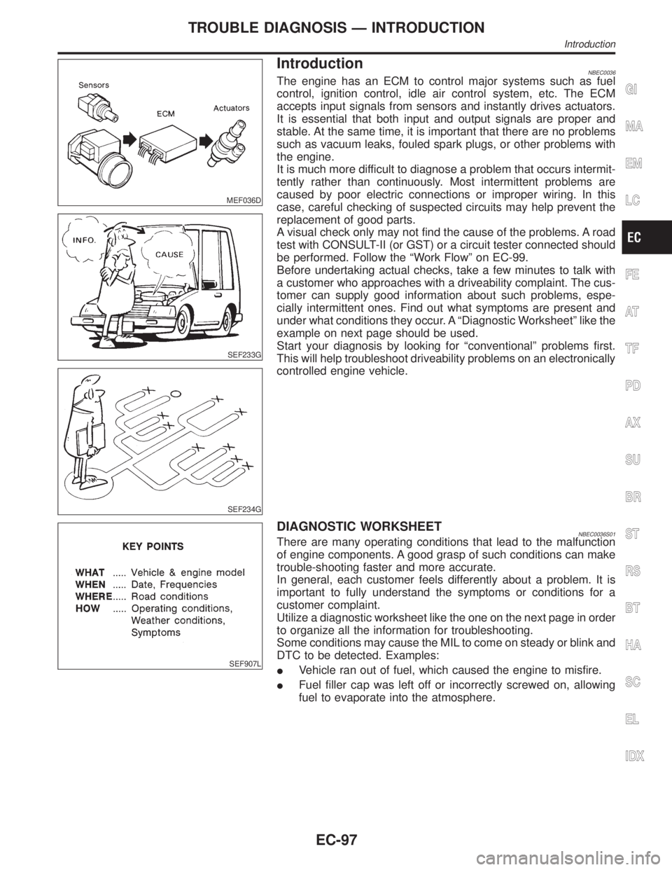
The engine has an ECM to control major systems such as fuel
control, ignition control, idle air control system, etc. The ECM
accepts input signals from sensors and instantly drives actuators.
It is essential that both input and output signals are proper and
stable. At the same time, it is important that there are no problems
such as vacuum leaks, fouled spark plugs, or other problems with
the engine.
It is much more difficult to diagnose a problem that occurs intermit-
tently rather than continuously. Most intermittent problems are
caused by poor electric connections or improper wiring. In this
case, careful checking of suspected circuits may help prevent the
replacement of good parts.
A visual check only may not find the cause of the problems. A road
test with CONSULT-II (or GST) or a circuit tester connected should
be performed. Follow the ªWork Flowº on EC-99.
Before undertaking actual checks, take a few minutes to talk with
a customer who approaches with a driveability complaint. The cus-
tomer can supply good information about such problems, espe-
cially intermittent ones. Find out what symptoms are present and
under what conditions they occur. A ªDiagnostic Worksheetº like the
example on next page should be used.
Start your diagnosis by looking for ªconventionalº problems first.
This will help troubleshoot driveability problems on an electronically
controlled engine vehicle.
SEF907L
DIAGNOSTIC WORKSHEETNBEC0036S01There are many operating conditions that lead to the malfunction
of engine components. A good grasp of such conditions can make
trouble-shooting faster and more accurate.
In general, each customer feels differently about a problem. It is
important to fully understand the symptoms or conditions for a
customer complaint.
Utilize a diagnostic worksheet like the one on the next page in order
to organize all the information for troubleshooting.
Some conditions may cause the MIL to come on steady or blink and
DTC to be detected. Examples:
IVehicle ran out of fuel, which caused the engine to misfire.
IFuel filler cap was left off or incorrectly screwed on, allowing
fuel to evaporate into the atmosphere.
GI
MA
EM
LC
FE
AT
TF
PD
AX
SU
BR
ST
RS
BT
HA
SC
EL
IDX
TROUBLE DIAGNOSIS Ð INTRODUCTION
Introduction
EC-97
Page 636 of 2395

Basic InspectionNBEC0038Precaution:
Perform Basic Inspection without electrical or mechanical
loads applied;
IHeadlamp switch is OFF,
IAir conditioner switch is OFF,
IRear window defogger switch is OFF,
ISteering wheel is in the straight-ahead position, etc.
1 INSPECTION START
1. Check service records for any recent repairs that may indicate a related problem, or a current need for scheduled
maintenance.
2. Open engine hood and check the following:
IHarness connectors for improper connections
IVacuum hoses for splits, kinks and improper connections
IWiring for improper connections, pinches and cuts
IAir cleaner clogging
IHoses and ducts for leaks
SEF983U
©GO TO 2.
2 CHECK THROTTLE OPENER OPERATION-I
Confirm that there is a clearance between throttle drum and stopper.
SEF950Y
OK or NG
OK©GO TO 4.
NG©GO TO 3.
GI
MA
EM
LC
FE
AT
TF
PD
AX
SU
BR
ST
RS
BT
HA
SC
EL
IDX
TROUBLE DIAGNOSIS Ð BASIC INSPECTION
Basic Inspection
EC-101
Page 640 of 2395

11 CHECK THROTTLE POSITION SWITCH CLOSED POSITION-II
With CONSULT-II
1. Turn ignition switch ªONº.
2. Select ªTP SW/TP SEN IDLE POSI ADJº in ªWORK SUPPORTº mode with CONSULT-II.
3. Read ªCLSD THL/P SWº signal under the following conditions.
IInsert a 0.05 mm (0.0020 in) and 0.15 mm (0.0059 in) feeler gauge alternately between stopper and throttle drum as
shown in the figure and check the signal.
SEF953Y
SEF987Y
ªCLSD THL/P SWº signal should remain ªONº while inserting 0.05 mm (0.0020 in) feeler gauge.
ªCLSD THL/P SWº signal should remain ªOFFº while inserting 0.15 mm (0.0059 in) feeler gauge.
OK or NG
OK©GO TO 14.
NG©GO TO 12.
GI
MA
EM
LC
FE
AT
TF
PD
AX
SU
BR
ST
RS
BT
HA
SC
EL
IDX
TROUBLE DIAGNOSIS Ð BASIC INSPECTION
Basic Inspection (Cont'd)
EC-105
Page 643 of 2395

14 RESET THROTTLE POSITION SENSOR IDLE POSITION MEMORY
With CONSULT-II
NOTE:
Always warm up engine to normal operating temperature. If engine is cool, the throttle position sensor idle posi-
tion memory will not be reset correctly.
1. Confirm that proper vacuum is applied. Refer to Test No. 10.
2. Attach blind cap to vacuum port from which vacuum hose to throttle opener was disconnected.
3. Start engine.
4. Warm up engine to normal operating temperature.
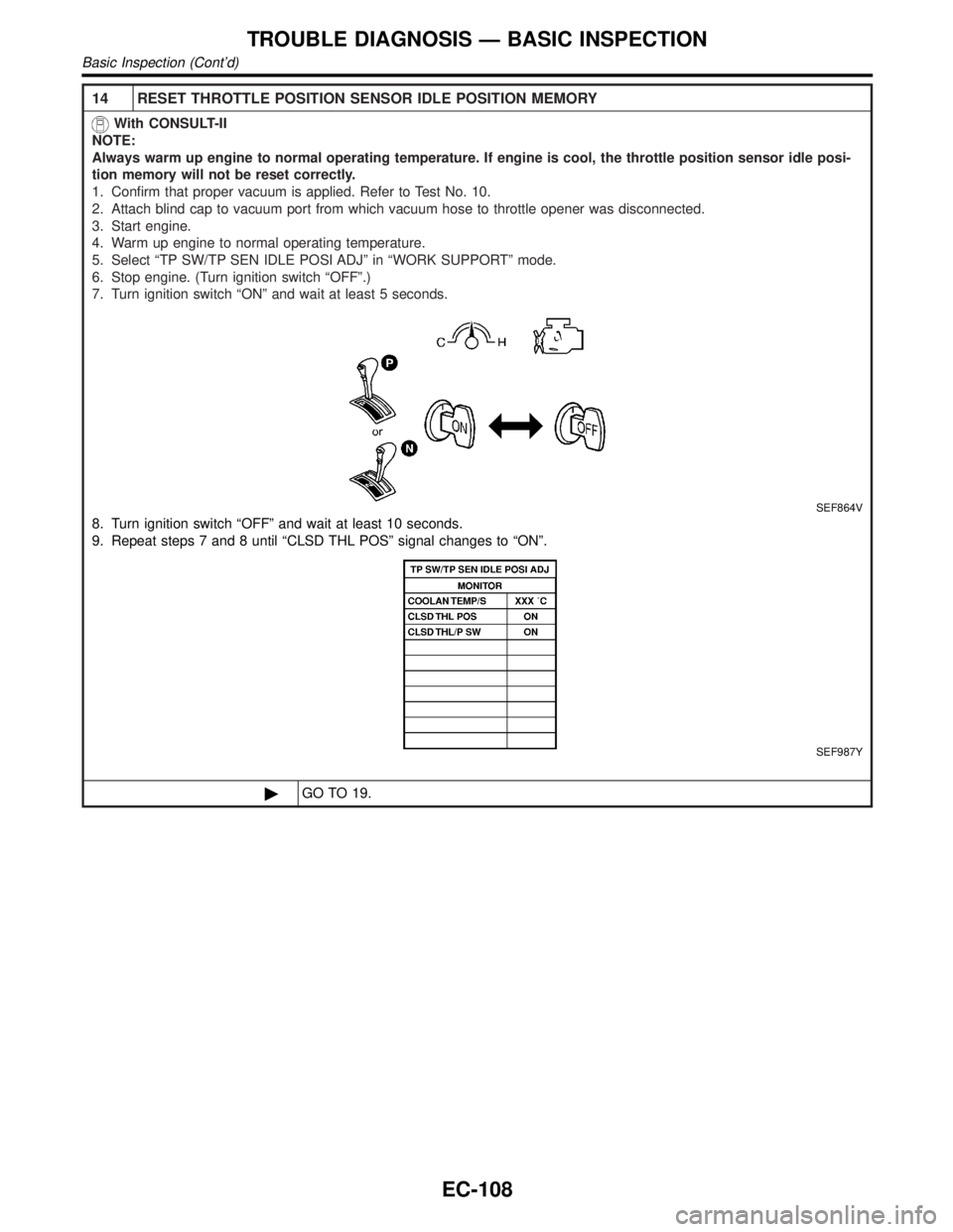
5. Select ªTP SW/TP SEN IDLE POSI ADJº in ªWORK SUPPORTº mode.
6. Stop engine. (Turn ignition switch ªOFFº.)
7. Turn ignition switch ªONº and wait at least 5 seconds.
SEF864V
8. Turn ignition switch ªOFFº and wait at least 10 seconds.
9. Repeat steps 7 and 8 until ªCLSD THL POSº signal changes to ªONº.
SEF987Y
©GO TO 19.
TROUBLE DIAGNOSIS Ð BASIC INSPECTION
Basic Inspection (Cont'd)
EC-108