Ac system INFINITI QX4 2001 Factory Service Manual
[x] Cancel search | Manufacturer: INFINITI, Model Year: 2001, Model line: QX4, Model: INFINITI QX4 2001Pages: 2395, PDF Size: 43.2 MB
Page 651 of 2395

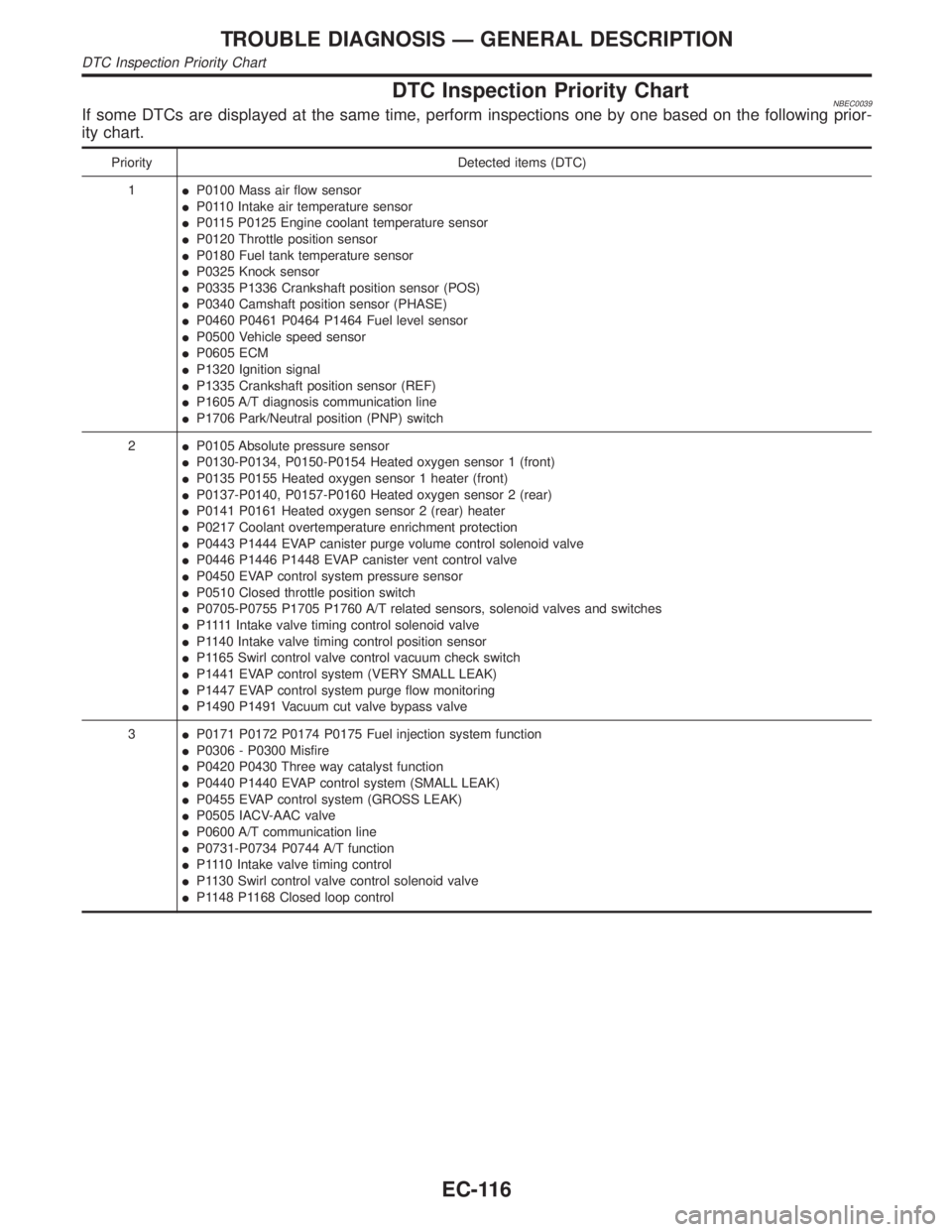
DTC Inspection Priority ChartNBEC0039If some DTCs are displayed at the same time, perform inspections one by one based on the following prior-
ity chart.
Priority Detected items (DTC)
1IP0100 Mass air flow sensor
IP0110 Intake air temperature sensor
IP0115 P0125 Engine coolant temperature sensor
IP0120 Throttle position sensor
IP0180 Fuel tank temperature sensor
IP0325 Knock sensor
IP0335 P1336 Crankshaft position sensor (POS)
IP0340 Camshaft position sensor (PHASE)
IP0460 P0461 P0464 P1464 Fuel level sensor
IP0500 Vehicle speed sensor
IP0605 ECM
IP1320 Ignition signal
IP1335 Crankshaft position sensor (REF)
IP1605 A/T diagnosis communication line
IP1706 Park/Neutral position (PNP) switch
2IP0105 Absolute pressure sensor
IP0130-P0134, P0150-P0154 Heated oxygen sensor 1 (front)
IP0135 P0155 Heated oxygen sensor 1 heater (front)
IP0137-P0140, P0157-P0160 Heated oxygen sensor 2 (rear)
IP0141 P0161 Heated oxygen sensor 2 (rear) heater
IP0217 Coolant overtemperature enrichment protection
IP0443 P1444 EVAP canister purge volume control solenoid valve
IP0446 P1446 P1448 EVAP canister vent control valve
IP0450 EVAP control system pressure sensor
IP0510 Closed throttle position switch
IP0705-P0755 P1705 P1760 A/T related sensors, solenoid valves and switches
IP 1111Intake valve timing control solenoid valve
IP1140 Intake valve timing control position sensor
IP1165 Swirl control valve control vacuum check switch
IP1441 EVAP control system (VERY SMALL LEAK)
IP1447 EVAP control system purge flow monitoring
IP1490 P1491 Vacuum cut valve bypass valve
3IP0171 P0172 P0174 P0175 Fuel injection system function
IP0306 - P0300 Misfire
IP0420 P0430 Three way catalyst function
IP0440 P1440 EVAP control system (SMALL LEAK)
IP0455 EVAP control system (GROSS LEAK)
IP0505 IACV-AAC valve
IP0600 A/T communication line
IP0731-P0734 P0744 A/T function
IP1110 Intake valve timing control
IP1130 Swirl control valve control solenoid valve
IP1148 P1168 Closed loop control
TROUBLE DIAGNOSIS Ð GENERAL DESCRIPTION
DTC Inspection Priority Chart
EC-116
Page 652 of 2395

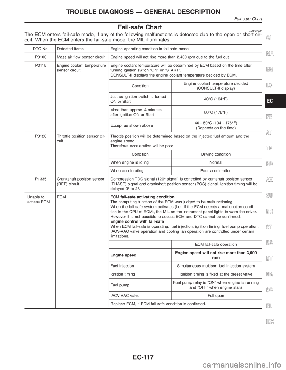
Fail-safe Chart=NBEC0040The ECM enters fail-safe mode, if any of the following malfunctions is detected due to the open or short cir-
cuit. When the ECM enters the fail-safe mode, the MIL illuminates.
DTC No. Detected items Engine operating condition in fail-safe mode
P0100 Mass air flow sensor circuit Engine speed will not rise more than 2,400 rpm due to the fuel cut.
P0115 Engine coolant temperature
sensor circuitEngine coolant temperature will be determined by ECM based on the time after
turning ignition switch ªONº or ªSTARTº.
CONSULT-II displays the engine coolant temperature decided by ECM.
ConditionEngine coolant temperature decided
(CONSULT-II display)
Just as ignition switch is turned
ON or Start40ÉC (104ÉF)
More than approx. 4 minutes
after ignition ON or Start80ÉC (176ÉF)
Except as shown above40 - 80ÉC (104 - 176ÉF)
(Depends on the time)
P0120 Throttle position sensor cir-
cuitThrottle position will be determined based on the injected fuel amount and the
engine speed.
Therefore, acceleration will be poor.
Condition Driving condition
When engine is idling Normal
When accelerating Poor acceleration
P1335 Crankshaft position sensor
(REF) circuitCompression TDC signal (120É signal) is controlled by camshaft position sensor
(PHASE) signal and crankshaft position sensor (POS) signal. Ignition timing will be
delayed 0É to 2É.
Unable to
access ECMECMECM fail-safe activating condition
The computing function of the ECM was judged to be malfunctioning.
When the fail-safe system activates (i.e., if the ECM detects a malfunction condi-
tion in the CPU of ECM), the MIL on the instrument panel lights to warn the driver.
However it is not possible to access ECM and DTC cannot be confirmed.
Engine control with fail-safe
When ECM fail-safe is operating, fuel injection, ignition timing, fuel pump operation,
IACV-AAC valve operation and cooling fan operation are controlled under certain
limitations.
ECM fail-safe operation
Engine speedEngine speed will not rise more than 3,000
rpm
Fuel injection Simultaneous multiport fuel injection system
Ignition timing Ignition timing is fixed at the preset valve
Fuel pumpFuel pump relay is ªONº when engine is running
and ªOFFº when engine stalls
IACV-AAC valve Full open
Replace ECM, if ECM fail-safe condition is confirmed.
GI
MA
EM
LC
FE
AT
TF
PD
AX
SU
BR
ST
RS
BT
HA
SC
EL
IDX
TROUBLE DIAGNOSIS Ð GENERAL DESCRIPTION
Fail-safe Chart
EC-117
Page 653 of 2395

Symptom Matrix ChartNBEC0041SYSTEM Ð BASIC ENGINE CONTROL SYSTEMNBEC0041S01
SYMPTOM
Reference
page
HARD/NO START/RESTART (EXCP. HA)
ENGINE STALL
HESITATION/SURGING/FLAT SPOT
SPARK KNOCK/DETONATION
LACK OF POWER/POOR ACCELERATION
HIGH IDLE/LOW IDLE
ROUGH IDLE/HUNTING
IDLING VIBRATION
SLOW/NO RETURN TO IDLE
OVERHEATS/WATER TEMPERATURE HIGH
EXCESSIVE FUEL CONSUMPTION
EXCESSIVE OIL CONSUMPTION
BATTERY DEAD (UNDER CHARGE)
Warranty symptom code AA AB AC AD AE AF AG AH AJ AK AL AM HA
Fuel Fuel pump circuit11232 2 2 3 2EC-625
Fuel pressure regulator system3344444 4 4 4EC-40
Injector circuit11232 2 2 2EC-616
Evaporative emission system
3344444 4 4 4EC-32
Air Positive crankcase ventilation sys-
tem1 EC-38
Incorrect idle speed adjustment 1 1 1 1 1 EC-101
IACV-AAC valve circuit1123322 2 2 2 2EC-422
Ignition Incorrect ignition timing adjustment33111 1 1 1EC-101
Ignition circuit 1 1 2 2 2 2 2 2 EC-499
Main power supply and ground circuit
22333 3 32
3EC-142
Air conditioner circuit 3 3 2 HA section
1 - 6: The numbers refer to the order of inspection.
(continued on next page)
TROUBLE DIAGNOSIS Ð GENERAL DESCRIPTION
Symptom Matrix Chart
EC-118
Page 655 of 2395

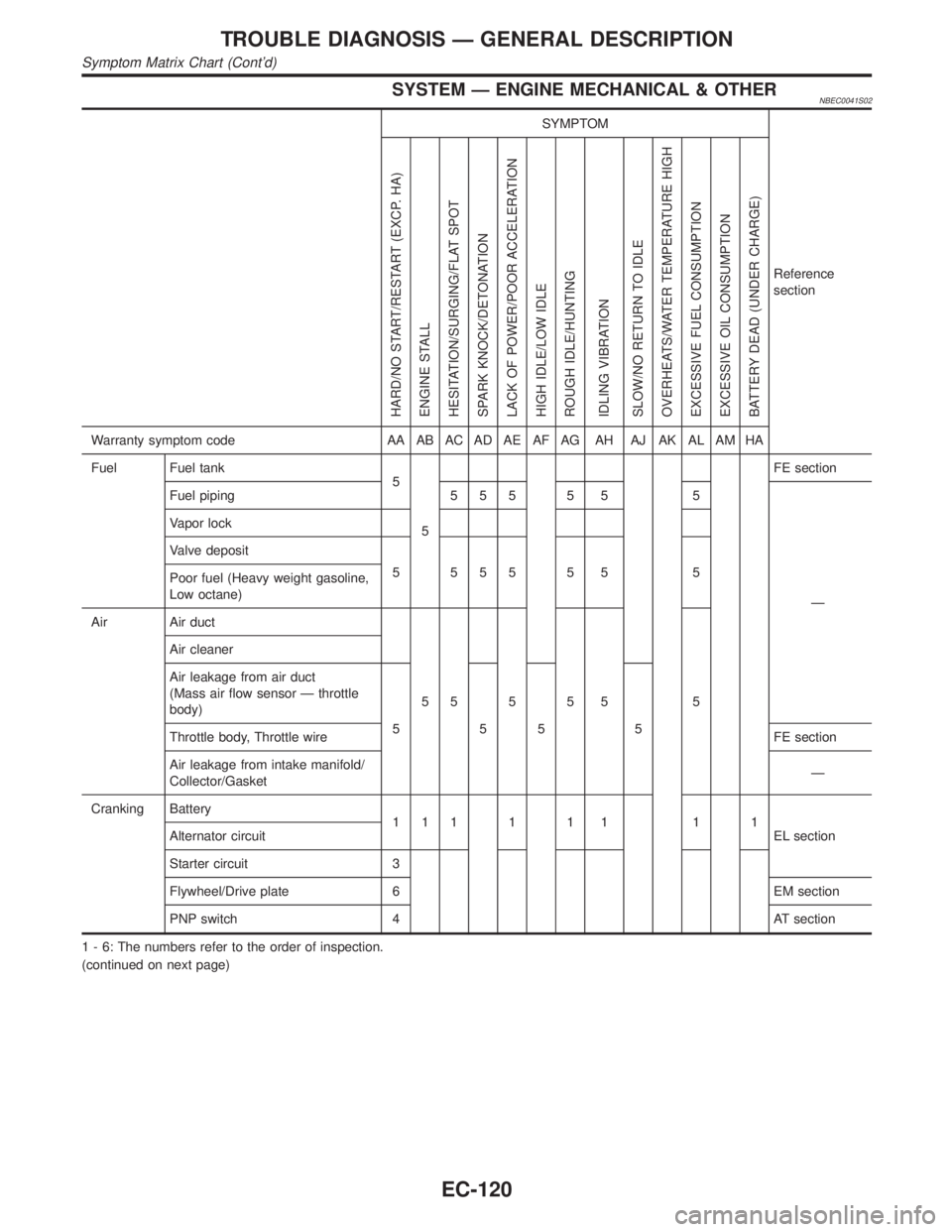
SYSTEM Ð ENGINE MECHANICAL & OTHERNBEC0041S02
SYMPTOM
Reference
section
HARD/NO START/RESTART (EXCP. HA)
ENGINE STALL
HESITATION/SURGING/FLAT SPOT
SPARK KNOCK/DETONATION
LACK OF POWER/POOR ACCELERATION
HIGH IDLE/LOW IDLE
ROUGH IDLE/HUNTING
IDLING VIBRATION
SLOW/NO RETURN TO IDLE
OVERHEATS/WATER TEMPERATURE HIGH
EXCESSIVE FUEL CONSUMPTION
EXCESSIVE OIL CONSUMPTION
BATTERY DEAD (UNDER CHARGE)
Warranty symptom code AA AB AC AD AE AF AG AH AJ AK AL AM HA
Fuel Fuel tank
5
5FE section
Fuel piping 5 5 5 5 5 5
Ð Vapor lock
Valve deposit
5 555 5 5 5
Poor fuel (Heavy weight gasoline,
Low octane)
Air Air duct
55555 5 Air cleaner
Air leakage from air duct
(Mass air flow sensor Ð throttle
body)
555 5
Throttle body, Throttle wireFE section
Air leakage from intake manifold/
Collector/GasketÐ
Cranking Battery
111111 11
EL section Alternator circuit
Starter circuit 3
Flywheel/Drive plate 6 EM section
PNP switch 4 AT section
1 - 6: The numbers refer to the order of inspection.
(continued on next page)
TROUBLE DIAGNOSIS Ð GENERAL DESCRIPTION
Symptom Matrix Chart (Cont'd)
EC-120
Page 657 of 2395

SYMPTOM
Reference
section
HARD/NO START/RESTART (EXCP. HA)
ENGINE STALL
HESITATION/SURGING/FLAT SPOT
SPARK KNOCK/DETONATION
LACK OF POWER/POOR ACCELERATION
HIGH IDLE/LOW IDLE
ROUGH IDLE/HUNTING
IDLING VIBRATION
SLOW/NO RETURN TO IDLE
OVERHEATS/WATER TEMPERATURE HIGH
EXCESSIVE FUEL CONSUMPTION
EXCESSIVE OIL CONSUMPTION
BATTERY DEAD (UNDER CHARGE)
Warranty symptom code AA AB AC AD AE AF AG AH AJ AK AL AM HA
IVIS (INFINITI Vehicle Immobilizer System Ð
NATS)11EC-74 or EL
section
1 - 6: The numbers refer to the order of inspection.
CONSULT-II Reference Value in Data Monitor
Mode
NBEC0042Remarks:
ISpecification data are reference values.
ISpecification data are output/input values which are detected or supplied by the ECM at the connector.
* Specification data may not be directly related to their components signals/values/operations.
i.e. Adjust ignition timing with a timing light before monitoring IGN TIMING, because the monitor may show the specification data in
spite of the ignition timing not being adjusted to the specification data. This IGN TIMING monitors the data calculated by the ECM
according to the signals input from the camshaft position sensor and other ignition timing related sensors.
IIf the real-time diagnosis results are NG and the on board diagnostic system results are OK when diagnosing the mass air flow sensor,
first check to see if the fuel pump control circuit is normal.
MONITOR ITEM CONDITION SPECIFICATION
ENG SPEED
CKPS´RPM (POS)ITachometer: Connect
IRun engine and compare tachometer indication with the CONSULT-II
value.Almost the same speed as
the CONSULT-II value.
POS COUNTIEngine: Running 179 - 181
MAS A/F SE-B1IEngine: After warming up
IAir conditioner switch: ªOFFº
IShift lever: ªNº
INo-loadIdle 1.2 - 1.8V
2,500 rpm 1.6 - 2.2V
COOLAN TEMP/SIEngine: After warming up More than 70ÉC (158ÉF)
HO2S1 (B1)
HO2S1 (B2)
IEngine: After warming upMaintaining engine speed at 2,000
rpm0 - 0.3V+,Approx. 0.6 -
1.0V
HO2S1 MNTR (B1)
HO2S1 MNTR (B2)LEAN+,RICH
Changes more than 5 times
during 10 seconds.
HO2S2 (B1)
HO2S2 (B2)
IEngine: After warming upMaintaining engine speed at 2,000
rpm0 - 0.3V+,Approx. 0.6 -
1.0V
HO2S2 MNTR (B1)
HO2S2 MNTR (B2)LEAN+,RICH
TROUBLE DIAGNOSIS Ð GENERAL DESCRIPTION
Symptom Matrix Chart (Cont'd)
EC-122
Page 668 of 2395
![INFINITI QX4 2001 Factory Service Manual TERMI-
NAL
NO.WIRE
COLORITEM CONDITION DATA (DC Voltage)
71 OR/LHeated oxygen sensor
2 (rear) (bank 2)[Engine is running]
IWarm-up condition
IEngine speed is 2,000 rpm.0 - Approximately 1.0V
72 ORHeat INFINITI QX4 2001 Factory Service Manual TERMI-
NAL
NO.WIRE
COLORITEM CONDITION DATA (DC Voltage)
71 OR/LHeated oxygen sensor
2 (rear) (bank 2)[Engine is running]
IWarm-up condition
IEngine speed is 2,000 rpm.0 - Approximately 1.0V
72 ORHeat](/img/42/57027/w960_57027-667.png)
TERMI-
NAL
NO.WIRE
COLORITEM CONDITION DATA (DC Voltage)
71 OR/LHeated oxygen sensor
2 (rear) (bank 2)[Engine is running]
IWarm-up condition
IEngine speed is 2,000 rpm.0 - Approximately 1.0V
72 ORHeated oxygen sensor
2 (rear) (bank 1)[Engine is running]
IWarm-up condition
IEngine speed is 2,000 rpm.0 - Approximately 1.0V
73 B/PMass air flow sensor
ground[Engine is running]
IWarm-up condition
IIdle speedApproximately 0V
79 Y/GIntake valve timing
control position sen-
sors (RH)[Engine is running]
IWarm-up condition
IIdle speedApproximately 0.5V
SEF351Z
[Engine is running]
IWarm-up condition
IEngine speed is 2,000 rpm.Approximatley 0.5V
SEF352Z
80 L/RAbsolute pressure sen-
sor[Ignition switch ªONº]Approximately 4.4V
81 W/PURefrigerant pressure
sensor[Engine is running]
IWarm-up condition
IBoth A/C switch and blower switch are ªONº.
(Compressor operates.)0.36 - 3.88V
82 WThrottle position sensor
signal output[Engine is running]
IWarm-up condition
IAccelerator pedal fully releasedApproximately 0.4V
[Ignition switch ªONº]
IAccelerator pedal fully depressedApproximately 4V
83 Y/PU Fuel level sensor[Ignition switch ªONº]Approximately 0 - 4.8V
Output voltage varies with
fuel level.
84 L/GEVAP control system
pressure sensor[Ignition switch ªONº]Approximately 3.4V
GI
MA
EM
LC
FE
AT
TF
PD
AX
SU
BR
ST
RS
BT
HA
SC
EL
IDX
TROUBLE DIAGNOSIS Ð GENERAL DESCRIPTION
ECM Terminals and Reference Value (Cont'd)
EC-133
Page 671 of 2395

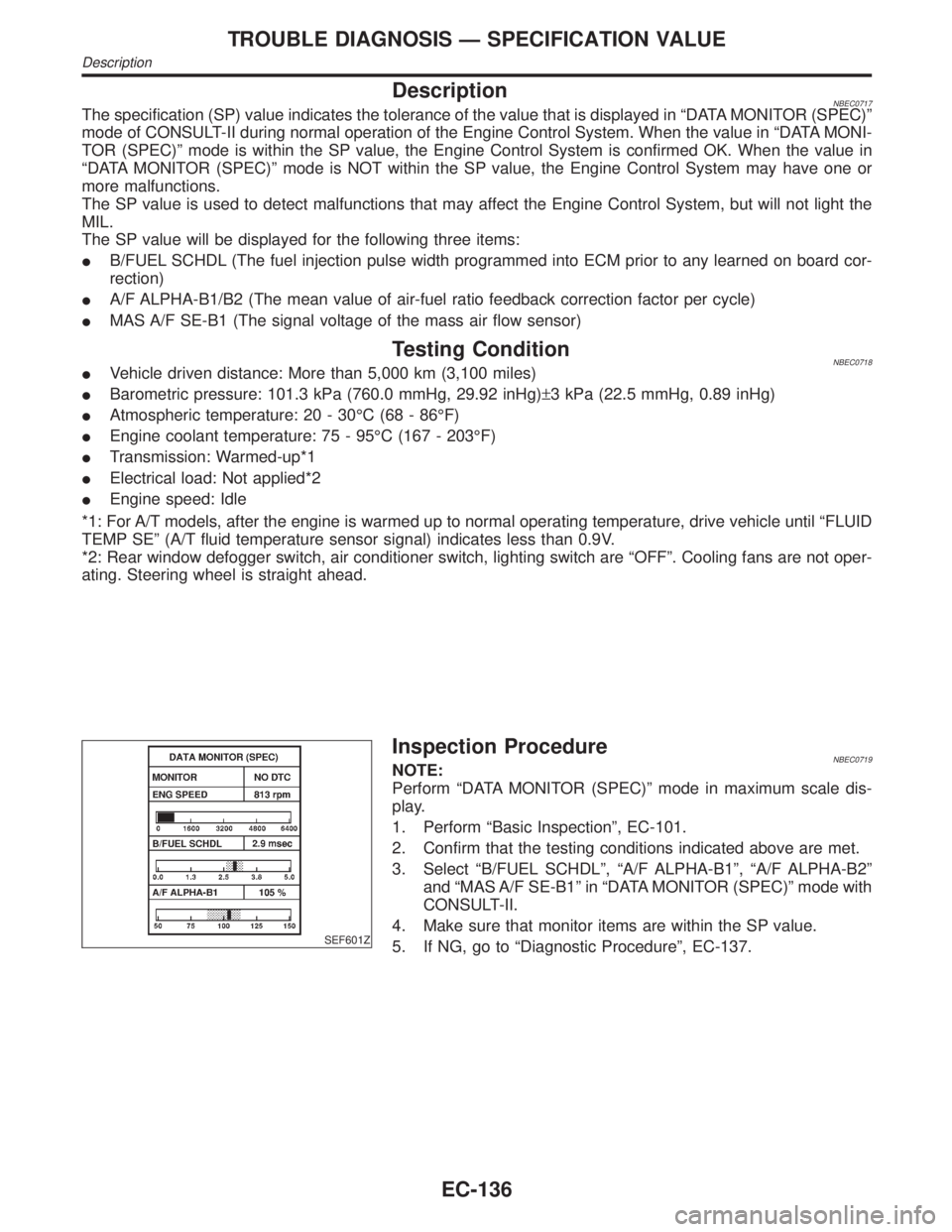
DescriptionNBEC0717The specification (SP) value indicates the tolerance of the value that is displayed in ªDATA MONITOR (SPEC)º
mode of CONSULT-II during normal operation of the Engine Control System. When the value in ªDATA MONI-
TOR (SPEC)º mode is within the SP value, the Engine Control System is confirmed OK. When the value in
ªDATA MONITOR (SPEC)º mode is NOT within the SP value, the Engine Control System may have one or
more malfunctions.
The SP value is used to detect malfunctions that may affect the Engine Control System, but will not light the
MIL.
The SP value will be displayed for the following three items:
IB/FUEL SCHDL (The fuel injection pulse width programmed into ECM prior to any learned on board cor-
rection)
IA/F ALPHA-B1/B2 (The mean value of air-fuel ratio feedback correction factor per cycle)
IMAS A/F SE-B1 (The signal voltage of the mass air flow sensor)
Testing ConditionNBEC0718IVehicle driven distance: More than 5,000 km (3,100 miles)
IBarometric pressure: 101.3 kPa (760.0 mmHg, 29.92 inHg)±3 kPa (22.5 mmHg, 0.89 inHg)
IAtmospheric temperature: 20 - 30ÉC (68 - 86ÉF)
IEngine coolant temperature: 75 - 95ÉC (167 - 203ÉF)
ITransmission: Warmed-up*1
IElectrical load: Not applied*2
IEngine speed: Idle
*1: For A/T models, after the engine is warmed up to normal operating temperature, drive vehicle until ªFLUID
TEMP SEº (A/T fluid temperature sensor signal) indicates less than 0.9V.
*2: Rear window defogger switch, air conditioner switch, lighting switch are ªOFFº. Cooling fans are not oper-
ating. Steering wheel is straight ahead.
SEF601Z
Inspection ProcedureNBEC0719NOTE:
Perform ªDATA MONITOR (SPEC)º mode in maximum scale dis-
play.
1. Perform ªBasic Inspectionº, EC-101.
2. Confirm that the testing conditions indicated above are met.
3. Select ªB/FUEL SCHDLº, ªA/F ALPHA-B1º, ªA/F ALPHA-B2º
and ªMAS A/F SE-B1º in ªDATA MONITOR (SPEC)º mode with
CONSULT-II.
4. Make sure that monitor items are within the SP value.
5. If NG, go to ªDiagnostic Procedureº, EC-137.
TROUBLE DIAGNOSIS Ð SPECIFICATION VALUE
Description
EC-136
Page 690 of 2395

Diagnostic ProcedureNBEC0057
1 INSPECTION START
Which malfunction (A, B, C, D or E) is duplicated?
MTBL0373
Type I or Type II
Type I©GO TO 3.
Type II©GO TO 2.
2 CHECK INTAKE SYSTEM
Check the following for connection.
IAir duct
IVacuum hoses
IIntake air passage between air duct to intake manifold collector
OK or NG
OK©GO TO 3.
NG©Reconnect the parts.
3 RETIGHTEN GROUND SCREWS
1. Turn ignition switch ªOFFº.
2. Loosen and retighten engine ground screws.
SEF959Y
©GO TO 4.
GI
MA
EM
LC
FE
AT
TF
PD
AX
SU
BR
ST
RS
BT
HA
SC
EL
IDX
DTC P0100 MASS AIR FLOW SENSOR (MAFS)
Diagnostic Procedure
EC-155
Page 716 of 2395

Diagnostic ProcedureNBEC0080
1 INSPECTION START
Which malfunction A, B or C is duplicated?
MTBL0066
TypeA,BorC
TypeAor B©GO TO 4.
Type C©GO TO 2.
2 ADJUST THROTTLE POSITION SENSOR
Check the following items. Refer to ªBasic Inspectionº, EC-101.
MTBL0655
©GO TO 3.
3 CHECK INTAKE SYSTEM.
1. Turn ignition switch ªOFFº.
2. Check the following for connection.
IAir duct
IVacuum hoses
IIntake air passage between air duct to intake manifold collector
OK or NG
OK©GO TO 4.
NG©Reconnect the parts.
4 RETIGHTEN GROUND SCREWS
1. Turn ignition switch ªOFFº.
2. Loosen and retighten engine ground screws.
SEF959Y
©GO TO 5.
GI
MA
EM
LC
FE
AT
TF
PD
AX
SU
BR
ST
RS
BT
HA
SC
EL
IDX
DTC P0120 THROTTLE POSITION SENSOR
Diagnostic Procedure
EC-181
Page 736 of 2395

4 CHECK HEATED OXYGEN SENSOR 1 (FRONT)
Without CONSULT-II
1. Start engine and warm it up to normal operating temperature.
2. Set voltmeter probes between ECM terminal 63 (HO2S1 bank 1 right signal) or 62 (HO2S1 bank 2 left signal) and
engine ground.
3. Check the following with engine speed held at 2,000 rpm constant under no load.
SEF967XA
CAUTION:
Discard any heated oxygen sensor which has been dropped from a height of more than 0.5 m (19.7 in) onto a
hard surface such as a concrete floor; use a new one.
OK or NG
OK©GO TO 6.
NG©GO TO 5.
5 REPLACE HEATED OXYGEN SENSOR 1 (FRONT)
1. Turn ignition switch ªOFFº.
2. Check heated oxygen sensor 1 (front) harness protector color.
SEF505Y
CAUTION:
Before installing new oxygen sensor, clean exhaust system threads using Oxygen Sensor Thread Cleaner tool
J-43897-18 or J-43897-12 and approved anti-seize lubricant.
©Replace malfunctioning heated oxygen sensor 1 (front).
6 CHECK INTERMITTENT INCIDENT
Refer to ªTROUBLE DIAGNOSIS FOR INTERMITTENT INCIDENTº, EC-140.
©INSPECTION END
GI
MA
EM
LC
FE
AT
TF
PD
AX
SU
BR
ST
RS
BT
HA
SC
EL
IDX
DTC P0130, P0150 HEATED OXYGEN SENSOR 1 (FRONT) (BANK 1)/(BANK 2)
(CIRCUIT)
Diagnostic Procedure (Cont'd)
EC-201