Ac system INFINITI QX4 2001 Factory Service Manual
[x] Cancel search | Manufacturer: INFINITI, Model Year: 2001, Model line: QX4, Model: INFINITI QX4 2001Pages: 2395, PDF Size: 43.2 MB
Page 838 of 2395

SEF960Y
WITH GSTNBEC0174S021) Start engine and warm it up to normal operating temperature.
2) Turn ignition switch ªOFFº and wait at least 10 seconds.
3) Disconnect mass air flow sensor harness connector. Then
restart and run engine for at least 5 seconds at idle speed.
4) Stop engine and reconnect mass air flow sensor harness con-
nector.
5) Select ªMODE 7º with GST. Make sure 1st trip DTC P0100 is
detected.
6) Select ªMODE 4º with GST and erase the 1st trip DTC P0100.
7) Start engine again and let it idle for at least 10 minutes.
8) Select ªMODE 7º with GST. The 1st trip DTC P0172 or P0175
should be detected at this stage, if a malfunction exists. If so,
go to ªDiagnostic Procedureº, EC-306.
9) If it is difficult to start engine at step 7, the fuel injection sys-
tem has a malfunction.
10) Crank engine while depressing accelerator pedal.
If engine starts, go to ªDiagnostic Procedureº, EC-306. If
engine does not start, check exhaust and intake air leak visu-
ally.
GI
MA
EM
LC
FE
AT
TF
PD
AX
SU
BR
ST
RS
BT
HA
SC
EL
IDX
DTC P0172 (RIGHT, -B1), P0175 (LEFT, -B2) FUEL INJECTION SYSTEM
FUNCTION (RICH)
DTC Confirmation Procedure (Cont'd)
EC-303
Page 839 of 2395

Wiring DiagramNBEC0175RIGHT BANKNBEC0175S01
MEC955C
DTC P0172 (RIGHT, -B1), P0175 (LEFT, -B2) FUEL INJECTION SYSTEM
FUNCTION (RICH)
Wiring Diagram
EC-304
Page 840 of 2395

LEFT BANKNBEC0175S02
MEC956C
GI
MA
EM
LC
FE
AT
TF
PD
AX
SU
BR
ST
RS
BT
HA
SC
EL
IDX
DTC P0172 (RIGHT, -B1), P0175 (LEFT, -B2) FUEL INJECTION SYSTEM
FUNCTION (RICH)
Wiring Diagram (Cont'd)
EC-305
Page 841 of 2395
Diagnostic ProcedureNBEC0176
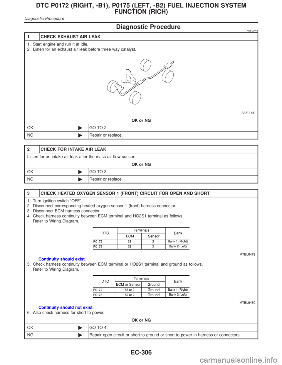
1 CHECK EXHAUST AIR LEAK
1. Start engine and run it at idle.
2. Listen for an exhaust air leak before three way catalyst.
SEF099P
OK or NG
OK©GO TO 2.
NG©Repair or replace.
2 CHECK FOR INTAKE AIR LEAK
Listen for an intake air leak after the mass air flow sensor.
OK or NG
OK©GO TO 3.
NG©Repair or replace.
3 CHECK HEATED OXYGEN SENSOR 1 (FRONT) CIRCUIT FOR OPEN AND SHORT
1. Turn ignition switch ªOFFº.
2. Disconnect corresponding heated oxygen sensor 1 (front) harness connector.
3. Disconnect ECM harness connector.
4. Check harness continuity between ECM terminal and HO2S1 terminal as follows.
Refer to Wiring Diagram.
MTBL0479
Continuity should exist.
5. Check harness continuity between ECM terminal or HO2S1 terminal and ground as follows.
Refer to Wiring Diagram.
MTBL0480
Continuity should not exist.
6. Also check harness for short to power.
OK or NG
OK©GO TO 4.
NG©Repair open circuit or short to ground or short to power in harness or connectors.
DTC P0172 (RIGHT, -B1), P0175 (LEFT, -B2) FUEL INJECTION SYSTEM
FUNCTION (RICH)
Diagnostic Procedure
EC-306
Page 842 of 2395
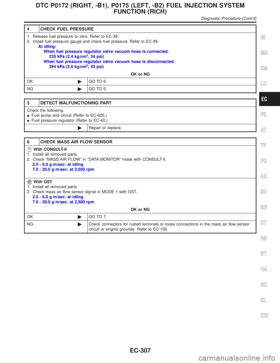
4 CHECK FUEL PRESSURE
1. Release fuel pressure to zero. Refer to EC-39.
2. Install fuel pressure gauge and check fuel pressure. Refer to EC-39.
At idling:
When fuel pressure regulator valve vacuum hose is connected.
235 kPa (2.4 kg/cm
2, 34 psi)
When fuel pressure regulator valve vacuum hose is disconnected.
294 kPa (3.0 kg/cm
2, 43 psi)
OK or NG
OK©GO TO 6.
NG©GO TO 5.
5 DETECT MALFUNCTIONING PART
Check the following.
IFuel pump and circuit (Refer to EC-625.)
IFuel pressure regulator (Refer to EC-40.)
©Repair or replace.
6 CHECK MASS AIR FLOW SENSOR
With CONSULT-II
1. Install all removed parts.
2. Check ªMASS AIR FLOWº in ªDATA MONITORº mode with CONSULT-II.
2.0 - 6.0 g´m/sec: at idling
7.0 - 20.0 g´m/sec: at 2,500 rpm
With GST
1. Install all removed parts.
2. Check mass air flow sensor signal in MODE 1 with GST.
2.0 - 6.0 g´m/sec: at idling
7.0 - 20.0 g´m/sec: at 2,500 rpm
OK or NG
OK©GO TO 7.
NG©Check connectors for rusted terminals or loose connections in the mass air flow sensor
circuit or engine grounds. Refer to EC-150.
GI
MA
EM
LC
FE
AT
TF
PD
AX
SU
BR
ST
RS
BT
HA
SC
EL
IDX
DTC P0172 (RIGHT, -B1), P0175 (LEFT, -B2) FUEL INJECTION SYSTEM
FUNCTION (RICH)
Diagnostic Procedure (Cont'd)
EC-307
Page 843 of 2395
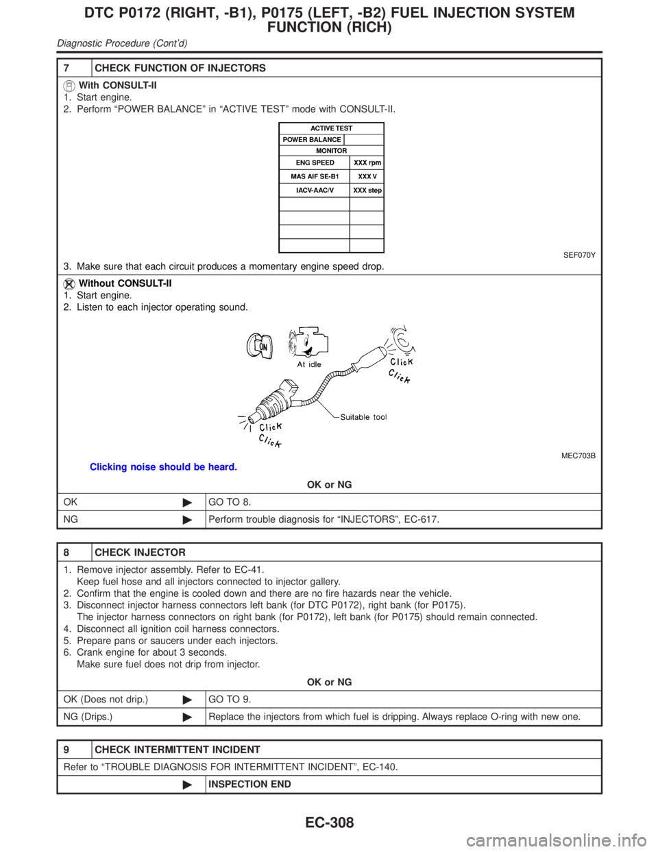
7 CHECK FUNCTION OF INJECTORS
With CONSULT-II
1. Start engine.
2. Perform ªPOWER BALANCEº in ªACTIVE TESTº mode with CONSULT-II.
SEF070Y
3. Make sure that each circuit produces a momentary engine speed drop.
Without CONSULT-II
1. Start engine.
2. Listen to each injector operating sound.
MEC703B
Clicking noise should be heard.
OK or NG
OK©GO TO 8.
NG©Perform trouble diagnosis for ªINJECTORSº, EC-617.
8 CHECK INJECTOR
1. Remove injector assembly. Refer to EC-41.
Keep fuel hose and all injectors connected to injector gallery.
2. Confirm that the engine is cooled down and there are no fire hazards near the vehicle.
3. Disconnect injector harness connectors left bank (for DTC P0172), right bank (for P0175).
The injector harness connectors on right bank (for P0172), left bank (for P0175) should remain connected.
4. Disconnect all ignition coil harness connectors.
5. Prepare pans or saucers under each injectors.
6. Crank engine for about 3 seconds.
Make sure fuel does not drip from injector.
OK or NG
OK (Does not drip.)©GO TO 9.
NG (Drips.)©Replace the injectors from which fuel is dripping. Always replace O-ring with new one.
9 CHECK INTERMITTENT INCIDENT
Refer to ªTROUBLE DIAGNOSIS FOR INTERMITTENT INCIDENTº, EC-140.
©INSPECTION END
DTC P0172 (RIGHT, -B1), P0175 (LEFT, -B2) FUEL INJECTION SYSTEM
FUNCTION (RICH)
Diagnostic Procedure (Cont'd)
EC-308
Page 851 of 2395
4) Make sure that A/C switch is ªOFFº and air conditioner is not
operating. If NG, check air conditioner circuit. Refer to HA-35
or HA-30, ªTROUBLE DIAGNOSESº. After repair, go to the
next step.
5) Check for blocked coolant passage.
a) Warm up engine to normal operating temperature, then grasp
radiator upper hose and lower hose and make sure that cool-
ant flows.
If NG, go to ªDiagnostic Procedureº, EC-316. After repair, go
to the next step.
Be extremely careful not to touch any moving or adjacent
parts.
6) Check for blocked radiator air passage.
a) When market fog lamps have been installed, check for dam-
aged fans and clogging in the condenser and radiator.
b) Check the front end for clogging caused by insects or debris.
c) Check for improper fitting of front-end cover, damaged radia-
tor grille or bumper, damaged vehicle front.
If NG, take appropriate action and then go to the next step.
7) Check function of ECT sensor.
Refer to step 6 of ªDiagnostic Procedureº, EC-316.
If NG, replace ECT sensor and go to the next step.
8) Check ignition timing. Refer to basic inspection, EC-101.
Make sure that ignition timing is 15ɱ5É at idle.
If NG, adjust ignition timing and then recheck.
Diagnostic ProcedureNBEC0614
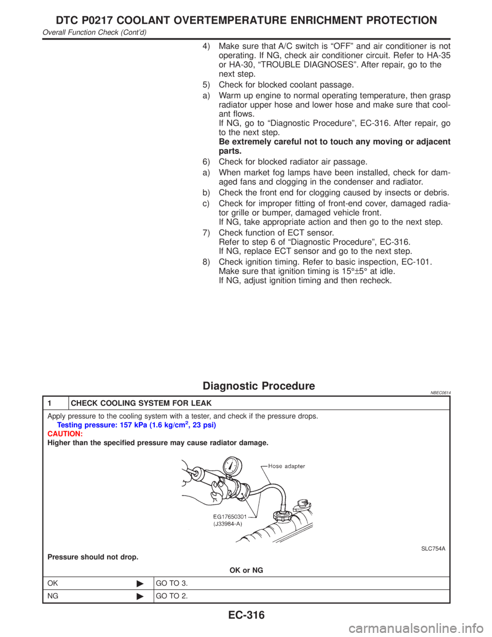
1 CHECK COOLING SYSTEM FOR LEAK
Apply pressure to the cooling system with a tester, and check if the pressure drops.
Testing pressure: 157 kPa (1.6 kg/cm2, 23 psi)
CAUTION:
Higher than the specified pressure may cause radiator damage.
SLC754A
Pressure should not drop.
OK or NG
OK©GO TO 3.
NG©GO TO 2.
DTC P0217 COOLANT OVERTEMPERATURE ENRICHMENT PROTECTION
Overall Function Check (Cont'd)
EC-316
Page 854 of 2395
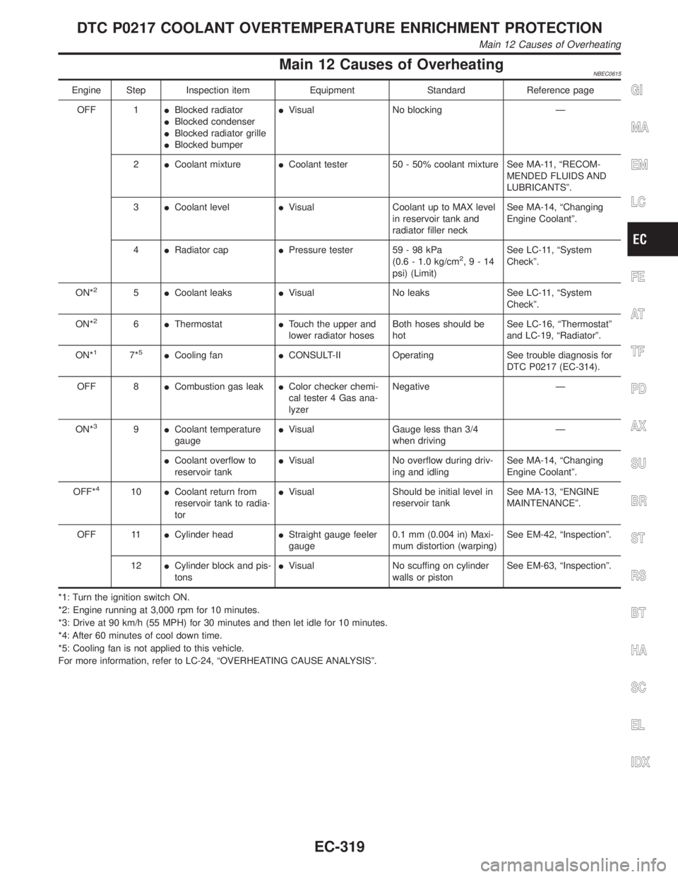
Main 12 Causes of OverheatingNBEC0615
Engine Step Inspection item Equipment Standard Reference page
OFF 1IBlocked radiator
IBlocked condenser
IBlocked radiator grille
IBlocked bumperIVisual No blocking Ð
2ICoolant mixtureICoolant tester 50 - 50% coolant mixture See MA-11, ªRECOM-
MENDED FLUIDS AND
LUBRICANTSº.
3ICoolant levelIVisual Coolant up to MAX level
in reservoir tank and
radiator filler neckSee MA-14, ªChanging
Engine Coolantº.
4IRadiator capIPressure tester 59 - 98 kPa
(0.6 - 1.0 kg/cm
2,9-14
psi) (Limit)See LC-11, ªSystem
Checkº.
ON*
25ICoolant leaksIVisual No leaks See LC-11, ªSystem
Checkº.
ON*
26IThermostatITouch the upper and
lower radiator hosesBoth hoses should be
hotSee LC-16, ªThermostatº
and LC-19, ªRadiatorº.
ON*
17*5ICooling fanICONSULT-II Operating See trouble diagnosis for
DTC P0217 (EC-314).
OFF 8ICombustion gas leakIColor checker chemi-
cal tester 4 Gas ana-
lyzerNegative Ð
ON*
39ICoolant temperature
gaugeIVisual Gauge less than 3/4
when drivingÐ
ICoolant overflow to
reservoir tankIVisual No overflow during driv-
ing and idlingSee MA-14, ªChanging
Engine Coolantº.
OFF*
410ICoolant return from
reservoir tank to radia-
torIVisual Should be initial level in
reservoir tankSee MA-13, ªENGINE
MAINTENANCEº.
OFF 11ICylinder headIStraight gauge feeler
gauge0.1 mm (0.004 in) Maxi-
mum distortion (warping)See EM-42, ªInspectionº.
12ICylinder block and pis-
tonsIVisual No scuffing on cylinder
walls or pistonSee EM-63, ªInspectionº.
*1: Turn the ignition switch ON.
*2: Engine running at 3,000 rpm for 10 minutes.
*3: Drive at 90 km/h (55 MPH) for 30 minutes and then let idle for 10 minutes.
*4: After 60 minutes of cool down time.
*5: Cooling fan is not applied to this vehicle.
For more information, refer to LC-24, ªOVERHEATING CAUSE ANALYSISº.
GI
MA
EM
LC
FE
AT
TF
PD
AX
SU
BR
ST
RS
BT
HA
SC
EL
IDX
DTC P0217 COOLANT OVERTEMPERATURE ENRICHMENT PROTECTION
Main 12 Causes of Overheating
EC-319
Page 856 of 2395
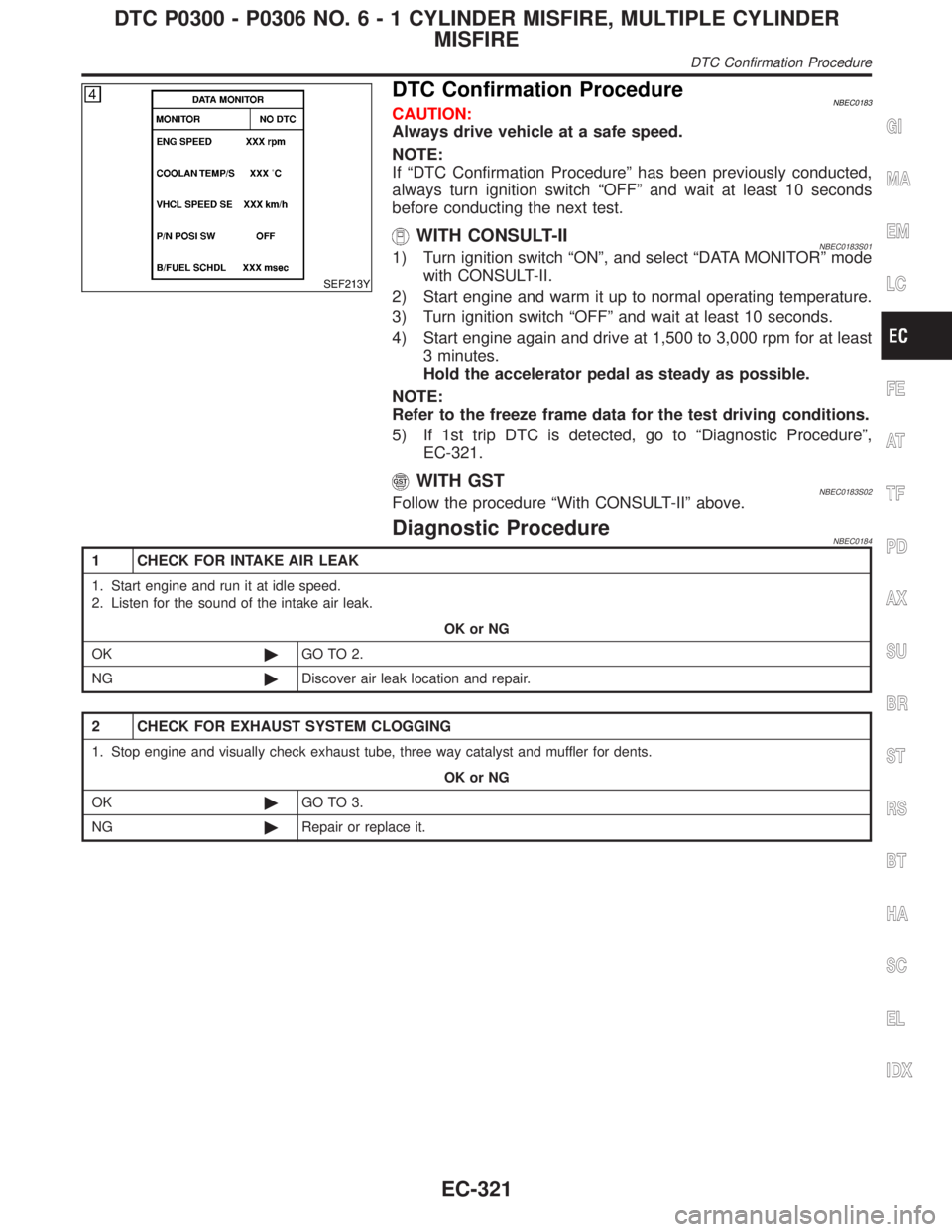
SEF213Y
DTC Confirmation ProcedureNBEC0183CAUTION:
Always drive vehicle at a safe speed.
NOTE:
If ªDTC Confirmation Procedureº has been previously conducted,
always turn ignition switch ªOFFº and wait at least 10 seconds
before conducting the next test.
WITH CONSULT-IINBEC0183S011) Turn ignition switch ªONº, and select ªDATA MONITORº mode
with CONSULT-II.
2) Start engine and warm it up to normal operating temperature.
3) Turn ignition switch ªOFFº and wait at least 10 seconds.
4) Start engine again and drive at 1,500 to 3,000 rpm for at least
3 minutes.
Hold the accelerator pedal as steady as possible.
NOTE:
Refer to the freeze frame data for the test driving conditions.
5) If 1st trip DTC is detected, go to ªDiagnostic Procedureº,
EC-321.
WITH GSTNBEC0183S02Follow the procedure ªWith CONSULT-IIº above.
Diagnostic ProcedureNBEC0184
1 CHECK FOR INTAKE AIR LEAK
1. Start engine and run it at idle speed.
2. Listen for the sound of the intake air leak.
OK or NG
OK©GO TO 2.
NG©Discover air leak location and repair.
2 CHECK FOR EXHAUST SYSTEM CLOGGING
1. Stop engine and visually check exhaust tube, three way catalyst and muffler for dents.
OK or NG
OK©GO TO 3.
NG©Repair or replace it.
GI
MA
EM
LC
FE
AT
TF
PD
AX
SU
BR
ST
RS
BT
HA
SC
EL
IDX
DTC P0300 - P0306 NO.6-1CYLINDER MISFIRE, MULTIPLE CYLINDER
MISFIRE
DTC Confirmation Procedure
EC-321
Page 870 of 2395
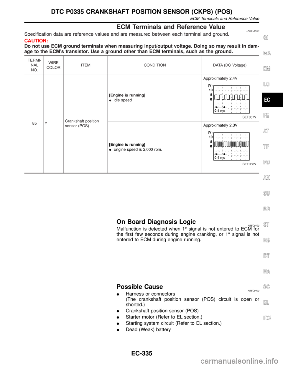
ECM Terminals and Reference Value=NBEC0664Specification data are reference values and are measured between each terminal and ground.
CAUTION:
Do not use ECM ground terminals when measuring input/output voltage. Doing so may result in dam-
age to the ECM's transistor. Use a ground other than ECM terminals, such as the ground.
TERMI-
NAL
NO.WIRE
COLORITEM CONDITION DATA (DC Voltage)
85 YCrankshaft position
sensor (POS)[Engine is running]
IIdle speedApproximately 2.4V
SEF057V
[Engine is running]
IEngine speed is 2,000 rpm.Approximately 2.3V
SEF058V
On Board Diagnosis LogicNBEC0193Malfunction is detected when 1É signal is not entered to ECM for
the first few seconds during engine cranking, or 1É signal is not
entered to ECM during engine running.
Possible CauseNBEC0493IHarness or connectors
(The crankshaft position sensor (POS) circuit is open or
shorted.)
ICrankshaft position sensor (POS)
IStarter motor (Refer to EL section.)
IStarting system circuit (Refer to EL section.)
IDead (Weak) battery
GI
MA
EM
LC
FE
AT
TF
PD
AX
SU
BR
ST
RS
BT
HA
SC
EL
IDX
DTC P0335 CRANKSHAFT POSITION SENSOR (CKPS) (POS)
ECM Terminals and Reference Value
EC-335