Engine control INFINITI QX4 2001 Factory User Guide
[x] Cancel search | Manufacturer: INFINITI, Model Year: 2001, Model line: QX4, Model: INFINITI QX4 2001Pages: 2395, PDF Size: 43.2 MB
Page 33 of 2395
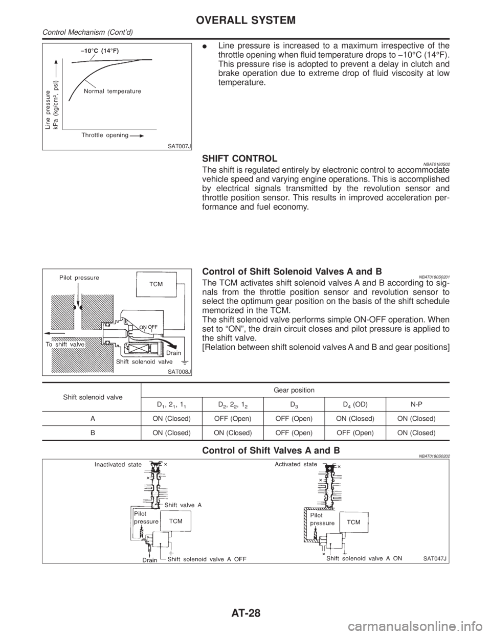
SAT007J
ILine pressure is increased to a maximum irrespective of the
throttle opening when fluid temperature drops to þ10ÉC (14ÉF).
This pressure rise is adopted to prevent a delay in clutch and
brake operation due to extreme drop of fluid viscosity at low
temperature.
SHIFT CONTROLNBAT0180S02The shift is regulated entirely by electronic control to accommodate
vehicle speed and varying engine operations. This is accomplished
by electrical signals transmitted by the revolution sensor and
throttle position sensor. This results in improved acceleration per-
formance and fuel economy.
SAT008J
Control of Shift Solenoid Valves A and BNBAT0180S0201The TCM activates shift solenoid valves A and B according to sig-
nals from the throttle position sensor and revolution sensor to
select the optimum gear position on the basis of the shift schedule
memorized in the TCM.
The shift solenoid valve performs simple ON-OFF operation. When
set to ªONº, the drain circuit closes and pilot pressure is applied to
the shift valve.
[Relation between shift solenoid valves A and B and gear positions]
Shift solenoid valveGear position
D
1,21,11D2,22,12D3D4(OD) N-P
A ON (Closed) OFF (Open) OFF (Open) ON (Closed) ON (Closed)
B ON (Closed) ON (Closed) OFF (Open) OFF (Open) ON (Closed)
Control of Shift Valves A and BNBAT0180S0202
SAT047J
OVERALL SYSTEM
Control Mechanism (Cont'd)
AT-28
Page 35 of 2395
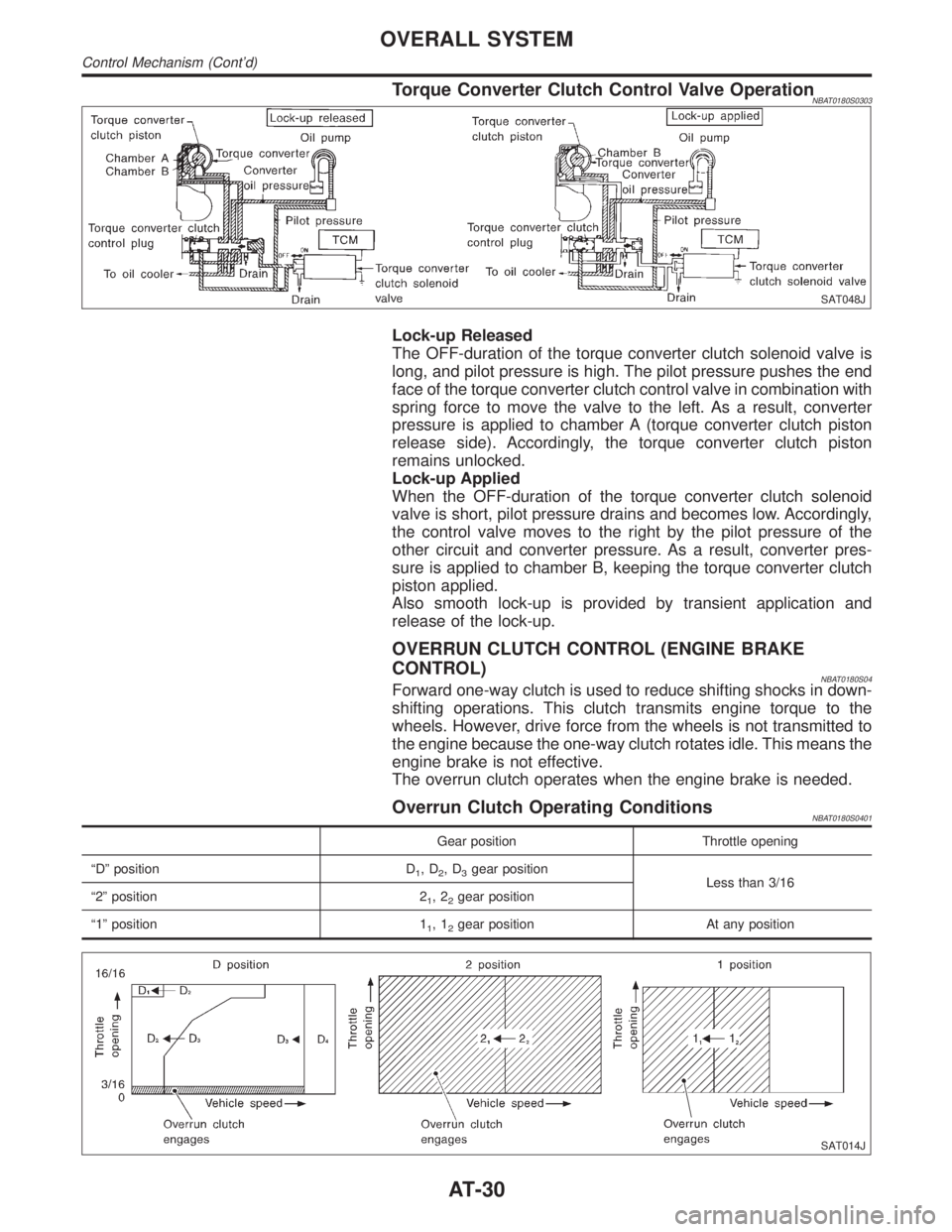
Torque Converter Clutch Control Valve OperationNBAT0180S0303
SAT048J
Lock-up Released
The OFF-duration of the torque converter clutch solenoid valve is
long, and pilot pressure is high. The pilot pressure pushes the end
face of the torque converter clutch control valve in combination with
spring force to move the valve to the left. As a result, converter
pressure is applied to chamber A (torque converter clutch piston
release side). Accordingly, the torque converter clutch piston
remains unlocked.
Lock-up Applied
When the OFF-duration of the torque converter clutch solenoid
valve is short, pilot pressure drains and becomes low. Accordingly,
the control valve moves to the right by the pilot pressure of the
other circuit and converter pressure. As a result, converter pres-
sure is applied to chamber B, keeping the torque converter clutch
piston applied.
Also smooth lock-up is provided by transient application and
release of the lock-up.
OVERRUN CLUTCH CONTROL (ENGINE BRAKE
CONTROL)
NBAT0180S04Forward one-way clutch is used to reduce shifting shocks in down-
shifting operations. This clutch transmits engine torque to the
wheels. However, drive force from the wheels is not transmitted to
the engine because the one-way clutch rotates idle. This means the
engine brake is not effective.
The overrun clutch operates when the engine brake is needed.
Overrun Clutch Operating ConditionsNBAT0180S0401
Gear position Throttle opening
ªDº position D
1,D2,D3gear position
Less than 3/16
ª2º position 2
1,22gear position
ª1º position 1
1,12gear position At any position
SAT014J
OVERALL SYSTEM
Control Mechanism (Cont'd)
AT-30
Page 36 of 2395
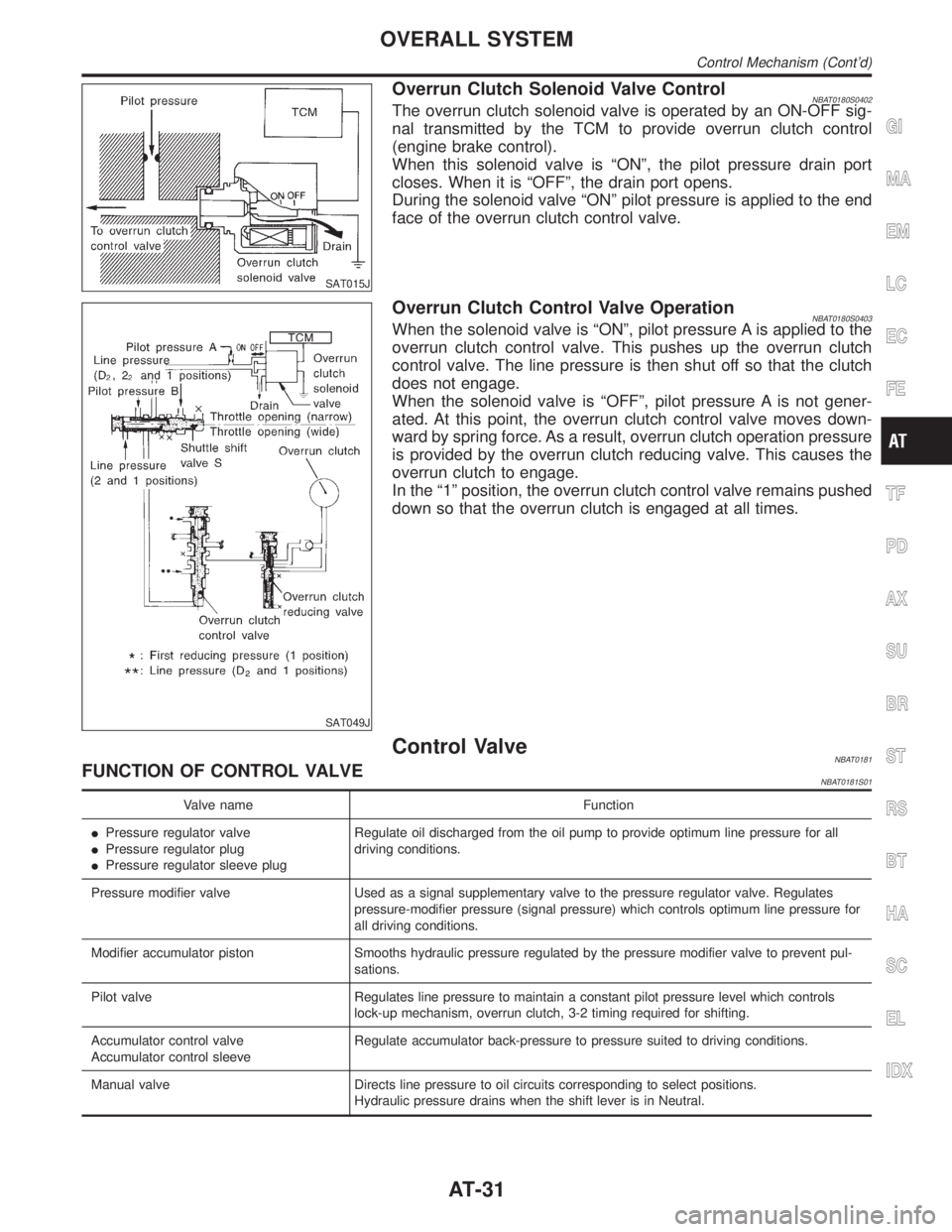
SAT015J
Overrun Clutch Solenoid Valve ControlNBAT0180S0402The overrun clutch solenoid valve is operated by an ON-OFF sig-
nal transmitted by the TCM to provide overrun clutch control
(engine brake control).
When this solenoid valve is ªONº, the pilot pressure drain port
closes. When it is ªOFFº, the drain port opens.
During the solenoid valve ªONº pilot pressure is applied to the end
face of the overrun clutch control valve.
SAT049J
Overrun Clutch Control Valve OperationNBAT0180S0403When the solenoid valve is ªONº, pilot pressure A is applied to the
overrun clutch control valve. This pushes up the overrun clutch
control valve. The line pressure is then shut off so that the clutch
does not engage.
When the solenoid valve is ªOFFº, pilot pressure A is not gener-
ated. At this point, the overrun clutch control valve moves down-
ward by spring force. As a result, overrun clutch operation pressure
is provided by the overrun clutch reducing valve. This causes the
overrun clutch to engage.
In the ª1º position, the overrun clutch control valve remains pushed
down so that the overrun clutch is engaged at all times.
Control ValveNBAT0181FUNCTION OF CONTROL VALVENBAT0181S01
Valve name Function
IPressure regulator valve
IPressure regulator plug
IPressure regulator sleeve plugRegulate oil discharged from the oil pump to provide optimum line pressure for all
driving conditions.
Pressure modifier valve Used as a signal supplementary valve to the pressure regulator valve. Regulates
pressure-modifier pressure (signal pressure) which controls optimum line pressure for
all driving conditions.
Modifier accumulator piston Smooths hydraulic pressure regulated by the pressure modifier valve to prevent pul-
sations.
Pilot valve Regulates line pressure to maintain a constant pilot pressure level which controls
lock-up mechanism, overrun clutch, 3-2 timing required for shifting.
Accumulator control valve
Accumulator control sleeveRegulate accumulator back-pressure to pressure suited to driving conditions.
Manual valve Directs line pressure to oil circuits corresponding to select positions.
Hydraulic pressure drains when the shift lever is in Neutral.
GI
MA
EM
LC
EC
FE
TF
PD
AX
SU
BR
ST
RS
BT
HA
SC
EL
IDX
OVERALL SYSTEM
Control Mechanism (Cont'd)
AT-31
Page 37 of 2395
Valve name Function
Shift valve A Simultaneously switches three oil circuits using output pressure of shift solenoid valve
A to meet driving conditions (vehicle speed, throttle opening, etc.).
Provides automatic downshifting and up-shifting (1st,2nd,3rd,4th gears/4th
,3rd,2nd,1st gears) in combination with shift valve B.
Shift valve B Simultaneously switches three oil circuits using output pressure of shift solenoid valve
B in relation to driving conditions (vehicle speed, throttle opening, etc.).
Provides automatic downshifting and up-shifting (1st,2nd,3rd,4th gears/4th
,3rd,2nd,1st gears) in combination with shift valve A.
Shuttle shift valve S Switches hydraulic circuits to provide 3-2 timing control and overrun clutch control in
relation to the throttle opening.
Inactivates the overrun clutch to prevent interlocking in 4th gear when the throttle is
wide open.
Overrun clutch control valve Switches hydraulic circuits to prevent engagement of the overrun clutch simulta-
neously with application of the brake band in 4th gear. (Interlocking occurs if the
overrun clutch engages during D
4gear operation.)
4-2 relay valve Memorizes that the transmission is in 4th gear. Prevents the transmission from down-
shifting from 4th gear to 3rd and then to 2nd in combination with 4-2 sequence valve
and shift valves A and B when downshifting from 4th to 2nd gear.
4-2 sequence valve Prevents band servo pressure from draining before high clutch operating pressure
and band servo releasing pressure drain (from the same circuit) during downshifting
from 4th to 2nd gear.
Servo charger valve An accumulator and a one-way orifice are used in the 2nd gear band servo oil circuit
to dampen shifting shock when shifting from 1st to 2nd gear.
To maintain adequate flow rate when downshifting from 4th or 3rd gear to 2nd gear,
the servo charger valve directs 2nd gear band servo hydraulic pressure to the circuit
without going through the one-way orifice when downshifting from 3rd or a higher
gear.
3-2 timing valve Prevents a late operation of the brake band when shifting selector lever from ªDº to
ª1º or ª2º position while driving in D
3.
ª1º reducing valve Reduces low & reverse brake pressure to dampen engine-brake shock when down-
shifting from the ª1º position 2nd gear to 1st gear.
Overrun clutch reducing valve Reduces oil pressure directed to the overrun clutch and prevents engine-brake shock.
In ª1º and ª2º positions, line pressure acts on the overrun clutch reducing valve to
increase the pressure-regulating point, with resultant engine brake capability.
Torque converter relief valve Prevents an excessive rise in torque converter pressure.
Torque converter clutch control valve,
torque converter clutch control plug and
torque converter clutch control sleeveActivate or inactivate the lock-up function.
Also provide smooth lock-up through transient application and release of the lock-up
system.
Shuttle shift valve D Switches hydraulic circuits so that output pressure of the torque converter clutch sole-
noid valve acts on the lock-up valve in the ªDº position of 2nd, 3rd and 4th gears. (In
the ªDº position 1st gear, lock-up is inhibited.)
ILock-up control is not affected in ªDº position 2nd, 3rd or 4th gears, unless output
pressure of the torque converter clutch solenoid valve is generated by a signal
from the control unit.
OVERALL SYSTEM
Control Valve (Cont'd)
AT-32
Page 44 of 2395
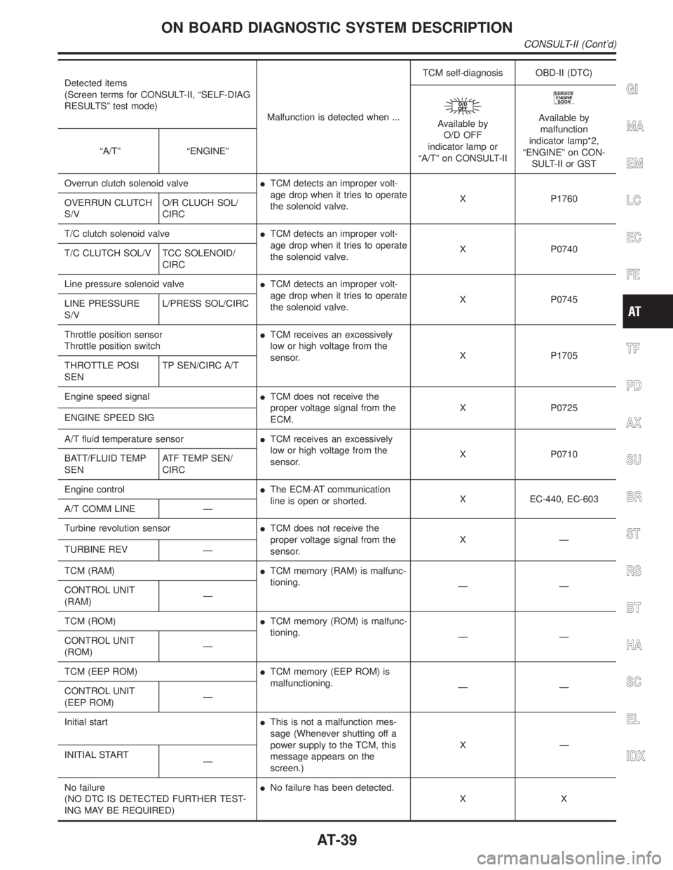
Detected items
(Screen terms for CONSULT-II, ªSELF-DIAG
RESULTSº test mode)
Malfunction is detected when ...TCM self-diagnosis OBD-II (DTC)
Available by
O/D OFF
indicator lamp or
ªA/Tº on CONSULT-IIAvailable by
malfunction
indicator lamp*2,
ªENGINEº on CON-
SULT-II or GST ªA/Tº ªENGINEº
Overrun clutch solenoid valveITCM detects an improper volt-
age drop when it tries to operate
the solenoid valve.X P1760
OVERRUN CLUTCH
S/VO/R CLUCH SOL/
CIRC
T/C clutch solenoid valveITCM detects an improper volt-
age drop when it tries to operate
the solenoid valve.X P0740
T/C CLUTCH SOL/V TCC SOLENOID/
CIRC
Line pressure solenoid valveITCM detects an improper volt-
age drop when it tries to operate
the solenoid valve.X P0745
LINE PRESSURE
S/VL/PRESS SOL/CIRC
Throttle position sensor
Throttle position switchITCM receives an excessively
low or high voltage from the
sensor.X P1705
THROTTLE POSI
SENTP SEN/CIRC A/T
Engine speed signalITCM does not receive the
proper voltage signal from the
ECM.X P0725
ENGINE SPEED SIG
A/T fluid temperature sensorITCM receives an excessively
low or high voltage from the
sensor.X P0710
BATT/FLUID TEMP
SENATF TEMP SEN/
CIRC
Engine controlIThe ECM-AT communication
line is open or shorted.X EC-440, EC-603
A/T COMM LINE Ð
Turbine revolution sensorITCM does not receive the
proper voltage signal from the
sensor.XÐ
TURBINE REV
Ð
TCM (RAM)ITCM memory (RAM) is malfunc-
tioning.
ÐÐ
CONTROL UNIT
(RAM)Ð
TCM (ROM)ITCM memory (ROM) is malfunc-
tioning.
ÐÐ
CONTROL UNIT
(ROM)Ð
TCM (EEP ROM)ITCM memory (EEP ROM) is
malfunctioning.
ÐÐ
CONTROL UNIT
(EEP ROM)Ð
Initial startIThis is not a malfunction mes-
sage (Whenever shutting off a
power supply to the TCM, this
message appears on the
screen.)XÐ
INITIAL START
Ð
No failure
(NO DTC IS DETECTED FURTHER TEST-
ING MAY BE REQUIRED)INo failure has been detected.
XX
GI
MA
EM
LC
EC
FE
TF
PD
AX
SU
BR
ST
RS
BT
HA
SC
EL
IDX
ON BOARD DIAGNOSTIC SYSTEM DESCRIPTION
CONSULT-II (Cont'd)
AT-39
Page 45 of 2395

X: Applicable
Ð: Not applicable
*1: These malfunctions cannot be displayed by MIL
if another malfunction is assigned to MIL.
*2: Refer to EC-74, ªDESCRIPTIONº.
DATA MONITOR MODE (A/T)NBAT0184S03
Item DisplayMonitor item
Description Remarks
TCM input
signalsMain sig-
nals
Vehicle speed sensor 1
(A/T)
(Revolution sensor)VHCL/S SE´A/T
[km/h] or [mph]
XÐIVehicle speed computed
from signal of revolution
sensor is displayed.When racing engine in ªNº
or ªPº position with vehicle
stationary, CONSULT-II
data may not indicate 0
km/h (0 mph).
Vehicle speed sensor 2
(Meter)VHCL/S SE´MTR
[km/h] or [mph]
XÐIVehicle speed computed
from signal of vehicle
speed sensor is dis-
played.Vehicle speed display may
not be accurate under
approx. 10 km/h (6 mph). It
may not indicate 0 km/h (0
mph) when vehicle is sta-
tionary.
Throttle position sensor THRTL POS
SEN
[V]XÐIThrottle position sensor
signal voltage is dis-
played.
A/T fluid temperature sen-
sorFLUID TEMP SE
[V]
XÐIA/T fluid temperature
sensor signal voltage is
displayed.
ISignal voltage lowers as
fluid temperature rises.
Battery voltage BATTERY VOLT
[V]XÐISource voltage of TCM
is displayed.
Engine speed ENGINE SPEED
[rpm]
XXIEngine speed, computed
from engine speed
signal, is displayed.Engine speed display may
not be accurate under
approx. 800 rpm. It may
not indicate 0 rpm even
when engine is not run-
ning.
Turbine revolution sensor TURBINE REV
[rpm]
XÐITurbine revolution com-
puted from signal of tur-
bine revolution sensor is
displayed.Error may occur under
approx. 800 rpm and will
not indicate 0 rpm even if
engine is not running.
Overdrive control switch OVERDRIVE SW
[ON/OFF] X ÐION/OFF state computed
from signal of overdrive
control SW is displayed.
PN position switch PN POSI SW
[ON/OFF] X ÐION/OFF state computed
from signal of PN posi-
tion SW is displayed.
R position switch R POSITION SW
[ON/OFF] X ÐION/OFF state computed
from signal of R position
SW is displayed.
D position switch D POSITION SW
[ON/OFF] X ÐION/OFF state computed
from signal of D position
SW is displayed.
2 position switch 2 POSITION SW
[ON/OFF]
XÐION/OFF status, com-
puted from signal of 2
position SW, is dis-
played.
ON BOARD DIAGNOSTIC SYSTEM DESCRIPTION
CONSULT-II (Cont'd)
AT-40
Page 53 of 2395
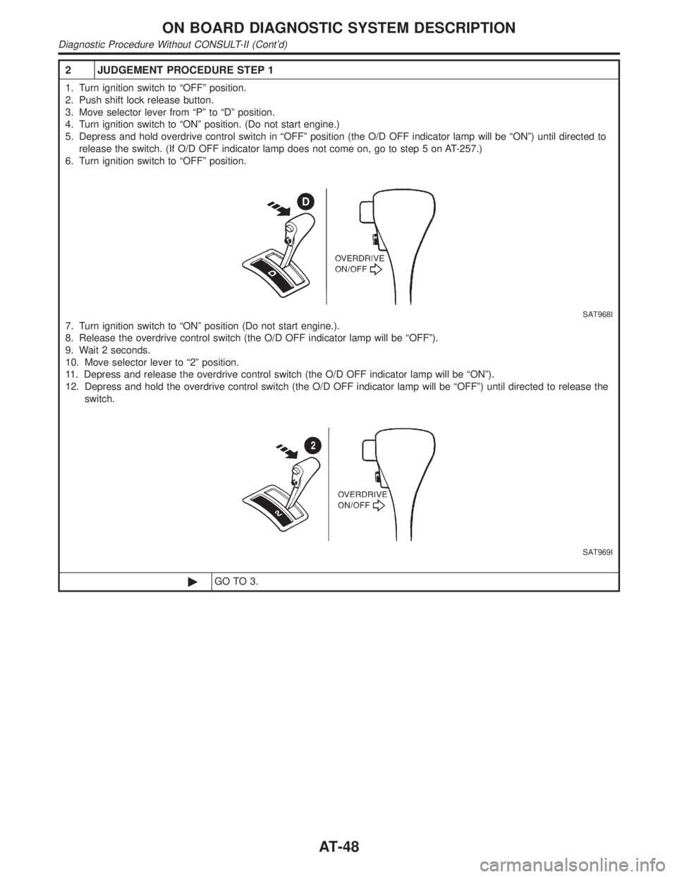
2 JUDGEMENT PROCEDURE STEP 1
1. Turn ignition switch to ªOFFº position.
2. Push shift lock release button.
3. Move selector lever from ªPº to ªDº position.
4. Turn ignition switch to ªONº position. (Do not start engine.)
5. Depress and hold overdrive control switch in ªOFFº position (the O/D OFF indicator lamp will be ªONº) until directed to
release the switch. (If O/D OFF indicator lamp does not come on, go to step 5 on AT-257.)
6. Turn ignition switch to ªOFFº position.
SAT968I
7. Turn ignition switch to ªONº position (Do not start engine.).
8. Release the overdrive control switch (the O/D OFF indicator lamp will be ªOFFº).
9. Wait 2 seconds.
10. Move selector lever to ª2º position.
11. Depress and release the overdrive control switch (the O/D OFF indicator lamp will be ªONº).
12. Depress and hold the overdrive control switch (the O/D OFF indicator lamp will be ªOFFº) until directed to release the
switch.
SAT969I
©GO TO 3.
ON BOARD DIAGNOSTIC SYSTEM DESCRIPTION
Diagnostic Procedure Without CONSULT-II (Cont'd)
AT-48
Page 58 of 2395

SAT631IB
IntroductionNBAT0019
SAT632I
SEF234G
The TCM receives a signal from the vehicle speed sensor, throttle
position sensor or PNP switch and provides shift control or lock-up
control via A/T solenoid valves.
The TCM also communicates with the ECM by means of a signal
sent from sensing elements used with the OBD-related parts of the
A/T system for malfunction-diagnostic purposes. The TCM is
capable of diagnosing malfunctioning parts while the ECM can
store malfunctions in its memory.
Input and output signals must always be correct and stable in the
operation of the A/T system. The A/T system must be in good
operating condition and be free of valve seizure, solenoid valve
malfunction, etc.
It is much more difficult to diagnose a problem that occurs intermit-
tently rather than continuously. Most intermittent problems are
caused by poor electric connections or improper wiring. In this
case, careful checking of suspected circuits may help prevent the
replacement of good parts.
A visual check only may not find the cause of the problems. A road
test with CONSULT-II (or GST) or a circuit tester connected should
be performed. Follow the ªWork Flowº. Refer to AT-57.
Before undertaking actual checks, take a few minutes to talk with
a customer who approaches with a driveability complaint. The cus-
tomer can supply good information about such problems, espe-
cially intermittent ones. Find out what symptoms are present and
under what conditions they occur. A ªDiagnostic Worksheetº like the
example (AT-55) should be used.
Start your diagnosis by looking for ªconventionalº problems first.
This will help troubleshoot driveability problems on an electronically
controlled engine vehicle.
Also check related Service bulletins.GI
MA
EM
LC
EC
FE
TF
PD
AX
SU
BR
ST
RS
BT
HA
SC
EL
IDX
TROUBLE DIAGNOSIS Ð INTRODUCTION
Introduction
AT-53
Page 60 of 2395

Diagnostic Worksheet=NBAT0019S0102
1.lRead the Fail-safe Remarks and listen to customer complaints. AT-8
2.lCHECK A/T FLUIDAT-59
lLeakage (Follow specified procedure)
lFluid condition
lFluid level
3. Perform STALL TEST and LINE PRESSURE TEST. AT-59, AT-62
lStall test Ð Mark possible damaged components/others.
lTorque converter one-way clutch
lReverse clutch
lForward clutch
lOverrun clutch
lForward one-way clutchlLow & reverse brake
lLow one-way clutch
lEngine
lLine pressure is low
lClutches and brakes except high clutch and
brake band are OK
lPressure test Ð Suspected parts:
4.lPerform all ROAD TEST and mark required procedures. AT-63
4-1. Check before engine is started.AT-64
lSELF-DIAGNOSTIC PROCEDURE - Mark detected items.
lDTC P0705 PNP switch, AT-99.
lDTC P0710 A/T fluid temperature sensor, AT-105.
lDTC P0720 Vehicle speed sensor´A/T (Revolution sensor), AT-111.
lDTC P0725 Engine speed signal, AT-116.
lDTC P0740 Torque converter clutch solenoid valve, AT-148.
lDTC P0745 Line pressure solenoid valve, AT-162.
lDTC P0750 Shift solenoid valve A, AT-168.
lDTC P0755 Shift solenoid valve B, AT-172.
lDTC P1705 Throttle position sensor, AT-176.
lDTC P1760 Overrun clutch solenoid valve, AT-185.
lDTC BATT/FLUID TEMP SEN (A/T fluid temperature sensor and TCM power source), AT-190.
lDTC Vehicle speed sensor´MTR, AT-197.
lDTC Turbine revolution sensor, AT-202.
lDTC A/T communication line, AT-207.
lDTC Control unit (RAM), control unit (ROM), AT-211.
lDTC Control unit (EEP ROM), AT-213.
lPNP, overdrive control and throttle position switches, AT-257.
lBattery
lOthers
4-2. Check at idleAT-66
l1. O/D OFF Indicator Lamp Does Not Come On, AT-218.
l2. Engine Cannot Be Started In ªPº And ªNº Position, AT-221.
l3. In ªPº Position, Vehicle Moves Forward Or Backward When Pushed, AT-222.
l4. In ªNº Position, Vehicle Moves, AT-223.
l5. Large Shock. ªNº,ªRº Position, AT-225.
l6. Vehicle Does Not Creep Backward In ªRº Position, AT-227.
l7. Vehicle Does Not Creep Forward In ªDº, ª2º Or ª1º Position, AT-230.GI
MA
EM
LC
EC
FE
TF
PD
AX
SU
BR
ST
RS
BT
HA
SC
EL
IDX
TROUBLE DIAGNOSIS Ð INTRODUCTION
Introduction (Cont'd)
AT-55
Page 61 of 2395

4. 4-3. Cruise testAT-67
AT-71
Part-1
l8. Vehicle Cannot Be Started From D
1, AT-233.
l9. A/T Does Not Shift: D
1,D2Or Does Not Kickdown: D4,D2, AT-236.
l10. A/T Does Not Shift: D
2,D3, AT-239.
l11. A/T Does Not Shift: D
3,D4, AT-242.
l12. A/T Does Not Perform Lock-up, AT-245.
l13. A/T Does Not Hold Lock-up Condition, AT-247.
l14. Lock-up Is Not Released, AT-249.
l15. Engine Speed Does Not Return To Idle (Light Braking D
4,D3), AT-250.
Part-2AT-75
l16. Vehicle Does Not Start From D
1, AT-252.
l9. A/T Does Not Shift: D
1,D2Or Does Not Kickdown: D4,D2, AT-236.
l10. A/T Does Not Shift: D
2,D3, AT-239.
l11. A/T Does Not Shift: D
3,D4, AT-242.
Part-3AT-77
l17. A/T Does Not Shift: D
4,D3When Overdrive Control Switch ªONº,ªOFFº, AT-253
l15. Engine Speed Does Not Return To Idle (Engine Brake In D
3), AT-250.
l18. A/T Does Not Shift: D
3,22, When Selector Lever ªDº,ª2º Position, AT-254.
l15. Engine Speed Does Not Return To Idle (Engine Brake In 2
2), AT-250.
l19. A/T Does Not Shift: 2
2,11, When Selector Lever ª2º,ª1º Position, AT-255.
l20. Vehicle Does Not Decelerate By Engine Brake, AT-256.
lSELF-DIAGNOSTIC PROCEDURE Ð Mark detected items.
lDTC P0705 PNP switch, AT-99.
lDTC P0710 A/T fluid temperature sensor, AT-105.
lDTC P0720 Vehicle speed sensor´A/T (Revolution sensor), AT-111.
lDTC P0725 Engine speed signal, AT-116.
lDTC P0740 Torque converter clutch solenoid valve, AT-148.
lDTC P0745 Line pressure solenoid valve, AT-162.
lDTC P0750 Shift solenoid valve A, AT-168.
lDTC P0755 Shift solenoid valve B, AT-172.
lDTC P1705 Throttle position sensor, AT-176.
lDTC P1760 Overrun clutch solenoid valve, AT-185.
lDTC BATT/FLUID TEMP SEN (A/T fluid temperature sensor and TCM power source), AT-190.
lDTC Vehicle speed sensor´MTR, AT-197.
lDTC Turbine revolution sensor, AT-202.
lDTC A/T communication line, AT-207.
lDTC Control unit (RAM), control unit (ROM), AT-211.
lDTC Control unit (EEP ROM), AT-213.
lPNP, overdrive control and throttle position switches, AT-257.
lBattery
lOthers
5.lFor self-diagnosis NG items, inspect each component. Repair or replace the damaged parts. AT-38
6.lPerform all ROAD TEST and re-mark required procedures. AT-63
7.lPerform DTC CONFIRMATION PROCEDURE for following MIL indicating items and check out NG items.
Refer to EC-60, ªEmission-related Diagnostic Informationº.EC-60
lDTC (P0731, 1103) A/T 1st gear function, AT-120.
lDTC (P0732, 1104) A/T 2nd gear function, AT-126.
lDTC (P0733, 1105) A/T 3rd gear function, AT-132.
lDTC (P0734, 1106) A/T 4th gear function, AT-138.
lDTC (P0744, 1107) A/T TCC S/V function (lock-up), AT-153.
8.lPerform the Diagnostic Procedures for all remaining items marked NG. Repair or replace the damaged
parts.
Refer to the Symptom Chart when you perform the procedures. (The chart also shows some other possible
symptoms and the component inspection orders.)AT-92
AT-97
9.lErase DTC from TCM and ECM memories. AT-35
TROUBLE DIAGNOSIS Ð INTRODUCTION
Introduction (Cont'd)
AT-56