fuse diagram INFINITI QX4 2001 Factory User Guide
[x] Cancel search | Manufacturer: INFINITI, Model Year: 2001, Model line: QX4, Model: INFINITI QX4 2001Pages: 2395, PDF Size: 43.2 MB
Page 1080 of 2395

Diagnostic ProcedureNBEC0325
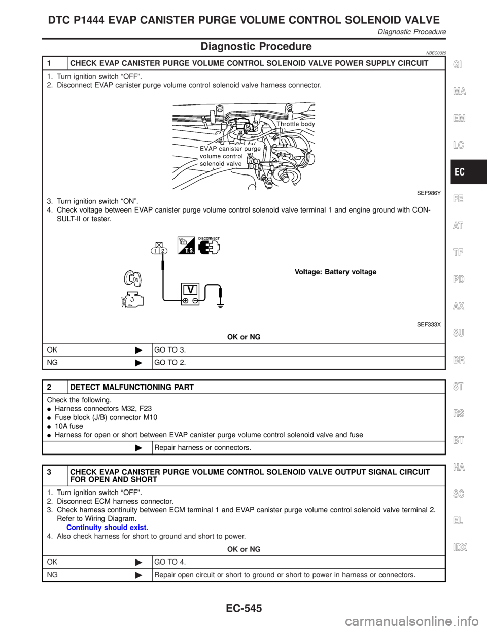
1 CHECK EVAP CANISTER PURGE VOLUME CONTROL SOLENOID VALVE POWER SUPPLY CIRCUIT
1. Turn ignition switch ÂȘOFFÂș.
2. Disconnect EVAP canister purge volume control solenoid valve harness connector.
SEF986Y
3. Turn ignition switch ÂȘONÂș.
4. Check voltage between EVAP canister purge volume control solenoid valve terminal 1 and engine ground with CON-
SULT-II or tester.
SEF333X
OK or NG
OK©GO TO 3.
NG©GO TO 2.
2 DETECT MALFUNCTIONING PART
Check the following.
IHarness connectors M32, F23
IFuse block (J/B) connector M10
I10A fuse
IHarness for open or short between EVAP canister purge volume control solenoid valve and fuse
©Repair harness or connectors.
3 CHECK EVAP CANISTER PURGE VOLUME CONTROL SOLENOID VALVE OUTPUT SIGNAL CIRCUIT
FOR OPEN AND SHORT
1. Turn ignition switch ÂȘOFFÂș.
2. Disconnect ECM harness connector.
3. Check harness continuity between ECM terminal 1 and EVAP canister purge volume control solenoid valve terminal 2.
Refer to Wiring Diagram.
Continuity should exist.
4. Also check harness for short to ground and short to power.
OK or NG
OK©GO TO 4.
NG©Repair open circuit or short to ground or short to power in harness or connectors.
GI
MA
EM
LC
FE
AT
TF
PD
AX
SU
BR
ST
RS
BT
HA
SC
EL
IDX
DTC P1444 EVAP CANISTER PURGE VOLUME CONTROL SOLENOID VALVE
Diagnostic Procedure
EC-545
Page 1124 of 2395

3 CHECK VACUUM CUT VALVE BYPASS VALUE POWER SUPPLY CIRCUIT
1. Turn ignition switch ÂȘOFFÂș.
2. Disconnect vacuum cut valve bypass valve harness connector.
SEF485T
3. Turn ignition switch ÂȘONÂș.
4. Check voltage between vacuum cut valve bypass valve terminal 2 and ground with CONSULT-II or tester.
SEF015Z
OK or NG
OK©GO TO 5.
NG©GO TO 4.
4 DETECT MALFUNCTIONING PART
Check the following.
IHarness connectors M2, B1
IFuse block (J/B) connector M10
IHarness connectors B43, B101 and B151, B152
I10A fuse
IHarness for open or short between vacuum cut valve bypass valve and fuse
©Repair harness or connectors.
5 CHECK VACUUM CUT VALVE BYPASS VALVE OUTPUT SIGNAL CIRCUIT FOR OPEN AND SHORT
1. Turn ignition switch ÂȘOFFÂș.
2. Disconnect ECM harness connector.
3. Check harness continuity between ECM terminal 39 and vacuum cut valve bypass valve terminal 1. Refer to Wiring
Diagram.
Continuity should exist.
4. Also check harness for short to ground and short to power.
OK or NG
OK©GO TO 7.
NG©GO TO 6.
GI
MA
EM
LC
FE
AT
TF
PD
AX
SU
BR
ST
RS
BT
HA
SC
EL
IDX
DTC P1490 VACUUM CUT VALVE BYPASS VALVE (CIRCUIT)
Diagnostic Procedure (Cont'd)
EC-589
Page 1149 of 2395

2 CHECK VIAS CONTROL SOLENOID VALVE POWER SUPPLY CIRCUIT
1. Stop engine.
2. Disconnect VIAS control solenoid valve harness connector.
SEF019Z
3. Turn ignition switch ÂȘONÂș.
4. Check voltage between terminal 1 and ground with CONSULT-II or tester.
SEF603X
OK or NG
OK©GO TO 4.
NG©GO TO 3.
3 DETECT MALFUNCTIONING PART
Check the following.
IHarness connectors M32, F23
I10A fuse
IHarness continuity between fuse and VIAS control solenoid valve
©Repair harness or connectors.
4 CHECK VIAS CONTROL SOLENOID VALVE OUTPUT SIGNAL CIRCUIT FOR OPEN AND SHORT
1. Turn ignition switch ÂȘOFFÂș.
2. Disconnect ECM harness connector.
3. Check harness continuity between ECM terminal 16 and terminal 2. Refer to Wiring Diagram.
Continuity should exist.
4. Also check harness for short to ground and short to power.
OK or NG
OK©GO TO 5.
NG©Repair open circuit or short to ground or short to power in harness or connectors.
VARIABLE INDUCTION AIR CONTROL SYSTEM (VIAS)
Diagnostic Procedure (Cont'd)
EC-614
Page 1154 of 2395

3 CHECK INJECTOR POWER SUPPLY CIRCUIT
1. Turn ignition switch ÂȘOFFÂș.
SEF023Z
2. Turn ignition switch ÂȘONÂș.
3. Check voltage between injector terminal 1 and ground with CONSULT-II or tester.
SEF364Z
OK or NG
OK©GO TO 5.
NG©GO TO 4.
4 DETECT MALFUNCTIONING PART
Check the following.
IHarness connectors M33, F22
IHarness connectors F5, F100
IFuse block (J/B) connector M10
I10A fuse
IHarness for open or short between injector and fuse
©Repair harness or connectors.
5 CHECK INJECTOR OUTPUT SIGNAL CIRCUIT FOR OPEN AND SHORT
1. Turn ignition switch ÂȘOFFÂș.
2. Disconnect ECM harness connector.
3. Check harness continuity between injector terminal 2 and ECM terminals 103, 104, 107, 101, 105, 102. Refer to Wiring
Diagram.
Continuity should exist.
4. Also check harness for short to ground and short to power.
OK or NG
OK©GO TO 7.
NG©GO TO 6.
GI
MA
EM
LC
FE
AT
TF
PD
AX
SU
BR
ST
RS
BT
HA
SC
EL
IDX
INJECTOR
Diagnostic Procedure (Cont'd)
EC-619
Page 1417 of 2395

POWER SUPPLY AND GROUND CIRCUIT CHECK=NBEL0218S03
1 CHECK POWER SUPPLY CIRCUIT FOR ASCD CONTROL UNIT
1. Disconnect ASCD control unit harness connector.
2. Turn ignition switch ON.
3. Check voltage between ASCD control unit harness connector terminal 5 and ground.
SEL256WB
Refer to wiring diagram in EL-227.
Ye s©GO TO 2.
No©Check the following.
I7.5A fuse (No. 11 located in the fuse block)
IHarness for open or short
2 CHECK GROUND CIRCUIT FOR ASCD CONTROL UNIT
Check continuity between ASCD control unit harness connector terminal 17 and body ground.
SEL257WB
Refer to wiring diagram in EL-227.
Ye s©Power supply and ground circuit is OK.
No©Repair harness.
AUTOMATIC SPEED CONTROL DEVICE (ASCD)
Trouble Diagnoses (Cont'd)
EL-232
Page 1418 of 2395

ASCD BRAKE/STOP LAMP SWITCH CHECK=NBEL0218S04
1 CHECK ASCD BRAKE SWITCH CIRCUIT
1. Disconnect ASCD control unit harness connector.
2. Turn ignition switch ON.
3. Check voltage between ASCD control unit harness connector terminal 8 and ground.
SEL258WD
OK or NG
OK©GO TO 2.
NG©Check the following.
IASCD brake switch
Refer to ÂȘElectrical Component InspectionÂș (EL-239).
IPark/neutral position switch
Refer to ÂȘElectrical Component InspectionÂș (EL-239).
IPark/neutral position relay
IHarness for open or short
2 CHECK STOP LAMP SWITCH CIRCUIT
1. Disconnect ASCD control unit harness connector.
2. Check voltage between ASCD control unit harness connector terminal 23 and ground.
SEL259WB
Refer to wiring diagram in EL-226.
OK or NG
OK©ASCD brake/stop lamp switch is OK.
NG©Check the following.
I10A fuse [No. 14, located in the fuse block (J/B)]
IHarness for open or short between ASCD control unit and stop lamp switch
IHarness for open or short between fuse and stop lamp switch
IStop lamp switch
Refer to ÂȘElectrical Component InspectionÂș (EL-239).
GI
MA
EM
LC
EC
FE
AT
TF
PD
AX
SU
BR
ST
RS
BT
HA
SC
IDX
AUTOMATIC SPEED CONTROL DEVICE (ASCD)
Trouble Diagnoses (Cont'd)
EL-233
Page 1419 of 2395

ASCD STEERING SWITCH CHECK=NBEL0218S05
1 CHECK ASCD STEERING SWITCH CIRCUIT FOR ASCD CONTROL UNIT
Check voltage between ASCD control unit harness connector terminals and ground.
SEL260WC
Refer to wiring diagram in EL-226.
OK or NG
OK©ASCD steering switch is OK.
NG©GO TO 2.
2 CHECK POWER SUPPLY FOR ASCD STEERING SWITCH
Does horn work?
Ye s©GO TO 3.
No©Check the following.
I7.5A fuse (No. 52, located in the relay box)
IHorn relay
IHorn circuit
3 CHECK ASCD STEERING SWITCH
1. Disconnect ASCD steering switch.
2. Check continuity between terminals by pushing each switch.
SEL764WA
OK or NG
OK©Check harness for open or short between ASCD steering switch and ASCD control unit.
NG©Replace ASCD steering switch.
AUTOMATIC SPEED CONTROL DEVICE (ASCD)
Trouble Diagnoses (Cont'd)
EL-234
Page 1449 of 2395

KEY SWITCH (INSERT) CHECK=NBEL0110S06
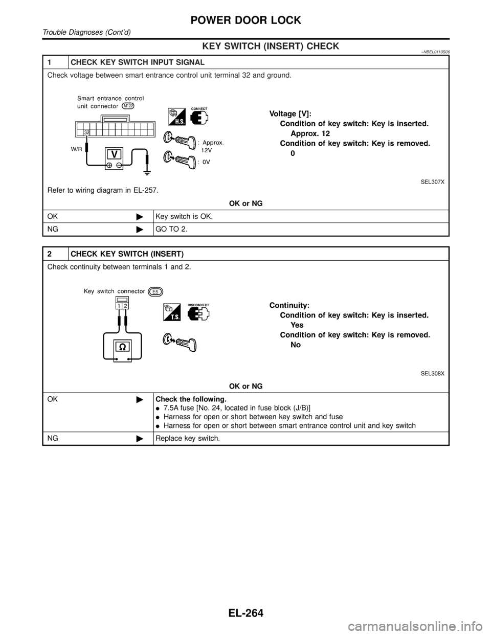
1 CHECK KEY SWITCH INPUT SIGNAL
Check voltage between smart entrance control unit terminal 32 and ground.
SEL307X
Refer to wiring diagram in EL-257.
OK or NG
OK©Key switch is OK.
NG©GO TO 2.
2 CHECK KEY SWITCH (INSERT)
Check continuity between terminals 1 and 2.
SEL308X
OK or NG
OK©Check the following.
I7.5A fuse [No. 24, located in fuse block (J/B)]
IHarness for open or short between key switch and fuse
IHarness for open or short between smart entrance control unit and key switch
NG©Replace key switch.
POWER DOOR LOCK
Trouble Diagnoses (Cont'd)
EL-264
Page 1464 of 2395

POWER SUPPLY AND GROUND CIRCUIT CHECK=NBEL0115S04
1 CHECK MAIN POWER SUPPLY CIRCUIT FOR CONTROL UNIT
1. Disconnect connector from control unit.
2. Check voltage between smart entrance control unit terminal 10 or 11 and ground.
SEL320X
Refer to wiring diagram in EL-274.
OK or NG
OK©GO TO 2.
NG©Check the following.
I40A fusible link (letterf, located in fuse and fusible link box)
I7.5A fuse [No. 24, located in fuse block (J/B)]
IM145 circuit breaker
IHarness for open or short between smart entrance control unit and fuse
2 CHECK IGNITION SWITCH ÂȘACCÂș CIRCUIT
1. Disconnect smart entrance control unit connector.
2. Check voltage between control unit terminal 21 and ground while ignition switch is ÂȘACCÂș.
SEL321X
Refer to wiring diagram in EL-274.
OK or NG
OK©GO TO 3.
NG©Check the following.
I10A fuse [No. 10, located in fuse block (J/B)]
IHarness for open or short between smart entrance control unit and fuse
GI
MA
EM
LC
EC
FE
AT
TF
PD
AX
SU
BR
ST
RS
BT
HA
SC
IDX
MULTI-REMOTE CONTROL SYSTEM
Trouble Diagnoses (Cont'd)
EL-279
Page 1467 of 2395

KEY SWITCH (INSERT) CHECK=NBEL0115S07
1 CHECK KEY SWITCH INPUT SIGNAL
Check voltage between smart entrance control unit terminal 32 and ground.
SEL307X
Refer to wiring diagram in EL-274.
OK or NG
OK©Key switch is OK.
NG©GO TO 2.
2 CHECK KEY SWITCH (INSERT)
Check continuity between terminals 1 and 2.
SEL308X
OK or NG
OK©Check the following.
I7.5A fuse [No. 24, located in fuse block (J/B)]
IHarness for open or short between key switch and fuse
IHarness for open or short between smart entrance control unit and key switch
NG©Replace key switch.
MULTI-REMOTE CONTROL SYSTEM
Trouble Diagnoses (Cont'd)
EL-282