warning light INFINITI QX4 2001 Factory User Guide
[x] Cancel search | Manufacturer: INFINITI, Model Year: 2001, Model line: QX4, Model: INFINITI QX4 2001Pages: 2395, PDF Size: 43.2 MB
Page 1225 of 2395

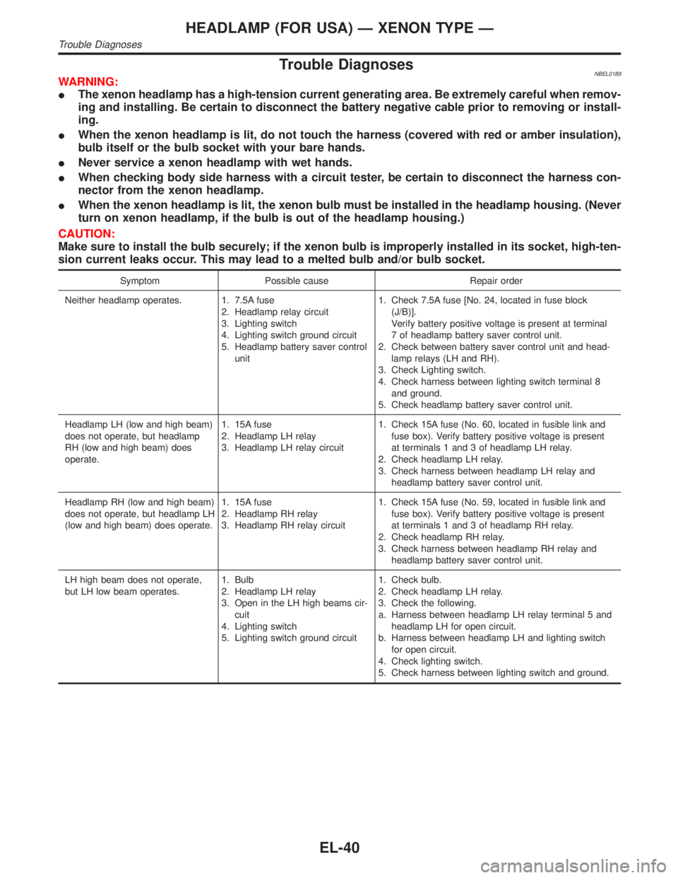
Trouble DiagnosesNBEL0189WARNING:
IThe xenon headlamp has a high-tension current generating area. Be extremely careful when remov-
ing and installing. Be certain to disconnect the battery negative cable prior to removing or install-
ing.
IWhen the xenon headlamp is lit, do not touch the harness (covered with red or amber insulation),
bulb itself or the bulb socket with your bare hands.
INever service a xenon headlamp with wet hands.
IWhen checking body side harness with a circuit tester, be certain to disconnect the harness con-
nector from the xenon headlamp.
IWhen the xenon headlamp is lit, the xenon bulb must be installed in the headlamp housing. (Never
turn on xenon headlamp, if the bulb is out of the headlamp housing.)
CAUTION:
Make sure to install the bulb securely; if the xenon bulb is improperly installed in its socket, high-ten-
sion current leaks occur. This may lead to a melted bulb and/or bulb socket.
Symptom Possible cause Repair order
Neither headlamp operates. 1. 7.5A fuse
2. Headlamp relay circuit
3. Lighting switch
4. Lighting switch ground circuit
5. Headlamp battery saver control
unit1. Check 7.5A fuse [No. 24, located in fuse block
(J/B)].
Verify battery positive voltage is present at terminal
7 of headlamp battery saver control unit.
2. Check between battery saver control unit and head-
lamp relays (LH and RH).
3. Check Lighting switch.
4. Check harness between lighting switch terminal 8
and ground.
5. Check headlamp battery saver control unit.
Headlamp LH (low and high beam)
does not operate, but headlamp
RH (low and high beam) does
operate.1. 15A fuse
2. Headlamp LH relay
3. Headlamp LH relay circuit1. Check 15A fuse (No. 60, located in fusible link and
fuse box). Verify battery positive voltage is present
at terminals 1 and 3 of headlamp LH relay.
2. Check headlamp LH relay.
3. Check harness between headlamp LH relay and
headlamp battery saver control unit.
Headlamp RH (low and high beam)
does not operate, but headlamp LH
(low and high beam) does operate.1. 15A fuse
2. Headlamp RH relay
3. Headlamp RH relay circuit1. Check 15A fuse (No. 59, located in fusible link and
fuse box). Verify battery positive voltage is present
at terminals 1 and 3 of headlamp RH relay.
2. Check headlamp RH relay.
3. Check harness between headlamp RH relay and
headlamp battery saver control unit.
LH high beam does not operate,
but LH low beam operates.1. Bulb
2. Headlamp LH relay
3. Open in the LH high beams cir-
cuit
4. Lighting switch
5. Lighting switch ground circuit1. Check bulb.
2. Check headlamp LH relay.
3. Check the following.
a. Harness between headlamp LH relay terminal 5 and
headlamp LH for open circuit.
b. Harness between headlamp LH and lighting switch
for open circuit.
4. Check lighting switch.
5. Check harness between lighting switch and ground.
HEADLAMP (FOR USA) Ð XENON TYPE Ð
Trouble Diagnoses
EL-40
Page 1228 of 2395

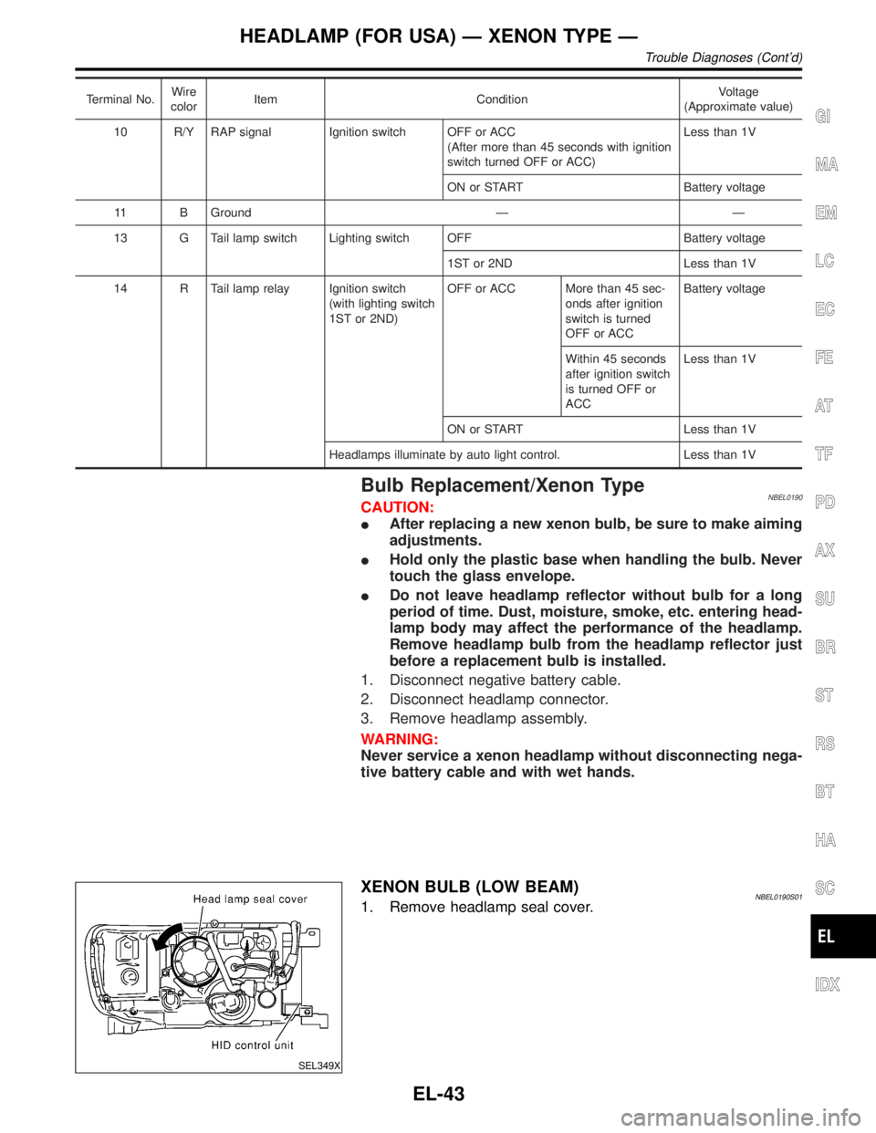
Terminal No.Wire
colorItem ConditionVoltage
(Approximate value)
10 R/Y RAP signal Ignition switch OFF or ACC
(After more than 45 seconds with ignition
switch turned OFF or ACC)Less than 1V
ON or START Battery voltage
11 B Ground Ð Ð
13 G Tail lamp switch Lighting switch OFF Battery voltage
1ST or 2ND Less than 1V
14 R Tail lamp relay Ignition switch
(with lighting switch
1ST or 2ND)OFF or ACC More than 45 sec-
onds after ignition
switch is turned
OFF or ACCBattery voltage
Within 45 seconds
after ignition switch
is turned OFF or
ACCLess than 1V
ON or START Less than 1V
Headlamps illuminate by auto light control. Less than 1V
Bulb Replacement/Xenon TypeNBEL0190CAUTION:
IAfter replacing a new xenon bulb, be sure to make aiming
adjustments.
IHold only the plastic base when handling the bulb. Never
touch the glass envelope.
IDo not leave headlamp reflector without bulb for a long
period of time. Dust, moisture, smoke, etc. entering head-
lamp body may affect the performance of the headlamp.
Remove headlamp bulb from the headlamp reflector just
before a replacement bulb is installed.
1. Disconnect negative battery cable.
2. Disconnect headlamp connector.
3. Remove headlamp assembly.
WARNING:
Never service a xenon headlamp without disconnecting nega-
tive battery cable and with wet hands.
SEL349X
XENON BULB (LOW BEAM)NBEL0190S011. Remove headlamp seal cover.
GI
MA
EM
LC
EC
FE
AT
TF
PD
AX
SU
BR
ST
RS
BT
HA
SC
IDX
HEADLAMP (FOR USA) Ð XENON TYPE Ð
Trouble Diagnoses (Cont'd)
EL-43
Page 1310 of 2395

Component Parts and Harness Connector
Location
NBEL0052
SEL046W
System DescriptionNBEL0053The warning chime is controlled by the smart entrance control unit.
The warning chime is located in the smart entrance control unit.
Power is supplied at all times
Ithrough 7.5A fuse [No. 24, located in the fuse block (J/B)]
Ito smart entrance control unit terminal 10, and
Ito key switch terminal 2, and
Ithrough 10A fuse [No. 61, located in the fuse block (J/B)]
Ito tail lamp relay terminals 2 and 3.
With the ignition switch in the ON or START position, power is supplied
Ithrough 7.5A fuse [No. 11, located in the fuse block (J/B)]
Ito smart entrance control unit terminal 33.
Ground is supplied to smart entrance control unit terminal 16 through body grounds M77 and M111.
IGNITION KEY WARNING CHIMENBEL0053S01With the key in the ignition switch in the OFF or ACC position, and the driver's door open, the warning chime
will sound. Power is supplied
Ifrom key switch terminal 1
Ito smart entrance control unit terminal 32.
Ground is supplied
Ifrom front door switch LH terminal 1
Ito smart entrance control unit terminal 29.
Front door switch LH terminal 2 is grounded through body grounds B11, B22 and D210.
LIGHT WARNING CHIMENBEL0053S02With ignition switch OFF or ACC, driver's door open, warning chime will sound. [Except when headlamp bat-
tery saver control operates (for 45 seconds after ignition switch is turned to OFF or ACC position) and head-
lamps do not illuminate.] Power is supplied.
Ifrom tail lamp relay terminal 5
Ito smart entrance control unit terminal 34.
Ground is supplied
Ifrom front door switch LH terminal 1
GI
MA
EM
LC
EC
FE
AT
TF
PD
AX
SU
BR
ST
RS
BT
HA
SC
IDX
WARNING CHIME
Component Parts and Harness Connector Location
EL-125
Page 1314 of 2395

Trouble DiagnosesNBEL0055SYMPTOM CHARTNBEL0055S01
REFERENCE PAGE (EL- ) 129 131 133 134 135
SYMPTOM
POWER SUPPLY AND GROUND CIRCUIT CHECK
LIGHTING SWITCH INPUT SIGNAL CHECK
KEY SWITCH (INSERT) CHECK
SEAT BELT BUCKLE SWITCH CHECK
DRIVER SIDE DOOR SWITCH CHECK
Light warning chime does not acti-
vate.XX X
Ignition key warning chime does not
activate.XXX
Seat belt warning chime does not
activate.XX
All warning chimes do not activate. X
SEL301X
POWER SUPPLY AND GROUND CIRCUIT CHECKNBEL0055S02Power Supply Circuit CheckNBEL0055S0201
Terminals Ignition switch position
(+) (þ) OFF ACC ON
10 GroundBattery
voltageBattery
voltageBattery
voltage
33 Ground 0V 0VBattery
voltage
GI
MA
EM
LC
EC
FE
AT
TF
PD
AX
SU
BR
ST
RS
BT
HA
SC
IDX
WARNING CHIME
Trouble Diagnoses
EL-129
Page 1316 of 2395

LIGHTING SWITCH INPUT SIGNAL CHECK=NBEL0055S03
1 CHECK LIGHTING SWITCH INPUT SIGNAL
Check voltage between smart entrance control unit terminal 34 and ground.
SEL377X
OK or NG
OK©Lighting switch is OK.
NG©GO TO 2.
2 CHECK FUSE
Is 10A fuse (No. 61, located in the fuse and fusible link box) OK?
OK or NG
OK©GO TO 3.
NG©Replace fuse.
3 CHECK TAIL LAMP RELAY CIRCUIT
Check voltage between headlamp battery saver control unit terminal 6, 14 and ground.
SEL378X
OK or NG
OK©Check the following.
ITail lamp relay
IHarness for open or short between smart entrance control unit and tail lamp relay.
NG©GO TO 4.
GI
MA
EM
LC
EC
FE
AT
TF
PD
AX
SU
BR
ST
RS
BT
HA
SC
IDX
WARNING CHIME
Trouble Diagnoses (Cont'd)
EL-131
Page 1317 of 2395

4 CHECK TAIL LAMP SWITCH GROUND CIRCUIT
1. Disconnect headlamp battery saver control unit connector.
2. Check continuity between headlamp battery saver control unit terminal 5, 13 and ground.
SEL379X
OK or NG
OK©Check headlamp battery saver control unit. Refer to EL-42.
NG©Check the following.
ILighting switch
IHarness for open or short between headlamp battery saver control unit terminal 5, 13
and lighting switch terminal 11
IHarness between lighting switch terminal 5 and ground
WARNING CHIME
Trouble Diagnoses (Cont'd)
EL-132
Page 1503 of 2395

THEFT WARNING HEADLAMP ALARM CHECK=NBEL0123S10
1 CHECK THEFT WARNING HEADLAMP ALARM OPERATION
1. Disconnect smart entrance control unit connector.
2. Apply ground to smart entrance control unit terminal 4.
SEL570X
Refer to wiring diagram in EL-304.
OK or NG
OK©Headlamp alarm is OK.
NG©GO TO 2.
2 CHECK HEADLAMP OPERATION
Does headlamp come on when turning lighting switch ªONº?
Ye s©Check harness for open or short between headlamp relay and smart entrance control
unit.
No©Check headlamp system. Refer to ªHEADLAMPº.
THEFT WARNING SYSTEM
Trouble Diagnoses (Cont'd)
EL-318
Page 1504 of 2395

DescriptionNBEL0124The following systems are controlled by the smart entrance control unit.
IWarning chime
IRear window defogger and door mirror defogger timer
IPower door lock
IMulti-remote control system
ITheft warning system
IInterior lamp timer
IElectric sunroof and power window timer
IHeadlamp battery saver
IBattery saver
For detailed description and wiring diagrams, refer to the relevant pages for the each system.
The smart entrance control unit receives data from the switches and sensors to control their corresponding
system relays and actuators.
INPUT/OUTPUTNBEL0124S01
System Input Output
Power door lockDoor lock and unlock switch LH and RH
Key switch (Insert)
Door switches
Door key cylinder switchesDoor lock actuator
Multi-remote controlKey switch (Insert)
Ignition switch (ACC)
Door switches
Front door unlock sensor LH
Door lock and unlock switch LH
Remote controller signalHorn relay
Headlamp relay (LH and RH)
Interior lamp
Multi-remote control relay
Door lock actuator
Warning chimeKey switch (Insert)
Ignition switch (ON)
Lighting switch (1st)
Seat belt switch
Front door switch LHWarning chime (located in smart entrance
control unit)
Rear window defogger and
door mirror defogger timerIgnition switch (ON)
Rear window defogger switchRear window defogger relay
Theft warningIgnition switch (ACC, ON)
Door switches
Hood switch
Glass hatch switch
Door key cylinder switches (lock/unlock)
Door unlock sensoresHorn relay
Headlamp relay (LH and RH)
Security indicator
Interior lamp timerDoor switches
Front door unlock sensor LH
Ignition switch (ON)
Key switch (Insert)Interior lamp
Electric sunroof and power
window timerFront door switches
Ignition switch (ON)Power window relay
Headlamp battery saver timerFront door switches
Ignition switch (ON)Headlamp battery saver control unit
Battery saverIgnition switch (ON)
Door switches
Driver's door unlock sensor
Key switch (Insert)Interior lamp
Luggage room lamp
Spot lamp
Vanity mirror illumination lamp
GI
MA
EM
LC
EC
FE
AT
TF
PD
AX
SU
BR
ST
RS
BT
HA
SC
IDX
SMART ENTRANCE CONTROL UNIT
Description
EL-319
Page 1642 of 2395

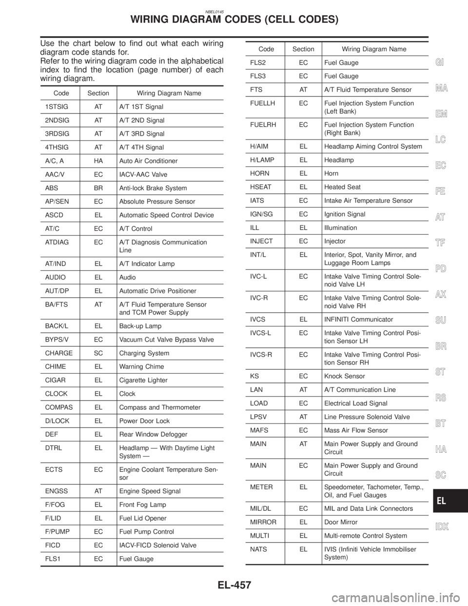
NBEL0145
Use the chart below to find out what each wiring
diagram code stands for.
Refer to the wiring diagram code in the alphabetical
index to find the location (page number) of each
wiring diagram.
Code Section Wiring Diagram Name
1STSIG AT A/T 1ST Signal
2NDSIG AT A/T 2ND Signal
3RDSIG AT A/T 3RD Signal
4THSIG AT A/T 4TH Signal
A/C, A HA Auto Air Conditioner
AAC/V EC IACV-AAC Valve
ABS BR Anti-lock Brake System
AP/SEN EC Absolute Pressure Sensor
ASCD EL Automatic Speed Control Device
AT/C EC A/T Control
ATDIAG EC A/T Diagnosis Communication
Line
AT/IND EL A/T Indicator Lamp
AUDIO EL Audio
AUT/DP EL Automatic Drive Positioner
BA/FTS AT A/T Fluid Temperature Sensor
and TCM Power Supply
BACK/L EL Back-up Lamp
BYPS/V EC Vacuum Cut Valve Bypass Valve
CHARGE SC Charging System
CHIME EL Warning Chime
CIGAR EL Cigarette Lighter
CLOCK EL Clock
COMPAS EL Compass and Thermometer
D/LOCK EL Power Door Lock
DEF EL Rear Window Defogger
DTRL EL Headlamp Ð With Daytime Light
System Ð
ECTS EC Engine Coolant Temperature Sen-
sor
ENGSS AT Engine Speed Signal
F/FOG EL Front Fog Lamp
F/LID EL Fuel Lid Opener
F/PUMP EC Fuel Pump Control
FICD EC IACV-FICD Solenoid Valve
FLS1 EC Fuel Gauge
Code Section Wiring Diagram Name
FLS2 EC Fuel Gauge
FLS3 EC Fuel Gauge
FTS AT A/T Fluid Temperature Sensor
FUELLH EC Fuel Injection System Function
(Left Bank)
FUELRH EC Fuel Injection System Function
(Right Bank)
H/AIM EL Headlamp Aiming Control System
H/LAMP EL Headlamp
HORN EL Horn
HSEAT EL Heated Seat
IATS EC Intake Air Temperature Sensor
IGN/SG EC Ignition Signal
ILL EL Illumination
INJECT EC Injector
INT/L EL Interior, Spot, Vanity Mirror, and
Luggage Room Lamps
IVC-L EC Intake Valve Timing Control Sole-
noid Valve LH
IVC-R EC Intake Valve Timing Control Sole-
noid Valve RH
IVCS EL INFINITI Communicator
IVCS-L EC Intake Valve Timing Control Posi-
tion Sensor LH
IVCS-R EC Intake Valve Timing Control Posi-
tion Sensor RH
KS EC Knock Sensor
LAN AT A/T Communication Line
LOAD EC Electrical Load Signal
LPSV AT Line Pressure Solenoid Valve
MAFS EC Mass Air Flow Sensor
MAIN AT Main Power Supply and Ground
Circuit
MAIN EC Main Power Supply and Ground
Circuit
METER EL Speedometer, Tachometer, Temp.,
Oil, and Fuel Gauges
MIL/DL EC MIL and Data Link Connectors
MIRROR EL Door Mirror
MULTI EL Multi-remote Control System
NATS EL IVIS (Infiniti Vehicle Immobiliser
System)
GI
MA
EM
LC
EC
FE
AT
TF
PD
AX
SU
BR
ST
RS
BT
HA
SC
IDX
WIRING DIAGRAM CODES (CELL CODES)
EL-457
Page 1658 of 2395

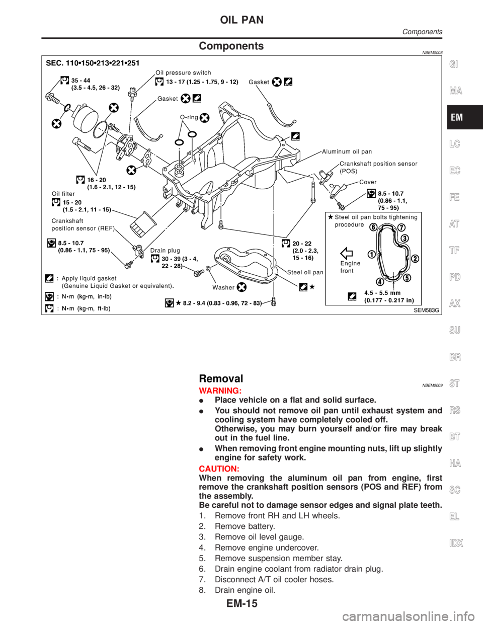
ComponentsNBEM0008
SEM583G
RemovalNBEM0009WARNING:
IPlace vehicle on a flat and solid surface.
IYou should not remove oil pan until exhaust system and
cooling system have completely cooled off.
Otherwise, you may burn yourself and/or fire may break
out in the fuel line.
IWhen removing front engine mounting nuts, lift up slightly
engine for safety work.
CAUTION:
When removing the aluminum oil pan from engine, first
remove the crankshaft position sensors (POS and REF) from
the assembly.
Be careful not to damage sensor edges and signal plate teeth.
1. Remove front RH and LH wheels.
2. Remove battery.
3. Remove oil level gauge.
4. Remove engine undercover.
5. Remove suspension member stay.
6. Drain engine coolant from radiator drain plug.
7. Disconnect A/T oil cooler hoses.
8. Drain engine oil.
GI
MA
LC
EC
FE
AT
TF
PD
AX
SU
BR
ST
RS
BT
HA
SC
EL
IDX
OIL PAN
Components
EM-15